US2299504A - Wrapping machine conveyer and feed mechanism - Google Patents
Wrapping machine conveyer and feed mechanism Download PDFInfo
- Publication number
- US2299504A US2299504A US366984A US36698440A US2299504A US 2299504 A US2299504 A US 2299504A US 366984 A US366984 A US 366984A US 36698440 A US36698440 A US 36698440A US 2299504 A US2299504 A US 2299504A
- Authority
- US
- United States
- Prior art keywords
- belt
- feed
- candies
- plunger
- wrapping
- Prior art date
- Legal status (The legal status is an assumption and is not a legal conclusion. Google has not performed a legal analysis and makes no representation as to the accuracy of the status listed.)
- Expired - Lifetime
Links
- 235000009508 confectionery Nutrition 0.000 description 34
- 238000004513 sizing Methods 0.000 description 8
- 238000012986 modification Methods 0.000 description 2
- 230000004048 modification Effects 0.000 description 2
- 230000000979 retarding effect Effects 0.000 description 2
- 229920000298 Cellophane Polymers 0.000 description 1
- 235000019227 E-number Nutrition 0.000 description 1
- 239000004243 E-number Substances 0.000 description 1
- 206010016173 Fall Diseases 0.000 description 1
- 241001417521 Pomacentridae Species 0.000 description 1
- 235000013736 caramel Nutrition 0.000 description 1
- 238000010276 construction Methods 0.000 description 1
- 239000000463 material Substances 0.000 description 1
- 238000000034 method Methods 0.000 description 1
Images


Classifications
-
- B—PERFORMING OPERATIONS; TRANSPORTING
- B65—CONVEYING; PACKING; STORING; HANDLING THIN OR FILAMENTARY MATERIAL
- B65B—MACHINES, APPARATUS OR DEVICES FOR, OR METHODS OF, PACKAGING ARTICLES OR MATERIALS; UNPACKING
- B65B35/00—Supplying, feeding, arranging or orientating articles to be packaged
- B65B35/30—Arranging and feeding articles in groups
- B65B35/44—Arranging and feeding articles in groups by endless belts or chains
Definitions
- This invention relates to a wrapping machine conveyer and feed mechanism and particularly to one which is employed in a machine particularly adapted for wrapping a number of individually wrapped caramels or other rectangular pieces of candy into a single package.
- the conveyer and feeding mechanism of the jamming caused by variation in the size of the present invention includes a belt feed mechanism This variation in size causes little for bringing the candies to the machine, and a trouble with single candies but when candies are feed plunger mechanism ior removing the proper wrapped together in groups the variation in size number of candies from the feed belt and placof the separate candies add up, and the total ng them in the sizin echanism and subseoi'ten exceeds that which the machine can acquently moving them into the pocket 32 of the One of the principal objects of my wrapping wheel 33.
- the invention is to provide novel feed mechanism for The belt feed mechanism, in general, is similar a machine which eliminates this variation in the to that shown in my U. S. Letters Patent No. 1,654,146, issued December 27, 1927, and need not Another object of my invention is to provide be described in great detail.
- Still another object of my invention is to pro- 5 p eys 38 and 39, in connection with an outboard vide an improved feeding mechanism especially pulley (not shown) serve to carry a feed belt adapted to carry thin candies on edge without The pp each o the feed belt 44 lies in a groove in the top of a fixed plate or feed plunger Still another object of my invention is to probracket 45 and serves to bring candies individualvide a novel method and means for conveying and y pp in er machine to this machine feeding articles to a wrapping machine. to be wrapped up into packages.
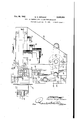
- the cover plate has alarge central aperthe line III-III of Figure 2,100king down in the t re n w h are m nt a l r e number of small rolls 56 which hang down into the path of Figure 4 is a vertical section taken on the line the candies 54.
- Figure 5 is a vertical section taken on the line VV of Figure 1, looking in the direction of the arrows.
- the feed mechanism is intimately related to a sizing mechanism which briefly comprises a sizing plunger 58 mounted in a guide 59 which is intermittently reciprocated in any suitable manner through link 62 and arm-63 (such for example as the manner described in my copending application Serial No. 224,932, new United States Letters Patent No. 2,239,375)
- the feed plunger mechanism is shown in Figures 1, 3 and 4. It comprises a feed plunger l3 having an integral head 14 and reciprocably mounted in a feed plunger slide 15.
- the slide 15 is carried by the feed plunger bracket 45 and is placed at right angles to the path of the belt at and the sizing plunger 58, as shown in Figure l.
- Thehead i i of the feed plunger 13 is considerably wider than the body of the feed plunger and has a backwardly extending skirt or stop it riveted to one side in order to prevent candies from being carried behind it by the belt M when it is in its forward position.
- the feed plunger i3 is provided with a stud l? which projects out laterally through a slot in the feed plunger slide 15 and which is connected by a link 18 to a depending lever 19. These connections are shown in Figure 1.
- the lever 19 is pivoted on a bracket (not shown) fastened to the oil case 22 and is operated by means of a link 8! from a suitable ejector mechanism (not shown).
- the operation of the above described feeding and sizing mechanism is as follows:
- the feed belt M is kept supplied with individually wrapped candies either by an operator who places manually upon it the output of several candywrapping machines or by some suitable mechanism designed for this purpose.
- the feed belt 44 is moved forward a distance equal to or slightly greater than the total thickness of the number of individual candies to be wrapped up in a single package.
- the candies as they are moved up are prevented from falling forward by the rollers 56 which exert a slight retarding force on the upper edges of the candies. This brings the candies up against a candy stop 9
- the desired number of candies is then directly in front of the head M of the feed plunger '13.
- the feed plunger 13 then moves forward in the first step of its forward motion and pushes the desired number of candies off the feed belt 44 and in front of the sizing p1unger53. At this point the feed plunger 13 stops .momentarily.
- the sizing plunger v58 then moves forward from the full line position shown in Figure 3 to the dotted line position shown in the same figure, in which position the distance between its face and the opposed face on thecandy stop 9! is slightly less than the width of the wrapping wheel 33.
- the candies are now squeezed down until they will fit readily into the pockets 32 of the wrapping wheel 33.
- the feed plunger 73 then makes the second step of its forward movement and pushes the candy into a pocket of the wrapping wheel 33, which at this moment is stationary.
- the candies are pushed into the pockets 32 of the wrapping wheel, they carry with them the end 25 of the strip of wrapping material or Cellophane, which has been moved up into position between the feeding and sizing mechanism and the Wrapping wheel.
- a drag means above the belt at said position comprising a plurality of yieldab-ly mounted rollers projecting into the path of said objects.
- a drag means above the belt at said position comprising a plurality of rollers projecting into the path of said objects, horizontal spindles for said rollers, and supporting means having vertically elongated holes receiving said spindles and permitting vertical movement thereof.
- a machine for wrapping a predetermined number of articles into a single package means for receiving a group of said articles, a feed belt passing by said receiving means, a stop member extending across said feed belt in line with one side of said receiving means, a feed plunger, means for moving said feed plunger across said feed belt in front of said stop member and up to said receiving means for pushing groups of said articles thereinto from said belt, the face of said feed plunger being substantially as wide as the length of a row of said predetermined number of articles, and a drag mechanism above the belt'in front of the stop member to keep articles thereon from falling forward, said drag m chanism comprising a plurality of drag members spaced along said belt and individually supported so as to be able to move up under light pressure, each of said drag members being rounded underneath on the side away from the stop member so as to be lifted by oncoming articles.
- a machine for wrapping a predetermined number of articles into a single package means for receiving a group of said articles, a feed belt passing by said receiving means, a stop member extending across said feed belt .in line with one side of said receiving means, a feed plunger, means for moving said plunger across said feed belt in front of said stop member and up to said receiving means for pushing groups of said articles thereinto from said belt, the face of said feed plunger being substantially as wide as the length of a row of said predetermined number of articles, and a drag mechanism above the belt in front of the stop member to keep articles thereon from falling forward, said drag mechanism comprising a plurality of drag members spaced along said belt and individually supported so as to be able to move up under light pressure, each of said drag members being rounded underneath on the side away from the stop member so as to be lifted by oncoming articles and also being rounded underneath on the end towards the feed plunger so as to be lifted by the feed plunger in case it is not already lifted by said articles.
- a feed belt means for moving the feed belt intermittently for carrying objects on edge to a station from which they are pushed off the belt, a drag means above the belt at said station, said drag means comprising a plurality of individually mounted floating members projecting into the path of said objects,
- a drag means above the belt at said position comprising a, plurality of individually mounted floating members which project into the path of said objects and which float on and are supported by said objects as said objects pass therebeneath.
- a feed belt means for moving said feed belt intermittently, a stop extending across the top of said belt, a feed plunger moving across the belt beside the stop and drag means directly above the belt and directly above the path of said plunger for preventing the objects carried on edge by the belt from falling forward, said drag means including a plurality of rollers, said rollers being mounted for limited vertical movement of their axis of rotation and independent of each other, said rollers being positioned to float on said objects when said objects pass therebeneath.
Landscapes
- Engineering & Computer Science (AREA)
- Mechanical Engineering (AREA)
Description
Oct 20, 1942.
w. H. SERGENT} WRAPPING MACHINE CONVEYER AND FEED MECHANISM Original Filed Aug. 15, 1938 3 Sheets-Sheet l Oct. 20, 1942.
W. H. SERGENT WRAPPING MACHINE CONVEYER AND FEED MECHANISM Original Filed Aug. 15, 1938 3 Sheets-Sheet 2 1-2 ya 1 Z :1 44 14 rue 6 4 wvse \Sne azwr.
Oct. 20, 1942. w. H. SERGENT WRAPPING MACHINE CONVEYER AND FEED MECHANISM w Mm NR 1 W 1 W Nu m n MUMIHWJM 5 w J L h UM. mm N vw m Nu r Wm h Z/W/ Ni NYE-Z Z :1
Patented Oct. 20, 1942 WRAPPING MACHINE CONVEYER AND FEED MECHANISM Walter Haynes Sergent, Middletown, N. Y., as-
signor to Ideal Wrapping Machine Company, Middletown, N. Y., a corporation of New York Original application August 15, 1938, Serial No.
224,932. Divided and this application November 25, 1940, Serial No. 366,984
7 Claims.
This invention relates to a wrapping machine conveyer and feed mechanism and particularly to one which is employed in a machine particularly adapted for wrapping a number of individually wrapped caramels or other rectangular pieces of candy into a single package.
candies.
commodate.
size of the candies.
allowing them to fall over.
in the different views:
proper relation and in section.
direction of the arrows.
chine, Serial No. 224.932, filed August 15, 1938,
Machines have been made prior to my invenand assigned to the same assignee as the present tion for wrapping a plurality of candies into a invention. This application has matured into single package, but these machines have required Patent 2,239,375, granted April 22, 1941. frequent attention from the operator because of 10 The conveyer and feeding mechanism of the jamming caused by variation in the size of the present invention includes a belt feed mechanism This variation in size causes little for bringing the candies to the machine, and a trouble with single candies but when candies are feed plunger mechanism ior removing the proper wrapped together in groups the variation in size number of candies from the feed belt and placof the separate candies add up, and the total ng them in the sizin echanism and subseoi'ten exceeds that which the machine can acquently moving them into the pocket 32 of the One of the principal objects of my wrapping wheel 33. invention is to provide novel feed mechanism for The belt feed mechanism, in general, is similar a machine which eliminates this variation in the to that shown in my U. S. Letters Patent No. 1,654,146, issued December 27, 1927, and need not Another object of my invention is to provide be described in great detail. an improved mechanism for feeding candies into a pair of feed belt pu 33 and 9 fixed to a Wrapping mechanism in groups so that several shafts 4! and 32 which are rotatably mounted in candies can be wrapped together. the feed belt bracket (not shown).
Still another object of my invention is to pro- 5 p eys 38 and 39, in connection with an outboard vide an improved feeding mechanism especially pulley (not shown) serve to carry a feed belt adapted to carry thin candies on edge without The pp each o the feed belt 44 lies in a groove in the top of a fixed plate or feed plunger Still another object of my invention is to probracket 45 and serves to bring candies individualvide a novel method and means for conveying and y pp in er machine to this machine feeding articles to a wrapping machine. to be wrapped up into packages.
With these and other objects in view,which will d b p y 33 and 39 are driven through be gme mQIe apparent in the following descriptheir Shafts 4| and 42 in any suitable manner tion and disclosures in the drawings, my inven- Which will cause belt 44 to move forward intertion comprises the novel features of construction mittently 50 that it has p d of rest between and combination hereinafter described and more ch f w d ovement. Thus, the belt 44 comes specifically pointed out in the appended claims, to rest each time that a group of candies is to be In the drawings, which illustrate a preferred removed from it, and then it moves forward again embodiment of this invention and in which simito bring another o p of Candies into p lar reference numerals refer to similar features Since the candies 54 are carried on edge by the belt, as shown in Figure 2, there is. a tendency for Figure 1 is an enlarged plan View of the feedthem, and e pe ithe leading C dy, to fall ing and sizing mechanism of the machine, a po-rforward when the belt starts or stops. tion of the wrapping wheel being shown in its to prevent this, I have provided a drag echanism which exerts a slight retarding force on the Figure 2 is a vertical section through a portion 1 1 edges Of the Candies and p ve ts their of the feeding mechanism taken on the line II- falling fOI'WeTd- This mechanism p es a II of Figure 1 and looking in the direction of the belt COVeI plate 55 Which 1365 directly above the point where the candies 5 5 are removed from the Figure 3 is a horizontal section view taken on belt. The cover plate has alarge central aperthe line III-III of Figure 2,100king down in the t re n w h are m nt a l r e number of small rolls 56 which hang down into the path of Figure 4 is a vertical section taken on the line the candies 54.
IV-IV of Figure 1 and looking in the direction Sp ndles 51 which extend across the openin of the arrows.
Figure 5 is a vertical section taken on the line VV of Figure 1, looking in the direction of the arrows.
This application is a division of my co-pending application for patent entitled Wrapping ma- In brief, it includes These two The inboard In order These rolls are carried on pins in the belt cover plate 55 in a direction transverse to the direction of movement of the belt 44. The ends of the pins 51, as shown in Figure 4, are supported in vertical slots in the belt cover plate 55. This allows the rolls 56 and the pins 51 to rise slightly and allow the candies 54 to pass beneath them, as shown in Figure 2. At the same time, it provides a slight resistance to the forward movement of the upper part of the candies, which I have found desirable in order to prevent their falling forward.
The feed mechanism is intimately related to a sizing mechanism which briefly comprises a sizing plunger 58 mounted in a guide 59 which is intermittently reciprocated in any suitable manner through link 62 and arm-63 (such for example as the manner described in my copending application Serial No. 224,932, new United States Letters Patent No. 2,239,375)
The feed plunger mechanism is shown in Figures 1, 3 and 4. It comprises a feed plunger l3 having an integral head 14 and reciprocably mounted in a feed plunger slide 15. The slide 15 is carried by the feed plunger bracket 45 and is placed at right angles to the path of the belt at and the sizing plunger 58, as shown in Figure l. Thehead i i of the feed plunger 13 is considerably wider than the body of the feed plunger and has a backwardly extending skirt or stop it riveted to one side in order to prevent candies from being carried behind it by the belt M when it is in its forward position.
The feed plunger i3; is provided with a stud l? which projects out laterally through a slot in the feed plunger slide 15 and which is connected by a link 18 to a depending lever 19. These connections are shown in Figure 1. The lever 19 is pivoted on a bracket (not shown) fastened to the oil case 22 and is operated by means of a link 8! from a suitable ejector mechanism (not shown).
The operation of the above described feeding and sizing mechanism is as follows: The feed belt M is kept supplied with individually wrapped candies either by an operator who places manually upon it the output of several candywrapping machines or by some suitable mechanism designed for this purpose. During each cycle of operation of the machine, the feed belt 44 is moved forward a distance equal to or slightly greater than the total thickness of the number of individual candies to be wrapped up in a single package. The candies as they are moved up are prevented from falling forward by the rollers 56 which exert a slight retarding force on the upper edges of the candies. This brings the candies up against a candy stop 9| extending across the feed belt 44 in line with the far side of the wrapping wheel 33. The desired number of candies is then directly in front of the head M of the feed plunger '13. The feed plunger 13 then moves forward in the first step of its forward motion and pushes the desired number of candies off the feed belt 44 and in front of the sizing p1unger53. At this point the feed plunger 13 stops .momentarily. The sizing plunger v58 then moves forward from the full line position shown in Figure 3 to the dotted line position shown in the same figure, in which position the distance between its face and the opposed face on thecandy stop 9! is slightly less than the width of the wrapping wheel 33. If the total width of the candies in this space was originally greater than this dimension, the candies are now squeezed down until they will fit readily into the pockets 32 of the wrapping wheel 33. The feed plunger 73 then makes the second step of its forward movement and pushes the candy into a pocket of the wrapping wheel 33, which at this moment is stationary. As the candies are pushed into the pockets 32 of the wrapping wheel, they carry with them the end 25 of the strip of wrapping material or Cellophane, which has been moved up into position between the feeding and sizing mechanism and the Wrapping wheel.
While I have shown a particular embodiment of my invention, it will, of course, be understood that I do not wish to be limited thereto, since many modifications may be made, and I, therefore, contemplate by the appended claims to cover all such modifications as fall within the true spirit and scope of my invention.
I claim as my invention:
1. In a machine having an intermittently moving belt for carrying objects on edge to a position from which they are pushed laterally off the belt in groups, a drag means above the belt at said position, said drag means comprising a plurality of yieldab-ly mounted rollers projecting into the path of said objects.
2. In a machine having an intermittently moving belt for carrying objects on edge to a position from which they are pushed laterally off the belt in groups, a drag means above the belt at said position, said drag means comprising a plurality of rollers projecting into the path of said objects, horizontal spindles for said rollers, and supporting means having vertically elongated holes receiving said spindles and permitting vertical movement thereof.
3. In a machine for wrapping a predetermined number of articles into a single package, means for receiving a group of said articles, a feed belt passing by said receiving means, a stop member extending across said feed belt in line with one side of said receiving means, a feed plunger, means for moving said feed plunger across said feed belt in front of said stop member and up to said receiving means for pushing groups of said articles thereinto from said belt, the face of said feed plunger being substantially as wide as the length of a row of said predetermined number of articles, and a drag mechanism above the belt'in front of the stop member to keep articles thereon from falling forward, said drag m chanism comprising a plurality of drag members spaced along said belt and individually supported so as to be able to move up under light pressure, each of said drag members being rounded underneath on the side away from the stop member so as to be lifted by oncoming articles.
4. In a machine for wrapping a predetermined number of articles into a single package, means for receiving a group of said articles, a feed belt passing by said receiving means, a stop member extending across said feed belt .in line with one side of said receiving means, a feed plunger, means for moving said plunger across said feed belt in front of said stop member and up to said receiving means for pushing groups of said articles thereinto from said belt, the face of said feed plunger being substantially as wide as the length of a row of said predetermined number of articles, and a drag mechanism above the belt in front of the stop member to keep articles thereon from falling forward, said drag mechanism comprising a plurality of drag members spaced along said belt and individually supported so as to be able to move up under light pressure, each of said drag members being rounded underneath on the side away from the stop member so as to be lifted by oncoming articles and also being rounded underneath on the end towards the feed plunger so as to be lifted by the feed plunger in case it is not already lifted by said articles.
5. In a machine of the class described, a feed belt, means for moving the feed belt intermittently for carrying objects on edge to a station from which they are pushed off the belt, a drag means above the belt at said station, said drag means comprising a plurality of individually mounted floating members projecting into the path of said objects,
6. In a machine having a, feed belt for carrying objects on edge to a position from which they are pushed off the belt, a drag means above the belt at said position, said drag means comprising a, plurality of individually mounted floating members which project into the path of said objects and which float on and are supported by said objects as said objects pass therebeneath.
'7. In a machine of the class described, a feed belt, means for moving said feed belt intermittently, a stop extending across the top of said belt, a feed plunger moving across the belt beside the stop and drag means directly above the belt and directly above the path of said plunger for preventing the objects carried on edge by the belt from falling forward, said drag means including a plurality of rollers, said rollers being mounted for limited vertical movement of their axis of rotation and independent of each other, said rollers being positioned to float on said objects when said objects pass therebeneath.
WALTER HAYNES SERGENT.
Priority Applications (1)
| Application Number | Priority Date | Filing Date | Title |
|---|---|---|---|
| US366984A US2299504A (en) | 1938-08-15 | 1940-11-25 | Wrapping machine conveyer and feed mechanism |
Applications Claiming Priority (2)
| Application Number | Priority Date | Filing Date | Title |
|---|---|---|---|
| US224932A US2239375A (en) | 1938-08-15 | 1938-08-15 | Wrapping machine |
| US366984A US2299504A (en) | 1938-08-15 | 1940-11-25 | Wrapping machine conveyer and feed mechanism |
Publications (1)
| Publication Number | Publication Date |
|---|---|
| US2299504A true US2299504A (en) | 1942-10-20 |
Family
ID=26919141
Family Applications (1)
| Application Number | Title | Priority Date | Filing Date |
|---|---|---|---|
| US366984A Expired - Lifetime US2299504A (en) | 1938-08-15 | 1940-11-25 | Wrapping machine conveyer and feed mechanism |
Country Status (1)
| Country | Link |
|---|---|
| US (1) | US2299504A (en) |
Cited By (7)
| Publication number | Priority date | Publication date | Assignee | Title |
|---|---|---|---|---|
| US2513662A (en) * | 1948-10-05 | 1950-07-04 | Lance Inc | Reciprocating pusher transfer device |
| US2629977A (en) * | 1947-11-04 | 1953-03-03 | Kraft Foods Co | Package top sealing apparatus |
| US2679323A (en) * | 1949-10-25 | 1954-05-25 | Freezing Equipment Sales Inc | Loading and unloading mechanism for quick freeze apparatus |
| US2747349A (en) * | 1950-10-06 | 1956-05-29 | American Mach & Foundry | Wrapping machine |
| US2747352A (en) * | 1952-07-11 | 1956-05-29 | Smith Kline French Lab | Apparatus for packaging wafer tablets |
| US2761359A (en) * | 1950-02-15 | 1956-09-04 | Theodore L Sargent | Automatic feed for box making machines |
| FR2228693A1 (en) * | 1973-05-09 | 1974-12-06 | Seragnoli Ariosto |
-
1940
- 1940-11-25 US US366984A patent/US2299504A/en not_active Expired - Lifetime
Cited By (7)
| Publication number | Priority date | Publication date | Assignee | Title |
|---|---|---|---|---|
| US2629977A (en) * | 1947-11-04 | 1953-03-03 | Kraft Foods Co | Package top sealing apparatus |
| US2513662A (en) * | 1948-10-05 | 1950-07-04 | Lance Inc | Reciprocating pusher transfer device |
| US2679323A (en) * | 1949-10-25 | 1954-05-25 | Freezing Equipment Sales Inc | Loading and unloading mechanism for quick freeze apparatus |
| US2761359A (en) * | 1950-02-15 | 1956-09-04 | Theodore L Sargent | Automatic feed for box making machines |
| US2747349A (en) * | 1950-10-06 | 1956-05-29 | American Mach & Foundry | Wrapping machine |
| US2747352A (en) * | 1952-07-11 | 1956-05-29 | Smith Kline French Lab | Apparatus for packaging wafer tablets |
| FR2228693A1 (en) * | 1973-05-09 | 1974-12-06 | Seragnoli Ariosto |
Similar Documents
| Publication | Publication Date | Title |
|---|---|---|
| US4098392A (en) | Potato chips processing machine | |
| US2324930A (en) | Stacking and boxing apparatus | |
| US2954881A (en) | Separation of articles from a stack | |
| GB1137826A (en) | Improvements in or relating to a method and apparatus for arranging cigarettes in groups of superimposed layers and transferring the groups to a packaging machine | |
| US2776831A (en) | Sheet inverting mechanism | |
| US2686623A (en) | Bottle packing machine | |
| US3112590A (en) | Packaging system and apparatus | |
| US1904613A (en) | Article collecting machine | |
| US2907152A (en) | Method and machine for use in packaging of bacon or the like | |
| US3335841A (en) | Method and apparatus for feeding articles to a packaging machine | |
| US2345310A (en) | Article assembling and feeding machine | |
| US2779592A (en) | Feed hopper | |
| US4083460A (en) | Method and device for forming groups of rodlike articles | |
| US3271023A (en) | Sheet collating apparatus | |
| US4030268A (en) | Packaging machine | |
| US2561070A (en) | Sheet collating mechanism | |
| US1308321A (en) | armstrong | |
| US2952106A (en) | Egg handling plant | |
| US2860554A (en) | Partition assembly machine | |
| US2860762A (en) | Article converger conveyor | |
| US1515589A (en) | Packaging machine | |
| US2817933A (en) | Wrapping machine article conveying mechanism | |
| US3405504A (en) | Transferring system | |
| GB1576718A (en) | Conveyor handling systems | |
| US2241721A (en) | Article handling mechanism for wrapping machines |