US2294271A - Tire removing tool - Google Patents
Tire removing tool Download PDFInfo
- Publication number
- US2294271A US2294271A US411913A US41191341A US2294271A US 2294271 A US2294271 A US 2294271A US 411913 A US411913 A US 411913A US 41191341 A US41191341 A US 41191341A US 2294271 A US2294271 A US 2294271A
- Authority
- US
- United States
- Prior art keywords
- tire
- arm
- tool
- handle bar
- bar
- Prior art date
- Legal status (The legal status is an assumption and is not a legal conclusion. Google has not performed a legal analysis and makes no representation as to the accuracy of the status listed.)
- Expired - Lifetime
Links
Images
Classifications
-
- B—PERFORMING OPERATIONS; TRANSPORTING
- B60—VEHICLES IN GENERAL
- B60C—VEHICLE TYRES; TYRE INFLATION; TYRE CHANGING; CONNECTING VALVES TO INFLATABLE ELASTIC BODIES IN GENERAL; DEVICES OR ARRANGEMENTS RELATED TO TYRES
- B60C25/00—Apparatus or tools adapted for mounting, removing or inspecting tyres
- B60C25/01—Apparatus or tools adapted for mounting, removing or inspecting tyres for removing tyres from or mounting tyres on wheels
- B60C25/02—Tyre levers or the like, e.g. hand-held
Definitions
- the invention aims to provide a simple and inexpensive, yet a convenient and efficient tool for use in removing pneumatic tires from dropcenter rims, the tool being of particular value in connection with tractor tires and other large size tires which often become so rusted upon the rims that it is almost an impossibility to loosen the beads and force them toward the well or drop-center of the rim. With the present tool, however, this may be accomplished with ease and in a very short time.
- Figure 1 is a perspective view of the tool.
- Figure 2 is a side elevation, partly broken away showing the manner of using the tool, the tire, tube and rim being illustrated in dot and dash lines.
- a straight rigid handle bar 5 is provided to extend radially at one side of a tire 6 to be removed from a rim 1.
- This bar 5 is provided with one end surface 8 to receiver hammer blows when driving the tool into operative position, and is provided with another end surface 9 to receive the hammer blows when removing the tool, should it be frictionally held.
- a rigid arm I! which is welded or otherwise rigidly secured to said handle bar, said arm being adapted to extend to the tire side wall adjacent the bead thereof.
- Rigidly joined to the outer end of this arm I is a rigid finger ll extending in a direction substantially parallel with the bar 5, for insertion between the tire bead I2 and the rim flange l3.
- the tool may be removed with ease, and moved circumferentially of the tire to another position, the operation being repeated as many times as necessary to loosen the tire beads and drive them toward the drop-center, permitting them to enter this drop-center or well and thereby allowing removal of the tire.
- the arm l0 and finger II are formed from a single short piece of angle metal, the arm being formed with a semi-circular notch E5 in which the handle bar 5 is welded.
- This brace in the present disclosure, consists of a substantially triangular web It fitting into the angle between the handle bar and arm and welded to both thereof. The outer edge of this web is formed with an inwardly curved portion H to clear the side wall of the tire so that the web will not interfere with delivery of blows direct to the tire bead from the point M.
- the handle bar 5 may here be provided with a raised anvil portion, as shown.
- a tool for loosening pneumatic tires from drop-center rims comprising a straight onepiece rigid handle bar to extend radially at one side of and in outwardly spaced relation with the tire, said handle bar having one end to receive hammer blows to drive the tool endwise to operative position, and another end to receive hammer blows to drive the tool endwise in the other direction to released position, said bar being provided with an integral laterally projecting rigid arm near said other end to extend to the tire side wall and space said handle bar from said wall and the adjacent rim flange, the outer end of said arm being provided with an integral rigid fiat finger disposed in a plane substantially parallel with the length of said bar, said finger projecting away from said one Then, by hammering on end of said bar for insertion between the bead 2 wil 2.
Description
Aug. 25, 1942. c. R. BETHARD TIRE REMOVING TOOL Filed Sept. 22, 1941' Patented Aug. 25, 1942 UNITED STATES PATENT OFFICE TIRE REMOVING TOOL Clarence R. Bethard, Taylorville, Ill.
Application September 22, 1941, Serial No. 411,913
2 Claims.
The invention aims to provide a simple and inexpensive, yet a convenient and efficient tool for use in removing pneumatic tires from dropcenter rims, the tool being of particular value in connection with tractor tires and other large size tires which often become so rusted upon the rims that it is almost an impossibility to loosen the beads and force them toward the well or drop-center of the rim. With the present tool, however, this may be accomplished with ease and in a very short time.
With the above object in view, the invention resides in the subject matter hereinafter described and claimed, description being accomplished by reference to the accompanying drawing.
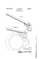
Figure 1 is a perspective view of the tool.
Figure 2 is a side elevation, partly broken away showing the manner of using the tool, the tire, tube and rim being illustrated in dot and dash lines.
A preferred construction has been shown in the drawing and will be specifically described, with the understanding, however, that within the scope of the invention as claimed, minor variations may be made.
A straight rigid handle bar 5 is provided to extend radially at one side of a tire 6 to be removed from a rim 1. This bar 5 is provided with one end surface 8 to receiver hammer blows when driving the tool into operative position, and is provided with another end surface 9 to receive the hammer blows when removing the tool, should it be frictionally held.
Near the end 9 of the handle bar 5 is a rigid arm I!) which is welded or otherwise rigidly secured to said handle bar, said arm being adapted to extend to the tire side wall adjacent the bead thereof. Rigidly joined to the outer end of this arm I is a rigid finger ll extending in a direction substantially parallel with the bar 5, for insertion between the tire bead I2 and the rim flange l3. Thus, hammer blows delivered at the point M on the handle bar 5, opposite the arm ID, will be transmitted by this arm and the finger ll directly to the bead 12, to loosen the latter and drive it toward the well or drop center 1' of the rim. Of course, in order to insert the finger H between the bead and rim flange, it is necessary to drive it into place by delivering hammer blows on the end surface 8 of the handle bar 5, and this initially loosens the bead by a wedging action, more loosening being then accomplished by hammering at the point I4.
the end surface 9, the tool may be removed with ease, and moved circumferentially of the tire to another position, the operation being repeated as many times as necessary to loosen the tire beads and drive them toward the drop-center, permitting them to enter this drop-center or well and thereby allowing removal of the tire.
In the preferred form of construction, the arm l0 and finger II are formed from a single short piece of angle metal, the arm being formed with a semi-circular notch E5 in which the handle bar 5 is welded. When this construction is employed, or any other construction which would require bracing of the arm [0, I provide an appropriate brace extending from the arm to the handle bar. This brace, in the present disclosure, consists of a substantially triangular web It fitting into the angle between the handle bar and arm and welded to both thereof. The outer edge of this web is formed with an inwardly curved portion H to clear the side wall of the tire so that the web will not interfere with delivery of blows direct to the tire bead from the point M.
In order that the hammer blows may be more effectively delivered at the point [4, the handle bar 5 may here be provided with a raised anvil portion, as shown.
From the foregoing and the accompanying drawing, it will be seen that novel and advantageous provision has been made for carrying out the objects of the invention, and while a preferred construction has been illustrated, attention is again invited to the possibility of making variations within the scope of the invention as claimed.
I claim:
1. A tool for loosening pneumatic tires from drop-center rims, comprising a straight onepiece rigid handle bar to extend radially at one side of and in outwardly spaced relation with the tire, said handle bar having one end to receive hammer blows to drive the tool endwise to operative position, and another end to receive hammer blows to drive the tool endwise in the other direction to released position, said bar being provided with an integral laterally projecting rigid arm near said other end to extend to the tire side wall and space said handle bar from said wall and the adjacent rim flange, the outer end of said arm being provided with an integral rigid fiat finger disposed in a plane substantially parallel with the length of said bar, said finger projecting away from said one Then, by hammering on end of said bar for insertion between the bead 2 wil 2. A structure as specified in claim 1; together with a rigid longitudinal brace web at the side of said arm opposite said finger, said brace web being integrally joined to said arm and to said handle bar and having an inwardly curved outer edge to clear the tire side wall.
CLARENCE R. BETHARD.
Priority Applications (1)
| Application Number | Priority Date | Filing Date | Title |
|---|---|---|---|
| US411913A US2294271A (en) | 1941-09-22 | 1941-09-22 | Tire removing tool |
Applications Claiming Priority (1)
| Application Number | Priority Date | Filing Date | Title |
|---|---|---|---|
| US411913A US2294271A (en) | 1941-09-22 | 1941-09-22 | Tire removing tool |
Publications (1)
| Publication Number | Publication Date |
|---|---|
| US2294271A true US2294271A (en) | 1942-08-25 |
Family
ID=23630781
Family Applications (1)
| Application Number | Title | Priority Date | Filing Date |
|---|---|---|---|
| US411913A Expired - Lifetime US2294271A (en) | 1941-09-22 | 1941-09-22 | Tire removing tool |
Country Status (1)
| Country | Link |
|---|---|
| US (1) | US2294271A (en) |
Cited By (10)
| Publication number | Priority date | Publication date | Assignee | Title |
|---|---|---|---|---|
| US2489088A (en) * | 1945-10-13 | 1949-11-22 | Ivan N Hewitt | Lever operated tire loosening device |
| US2582390A (en) * | 1946-07-31 | 1952-01-15 | Earl W Moore And Harry A Warde | Tire removing apparatus of the percussion type |
| US5123470A (en) * | 1990-11-26 | 1992-06-23 | Tran Loi V | Tire removal tool |
| US5265661A (en) * | 1990-11-26 | 1993-11-30 | Tran Loi V | Tire removal tool |
| US6684927B1 (en) | 2000-10-24 | 2004-02-03 | Summit Tool Company | Tire mounting tool |
| US6712114B2 (en) | 2000-10-24 | 2004-03-30 | Summit Tool Company | Tire working tool |
| US20060137829A1 (en) * | 2004-12-23 | 2006-06-29 | Tran Loi V | Tire removal tool |
| US20060196610A1 (en) * | 2005-03-01 | 2006-09-07 | Brahler Richard W Ii | Tire working tool |
| US7156141B1 (en) | 2006-05-16 | 2007-01-02 | Summit Tool Company | Tire demounting tool |
| US7163041B1 (en) | 2005-10-11 | 2007-01-16 | Loi Van Tran | Tire installation and removal tool |
-
1941
- 1941-09-22 US US411913A patent/US2294271A/en not_active Expired - Lifetime
Cited By (14)
| Publication number | Priority date | Publication date | Assignee | Title |
|---|---|---|---|---|
| US2489088A (en) * | 1945-10-13 | 1949-11-22 | Ivan N Hewitt | Lever operated tire loosening device |
| US2582390A (en) * | 1946-07-31 | 1952-01-15 | Earl W Moore And Harry A Warde | Tire removing apparatus of the percussion type |
| US5123470A (en) * | 1990-11-26 | 1992-06-23 | Tran Loi V | Tire removal tool |
| US5265661A (en) * | 1990-11-26 | 1993-11-30 | Tran Loi V | Tire removal tool |
| US20040226660A1 (en) * | 2000-10-24 | 2004-11-18 | Roger Kliskey | Tire working tool |
| US6712114B2 (en) | 2000-10-24 | 2004-03-30 | Summit Tool Company | Tire working tool |
| US6684927B1 (en) | 2000-10-24 | 2004-02-03 | Summit Tool Company | Tire mounting tool |
| US6913061B2 (en) | 2000-10-24 | 2005-07-05 | Summit Tool Company | Tire working tool |
| US20060137829A1 (en) * | 2004-12-23 | 2006-06-29 | Tran Loi V | Tire removal tool |
| US7124800B2 (en) | 2004-12-23 | 2006-10-24 | Loi Van Tran | Tire removal tool |
| US20060196610A1 (en) * | 2005-03-01 | 2006-09-07 | Brahler Richard W Ii | Tire working tool |
| US7267155B2 (en) | 2005-03-01 | 2007-09-11 | Brahler Ii Richard W | Tire working tool |
| US7163041B1 (en) | 2005-10-11 | 2007-01-16 | Loi Van Tran | Tire installation and removal tool |
| US7156141B1 (en) | 2006-05-16 | 2007-01-02 | Summit Tool Company | Tire demounting tool |
Similar Documents
| Publication | Publication Date | Title |
|---|---|---|
| US2294271A (en) | Tire removing tool | |
| US2311789A (en) | Tire iron | |
| US3649976A (en) | Combination tool for use with vehicle wheels | |
| US1567025A (en) | Automobile tire tool | |
| US4744132A (en) | Lock ring assembly and disassembly method | |
| US3029502A (en) | Tool for removing hub caps | |
| US1581119A (en) | Combunation tool | |
| US3280455A (en) | Axle puller with sliding hammer | |
| US2753923A (en) | Fluid pressure actuated tire bead loosening tool | |
| US3779106A (en) | Wheel wrench adapter | |
| US2701707A (en) | Wheel lifting implement | |
| US1344533A (en) | Tool for straightening clencher-rims | |
| US2621715A (en) | Pivotally mounted axially traveling tire removing tool | |
| US2860408A (en) | Muffler tail pipe removing tool | |
| US2684710A (en) | Screw actuated tire bead loosening tool | |
| US2760563A (en) | Tool and method for loosening tire beads | |
| US1100032A (en) | Tire-tool. | |
| US3302275A (en) | Tire tool | |
| US2563987A (en) | Tool for separating the bead of a tire from a rim flange | |
| US2573233A (en) | Lever type tire bead loosening tool | |
| US2851769A (en) | Grease cap assembling tool | |
| US2684113A (en) | Percussion type tire bead loosening tool | |
| US1454320A (en) | Tire tool | |
| US20180022173A1 (en) | Tire Bead Breaking Tool | |
| US2316023A (en) | Tire removing tool |