US2277458A - Differential driving mechanism - Google Patents
Differential driving mechanism Download PDFInfo
- Publication number
- US2277458A US2277458A US276039A US27603939A US2277458A US 2277458 A US2277458 A US 2277458A US 276039 A US276039 A US 276039A US 27603939 A US27603939 A US 27603939A US 2277458 A US2277458 A US 2277458A
- Authority
- US
- United States
- Prior art keywords
- sprocket
- work piece
- chain
- arm
- driving mechanism
- Prior art date
- Legal status (The legal status is an assumption and is not a legal conclusion. Google has not performed a legal analysis and makes no representation as to the accuracy of the status listed.)
- Expired - Lifetime
Links
Images
Classifications
-
- B—PERFORMING OPERATIONS; TRANSPORTING
- B23—MACHINE TOOLS; METAL-WORKING NOT OTHERWISE PROVIDED FOR
- B23Q—DETAILS, COMPONENTS, OR ACCESSORIES FOR MACHINE TOOLS, e.g. ARRANGEMENTS FOR COPYING OR CONTROLLING; MACHINE TOOLS IN GENERAL CHARACTERISED BY THE CONSTRUCTION OF PARTICULAR DETAILS OR COMPONENTS; COMBINATIONS OR ASSOCIATIONS OF METAL-WORKING MACHINES, NOT DIRECTED TO A PARTICULAR RESULT
- B23Q5/00—Driving or feeding mechanisms; Control arrangements therefor
-
- B—PERFORMING OPERATIONS; TRANSPORTING
- B23—MACHINE TOOLS; METAL-WORKING NOT OTHERWISE PROVIDED FOR
- B23Q—DETAILS, COMPONENTS, OR ACCESSORIES FOR MACHINE TOOLS, e.g. ARRANGEMENTS FOR COPYING OR CONTROLLING; MACHINE TOOLS IN GENERAL CHARACTERISED BY THE CONSTRUCTION OF PARTICULAR DETAILS OR COMPONENTS; COMBINATIONS OR ASSOCIATIONS OF METAL-WORKING MACHINES, NOT DIRECTED TO A PARTICULAR RESULT
- B23Q2705/00—Driving working spindles or feeding members carrying tools or work
- B23Q2705/005—General aspects of driving arrangements in a lathe, e.g. indexing the spindle, devices for keeping the cutting speed constant, braking or reversing devices
-
- F—MECHANICAL ENGINEERING; LIGHTING; HEATING; WEAPONS; BLASTING
- F16—ENGINEERING ELEMENTS AND UNITS; GENERAL MEASURES FOR PRODUCING AND MAINTAINING EFFECTIVE FUNCTIONING OF MACHINES OR INSTALLATIONS; THERMAL INSULATION IN GENERAL
- F16H—GEARING
- F16H7/00—Gearings for conveying rotary motion by endless flexible members
- F16H7/08—Means for varying tension of belts, ropes, or chains
- F16H2007/0863—Finally actuated members, e.g. constructional details thereof
- F16H2007/0874—Two or more finally actuated members
Description
- March 24,1942. P. SCHULTZE 9 9 8 DIFFERENTIAL DRIVING MECHANISM Filed May 2'7, 1939 2 Sheets-Sheet 1 v INVENTQR faufi Schultze ATTORNEY March 24, 1942. P. SCHULTZE 2,277,458
PIFFERENTIAL DRIVING MECHANISM Filed May 27, 1959 2 She ets-Sheet 2 I INVENTOR 1 and Schultze 7 BY ma, MW 44 ATTORNEYS Patented Mar. 24, 1942 UNITED STATES PATENT OFFICE DIFFERENTIAL DRIVING MECHANISM Application May 27, 1939, Serial No. 276,039
2 Claims.
This invention relates to a machine element, and more particularly to a differential drive mechanism for a machine tool or the like.
One of the objects of this invention is to provide a differential speed drive which is simple and inexpensive in construction and yet thoroughly durable and reliable in operation. Another object is to provide mechanism of the above nature which is applicable to a variety of machine tools for facilitating the fabrication of work pieces of irregular peripheral contour. Another object is to provide differential speed drive mechanism characterized by driving and driven members connected by a flexible element, together with apparatus which maintains the flexible member in a taut condition. Other objects will be in part apparent and in part pointed out.
The invention accordingly consists in the features of construction, combinations of elements, and arrangements of parts as will be exemplified in the structure to be hereinafter described and the scope of the application of which will be indicated in the following claims.
In the accompanying drawings, in which is shown one of the possible embodiments of my invention.
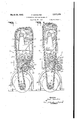
Figure 1 is a front elevation of the differential speed mechanism in one operative position;
Figure 2 is a view similar to Figure 1, but showing the mechanism in another operative position; and,
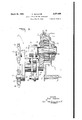
Figure 3 is a fragmentary elevation, partly in section, of the idler apparatus shown in Figures 1 and 2.
Similar reference characters refer to similar parts throughout the various views of the drawmgs,
Various kinds of machine tools and similar apparatus require variable speed mechanism capable of imparting non-uniform rotation to the work piece being operated on. This is particularly true in the case of a work piece the peripheral contour of which is irregular and the work piece is being rotated for machining purposes. By reason of the irregular peripheral contour of the work piece, its circumferential velocity varies directly, as its different radii, although its R. P. M. is constant. This condition results in numerous difliculties, especially so Where the machining operation is a delicate one, or where relatively high speed operation is desirable or where it is important that the peripheral speed of the work piece be maintained at a constant value.
While apparatus is available for imparting uniform circumferential velocity to certain types of non-circular bodies, such apparatus is generally complicated and expensive, and has practical limitations which confine its use to relatively few purposes. This type of apparatus is furthermore of little use where the machining operation is to be carried out on an asymmetrical work piece. Other disadvantages are inherent in such apparatus, and it is to the overcoming of these, in addition to those referred to, that my invention is directed.
Referring now to Figure 1 of the drawings, a machine tool is generally indicated at 10, and includes a head ll mounted on the top of a column I2, the base 13 of which conveniently forms a housing for a motor or other prime mover l4. Motor l4 includes an armature shaft I5, on which is secured in any suitable manner a drive menrber l6, preferably a sprocket. A bracket or spindle support I1 is secured to head II in the machine, and includes at its upper end a journal l8 in which a spindle I9, is rotatably mounted. Spindle [9 has secured thereto a driven member, preferably a sprocket, generally indicated at 20, this sprocket being connected to drive sprocket l6 by a link chain 2|. Under certain circum stances, the driving and driven members It and 20 may be pulleys connected by a flexible belt.
Illustratively, sprocket 20 includes a pair of arcuate toothed portions 22 and 23 disposed substantially at from one another with respect to the axis of rotation of sprocket 20 which is the axis of spindle [9, the sides 24 of the sprocket preferably being plain, i. e. having no teeth formed therein. While toothed portions 22 and 23, as shown, are generated from the same axis, I do not intend to be limited tosuch a formation, as the peripheral contour of sprocket 20 may be any one of a wide variety, depending primarily upon the peripheral contour of the work piece which the machine tool is operating on. Thus, regardless of the contour of sprocket 20, it will be clear that a constant speed rotation of drive sprocket I6 will impart a varying rate of rotation to driven sprocket 20, but at the same time will maintain the circumferential velocity of sprocket 20 at a constant value. From this it follows that if there is mounted on spindle IS a work piece the peripheral contour of which is substantially similar to that of sprocket 20, such Work piece will rotate at a variable rate but at a constant circumferential velocity. Assuming such a work piece is being abraded peripherally, all portions thereof will receive uniform abrasion.
By reason of the irregular peripheral contour of driven sprocket 20, the slack in chain 2| will vary in accordance with the attitude of sprocket 20. As shown in Figure 1, there is a substantial amount of slack in chain 2|, whereas in Figure 2, wherein sprocket portion 23 is at the top of its travel, there is but a slight amount of slack in the chain. To accommodate the slackness in the chain, and to maintain the tension thereof at a substantially constant value, I provide the slack adjuster mechanism which is generally indicated at 25 in Figures 1 and 2.
Referring to Figure 3, column |2 of machine I!) has an opening 26 formed therein'which'receives a mounting 21 adapted to support a pair of ball bearings or other suitable anti-frictionaxis of arm 46. The least slack in chain 2| occurs when sprocket portion 23 (Figure 2) is at its uppermost position, wherein the power exerted by lever arm 34a is the least, by reason of the slight displacement of link 49 from the axis of arm 46.
It may now be seen that arm 34a is in effect a lever of the third order, whereas arm 46, together with arms 39 and 40 comprise a double .10 angular lever of the first order, and by reason of the arrangement of these levers, and the relationship of one to the other, as aiforded by link' 49, the decreasing strength of spring 32 (Figure 3) which biases arm or lever 34a clockwise, is compensated for by the increasing medevices 28 and 29, the innerraces'of which".
carry a stud 3i) suitably slotted as at 3| to receive the inner end 32a of a coil.spring.32..' Th'e outer end (not shown) of spring 32 is suitably,
attached to mounting 21.
chanic'al advantage resulting from the displacement of link 49 from the pivotal axes of arms 39, 40,;and.46.. Thus, the mechanical advantage of lever .46 increases as the power of the spring decreases, with the result that the power out bias of the spring. As shownin Figures 1 and 2, an arm 34a is preferably formedintegrally with and extends from hub 34.-.
Still referring to Figure 3, I provide a stud or post 36 whichextends. from the side of column l2, and which rotatably, or rockably mounts a hub 31 adapted to rotate about the axis of stud 36. Hub 3! is spaced fromcolumn |2 by a suitable spacer 38 to clear hub 34. formed with hub 31 are a pair of arms 39 and 40 extending in opposite directions and carrying respectively pivots 4| and 42, each adapted to receive a ball bearing such asthat shown, at 43 on pivot 4|. These bearings rotatably mount idler sprockets 44 and 45 which are adapted to rotate about the axes of pivots 4| and 42. Hub 3'! also has extending therefrom an arm 46 (Figures 1 and 2). The free ends of arms 34a. and 46 are provided respectively with studs .41 and 48, to which are attached the opposite ends of a link 49, which thus links arms 34a and 46 together.
Spring 32 (Figure 3) mounting 21 as to bias stud 3|), and accordingly arm 34a (Figure l) in a clockwise direction. Thus, under the bias of spring arm 46, arms 39 and 40, and with them idler sprockets 44 and lntegl'ally is so arranged within" put ,of. .lever. .46 ;is. maintained at ;a substantially constantyalue From the, above,. it ,will. appear, that .idler. sprockets 44. and are constantly urged against the opposite sides of .chain 2| .with .a unifo1tm pressure, regardless;.,of;,thaamount. of slack in.
the chain.
As many ,possible. embodiments. may ,be, made of the above invention, and as. many changes goqmight be made in,;the,,embodiment aboveset forth, itisto be understoodthat all matter here: inbefore set forth orshownjn the accompany: ingdrawings is ,to be interpreted as illustrative and not, in a limiting sense.
I claim;
1. In a drive mechanism, for. a machineltool which operates on a work piece of, irregular peripheral contour, the combination withthe driven spindle of such a machinepf a .drivensprocket JULJ'SGCLIIGd to said spindle, a circular, driving sprocket, and a power transmission ,chain, connected to said sprockets...said.-,first-mentioned sprocket having an irregular .peripheralcontour.which corresponds substantially to.the contouruof, the
1work piece wherebyupon operation of .the machine the work piece rotates at a substantially uniform circumferentialv velocity,
2. In, a, drive -mechanism'gfor a. machine. tool which operates on a .work piece 20f: irregular, pe-
50 'ripheral contour,-the combination with.the .driv- 45, tend to rotate about the axis of .hub 31 in a clockwise direction. Hence, sprockets 44 and,
45 which are respectively positioned on the outside and inside of chain 2| bear against. and
en spindle of such a machine of. a driven sprocket secured to said spindle, a circular, driving sprocket, a powertransmission chain C011". nected to said sprockets, said first-mentioned sprocket having an irregular. peripheral-:con-
take up the slack in the chain. Maximum slack tour which corresponds substantially to. the contour of the work piece whereby upon operation of the machine the workzpiecerotates at a sub,- stantially uniform circumferential velocity, and
-means, for maintaining said .chain taut.
- PAUL SCHULTZE.
Priority Applications (1)
| Application Number | Priority Date | Filing Date | Title |
|---|---|---|---|
| US276039A US2277458A (en) | 1939-05-27 | 1939-05-27 | Differential driving mechanism |
Applications Claiming Priority (1)
| Application Number | Priority Date | Filing Date | Title |
|---|---|---|---|
| US276039A US2277458A (en) | 1939-05-27 | 1939-05-27 | Differential driving mechanism |
Publications (1)
| Publication Number | Publication Date |
|---|---|
| US2277458A true US2277458A (en) | 1942-03-24 |
Family
ID=23054894
Family Applications (1)
| Application Number | Title | Priority Date | Filing Date |
|---|---|---|---|
| US276039A Expired - Lifetime US2277458A (en) | 1939-05-27 | 1939-05-27 | Differential driving mechanism |
Country Status (1)
| Country | Link |
|---|---|
| US (1) | US2277458A (en) |
Cited By (13)
| Publication number | Priority date | Publication date | Assignee | Title |
|---|---|---|---|---|
| US2562406A (en) * | 1945-05-09 | 1951-07-31 | Seth S Barker | Enclosed chain conveyer hanger |
| US2683993A (en) * | 1951-05-17 | 1954-07-20 | Diamond Chain Company Inc | Phase shifting device |
| US2789585A (en) * | 1951-04-05 | 1957-04-23 | Super Sagless Spring Company | Cut-off mechanism for zig zag wire |
| US3474895A (en) * | 1968-01-04 | 1969-10-28 | Florian F Dauenhauer | Vine carrier for hop picking machine |
| US4865577A (en) * | 1988-09-08 | 1989-09-12 | Trustees Of Columbia University In The City Of New York | Noncircular drive |
| US20060264285A1 (en) * | 2001-11-27 | 2006-11-23 | Litens Automotive | Synchronous drive apparatus and methods |
| US20070010362A1 (en) * | 2005-07-08 | 2007-01-11 | Schaeffler Kg | Wraparound drive |
| US20070006836A1 (en) * | 2005-07-08 | 2007-01-11 | Schaeffler Kg | Traction mechanism drive having vibration damping |
| US20090239693A1 (en) * | 2005-07-14 | 2009-09-24 | Dayco Europe S.R.L. | Tensioner for a Drive Belt of a Motor Vehicle |
| US20120252622A1 (en) * | 2011-03-31 | 2012-10-04 | Tai-Her Yang | Treadle-drive eccentric wheel transmission wheel series with periodically varied speed ratio |
| US20140171240A1 (en) * | 2012-12-18 | 2014-06-19 | Tai-Her Yang | Noncircular Synchronous Transmission Pulley Set Having Periodically Varying Speed Ratio and Circumference Compensating Function |
| US20140171239A1 (en) * | 2012-12-18 | 2014-06-19 | Tai-Her Yang | Transmission Wheel System Series with Periodically Varied Speed Ratio and Having Reciprocally Displacing Auxiliary Pulley for Storing/Releasing Kinetic Energy |
| US20140171241A1 (en) * | 2012-12-18 | 2014-06-19 | Tai-Her Yang | Transmission wheel series with periodically varied speed ratio and having reciprocally displacing auxiliary pulley for storing/releasing kinetic energy |
-
1939
- 1939-05-27 US US276039A patent/US2277458A/en not_active Expired - Lifetime
Cited By (23)
| Publication number | Priority date | Publication date | Assignee | Title |
|---|---|---|---|---|
| US2562406A (en) * | 1945-05-09 | 1951-07-31 | Seth S Barker | Enclosed chain conveyer hanger |
| US2789585A (en) * | 1951-04-05 | 1957-04-23 | Super Sagless Spring Company | Cut-off mechanism for zig zag wire |
| US2683993A (en) * | 1951-05-17 | 1954-07-20 | Diamond Chain Company Inc | Phase shifting device |
| US3474895A (en) * | 1968-01-04 | 1969-10-28 | Florian F Dauenhauer | Vine carrier for hop picking machine |
| US4865577A (en) * | 1988-09-08 | 1989-09-12 | Trustees Of Columbia University In The City Of New York | Noncircular drive |
| WO1990002894A1 (en) * | 1988-09-08 | 1990-03-22 | Trustees Of Columbia University | Noncircular drive |
| US8303444B2 (en) | 2001-11-27 | 2012-11-06 | Litens Automotive Partnership | Synchronous drive apparatus and methods |
| US20060264285A1 (en) * | 2001-11-27 | 2006-11-23 | Litens Automotive | Synchronous drive apparatus and methods |
| US20080071508A1 (en) * | 2001-11-27 | 2008-03-20 | Litens Automotive | Synchronous drive apparatus and methods |
| US7720650B2 (en) | 2001-11-27 | 2010-05-18 | Litens Automotive | Synchronous drive apparatus and methods |
| US20070010362A1 (en) * | 2005-07-08 | 2007-01-11 | Schaeffler Kg | Wraparound drive |
| US20070006836A1 (en) * | 2005-07-08 | 2007-01-11 | Schaeffler Kg | Traction mechanism drive having vibration damping |
| US20090239693A1 (en) * | 2005-07-14 | 2009-09-24 | Dayco Europe S.R.L. | Tensioner for a Drive Belt of a Motor Vehicle |
| US8439780B2 (en) * | 2005-07-14 | 2013-05-14 | Dayco Europe S.R.L. | Tensioner for a drive belt of a motor vehicle |
| US20120252622A1 (en) * | 2011-03-31 | 2012-10-04 | Tai-Her Yang | Treadle-drive eccentric wheel transmission wheel series with periodically varied speed ratio |
| US9039553B2 (en) * | 2011-03-31 | 2015-05-26 | Tai-Her Yang | Treadle-drive eccentric wheel transmission wheel series with periodically varied speed ratio |
| US20150226293A1 (en) * | 2011-03-31 | 2015-08-13 | Tai-Her Yang | Treadle-drive eccentric wheel transmission wheel series with periodically varied speed ratio |
| US20140171240A1 (en) * | 2012-12-18 | 2014-06-19 | Tai-Her Yang | Noncircular Synchronous Transmission Pulley Set Having Periodically Varying Speed Ratio and Circumference Compensating Function |
| US20140171239A1 (en) * | 2012-12-18 | 2014-06-19 | Tai-Her Yang | Transmission Wheel System Series with Periodically Varied Speed Ratio and Having Reciprocally Displacing Auxiliary Pulley for Storing/Releasing Kinetic Energy |
| US20140171241A1 (en) * | 2012-12-18 | 2014-06-19 | Tai-Her Yang | Transmission wheel series with periodically varied speed ratio and having reciprocally displacing auxiliary pulley for storing/releasing kinetic energy |
| US9169903B2 (en) * | 2012-12-18 | 2015-10-27 | Tai-Her Yang | Transmission wheel system series with periodically varied speed ratio and having reciprocally displacing auxiliary pulley for storing/releasing kinetic energy |
| US9243691B2 (en) * | 2012-12-18 | 2016-01-26 | Tai-Her Yang | Noncircular synchronous transmission pulley set having periodically varying speed ratio and circumference compensating function |
| US9255629B2 (en) * | 2012-12-18 | 2016-02-09 | Tai-Her Yang | Transmission wheel series with periodically varied speed ratio and having reciprocally displacing auxiliary pulley for storing/releasing kinetic energy |
Similar Documents
| Publication | Publication Date | Title |
|---|---|---|
| US2277458A (en) | Differential driving mechanism | |
| JPH07259935A (en) | Belt tensioner | |
| US4625582A (en) | Harmonic drive apparatus | |
| US5759125A (en) | Eccentrically supported tensioner | |
| US3071980A (en) | Drive-tensioning apparatus | |
| US4574531A (en) | Self correcting belt tracking mechanism | |
| US1848423A (en) | Reversible spindle drive for spinning and twisting frames | |
| ATE122439T1 (en) | DEVICE FOR TENSIONING DRIVE BELT. | |
| US2430798A (en) | Motor transmission | |
| US729197A (en) | Motor-cycle gear. | |
| US2737820A (en) | Variable speed friction drive device | |
| CN210440538U (en) | Engine and belt tensioning device therefor | |
| US2636396A (en) | Adapter control assembly for variable-speed power transmission | |
| US3665780A (en) | Tensioning assemblies for drive chains | |
| US4406174A (en) | Noise reducing arrangement for gears | |
| US3446088A (en) | Variable ratio drive | |
| US958274A (en) | Power-transmitting pulley. | |
| US2248256A (en) | Flexible drive | |
| JP3402461B2 (en) | Belt tensioner | |
| US1022756A (en) | Belt-gearing. | |
| US1663596A (en) | Drive mechanism for polishing lathes | |
| JPH08270742A (en) | Belt tensioner | |
| TW202045402A (en) | Motor vehicle with two or more wheels with a device for adjusting the tension of the transmission chain or belt | |
| US905526A (en) | Belt-tightener. | |
| US3037331A (en) | Lens grinding device |