US2267476A - Fluid coupling - Google Patents
Fluid coupling Download PDFInfo
- Publication number
- US2267476A US2267476A US278185A US27818539A US2267476A US 2267476 A US2267476 A US 2267476A US 278185 A US278185 A US 278185A US 27818539 A US27818539 A US 27818539A US 2267476 A US2267476 A US 2267476A
- Authority
- US
- United States
- Prior art keywords
- fluid
- impeller
- passages
- runner
- elements
- Prior art date
- Legal status (The legal status is an assumption and is not a legal conclusion. Google has not performed a legal analysis and makes no representation as to the accuracy of the status listed.)
- Expired - Lifetime
Links
Images

Classifications
-
- F—MECHANICAL ENGINEERING; LIGHTING; HEATING; WEAPONS; BLASTING
- F16—ENGINEERING ELEMENTS AND UNITS; GENERAL MEASURES FOR PRODUCING AND MAINTAINING EFFECTIVE FUNCTIONING OF MACHINES OR INSTALLATIONS; THERMAL INSULATION IN GENERAL
- F16D—COUPLINGS FOR TRANSMITTING ROTATION; CLUTCHES; BRAKES
- F16D33/00—Rotary fluid couplings or clutches of the hydrokinetic type
- F16D33/02—Rotary fluid couplings or clutches of the hydrokinetic type controlled by changing the flow of the liquid in the working circuit, while maintaining a completely filled working circuit
- F16D33/04—Rotary fluid couplings or clutches of the hydrokinetic type controlled by changing the flow of the liquid in the working circuit, while maintaining a completely filled working circuit by altering the position of blades
Definitions
- This invention relates to power trans-mitting devices and refers more particularly to fluid couplings, clutches, drives and the like.
- the principal object of the invention is to eliminate the aforesaid diiculty by providing an improved uid coupling having a fluid control member by means of which the iiuid how between the passages of the impeller and runner members may be automatically and effectively controlled in such manner that, at engine idling speed, there is substantially no circulation of iiuid between the impeller and runner.
- Another object of the invention is to provide a fluid coupling of this character having a fluid control member which is responsive to predetermined speeds of rotation of at least one of the rotating members of the coupling.
- Another object of the invention is to provide a uid coupling having a fluid control member the position of which is controlled by the action of the fluid.
- Another object of the invention is to provide a control mechanism for a fluid coupling of this character which is housed substantially within 4the iiuid passages of the impeller and runner structures in such a manner that the overall length of the fluid coupling need not be increased.
- a further object of the invention is to provide a uid coupling in which the iiow of fluid between the passages of the impeller and runner members is automatically disrupted whenever the speed of the runner exceeds that of the impeller.
- Fig. 1 is a sectional view axially through the improved iiuid coupling.
- Fig. 2 is a vertical sectional view taken on the line 2-2 of Fig. 1.
- Fig. 3 is an enlarged sectional view taken approximately as indicated by the line 3--3 of Fig. l.
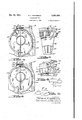
- Fig. 4 is a fragmentary sectional View corresponding to Fig. 1 but illustrating a modified form of the invention.
- Fig. 5 is a fragmentary vertical sectional view taken as indicated bythe line 5 5 of Fig. 4.
- Fig. 6 is a fragmentary sectional view corre sponding to Fig. 1 but illustrating another modified form of the invention.
- Fig. '7 is a fragmentary vertical sectional view taken approximately as indicated by the linev l-'l of Fig. 6.
- FIGs. 8 and 9 vare,diagrammatic views illustrating the action of the fluid under two conditions of operation of the device shown in Fig. 6.
- theimproved fluid coupling is adapted to transmit a drive between a power driving shaft ll such as an engine crankshaft, and a driven shaft il'.
- the driving shaft l I is drivingly connected at i3 to a flywheel It having starter teeth l5 adapted for engagement with the usual engine starting device (not illustrated herein butof well known construction).
- the flywheel Ill has fixed thereto by means of the screws I6 the impeller or driving member ⁇ I1 of the fluid coupling.
- the driven shaft l2 corresponds tothe driving shaft which ordinarily connects the clutch of a vehicle to the transmission mechanism thereof.
- a runner or driven member le of the vfluid coupling it is non-rotatably mounted on the driven shaft l2 by means of the splined connection l2.
- a plurality ci varies it' forming passages or chambers I9 (best shown in Fig. 2) which extend around an annular vortex chamber or space 2li so that as the impeller rotates, the fluid willA be thrown outwardly to a point generally designatedat 2l and toward the passages l@ of the runner lil, thereby inducing rotation of the latter as is generally well known in the art.
- the vanes I9' may be cast integrally with the shell (as illustrated) or the shell and varies may be stamped from sheet material Whereupon the vanes are welded in place.
- a series of annularly arranged recesses 25 and 26 are formed'on the inner face of the impeller and runner structures' respectively and a plu rality of circumferentially spaced gate elements 2l and 28 are pivotally mounted as at 29 Within the recesses 25 and 2B.
- the ends of each of the elements 21 and 28 are interconnected by annu- 2 f l c 2,267,476
- the elements 21 and 28 have tubular portions 34 which extensibly telescope each other and house the springs 30 and 3
- Arcuate slots 25' and 26 are provided ln each' of the vanes I9' of the impeller and runner respectively to accommodate swinging of the gate elements 21, 28. 'I'he elements 21 and 28 are normally yieldingly maintained in ,their illustrated position of Fig. 1
- the elements 21 and 28 are so constructed and arranged with respect to the vanes I8' of the impeller and runner members I1 and I8 respectively that when the impeller rotates at a sulciently high speed the elements 21 and 28 are swung outwardly by the impinging fluid about their plvot 29 and into the recesses 25 and 26.
- the elements 21 and 28 are held in the recesses 25 and 28 by the impinging fluid, the elements are out of fluid interrupting relationship with the passages and do not impede the travel of the fluid.
- a baille or offset portion 32 may be used to assist the function of the baille elements 21 and 28.
- the centrifugal force on the fluid within the coupling becomes greater ,and greater and consequently forces the fluid in its well known travel in the outer portions of the passages I9.
- the impeller I1 will rotate with the driving flywheel I4 to cause the fluid to circulate under the action of centrifugal force from a. space ⁇
- the ow of fluid between the coupling elements is reversed and then flows from the space I8 outwardly through the runner passages for discharge into the space 2
- the fluid then impinges on the outer surface of the gate elements 28 and swings them downwardly about their pivots 29 to thereby' disrupt the fluid flow tending to move from the runner at the space 2
- Such strength that they tend to maintain the gate elements in fluid disrupting position at low motor speeds but permit the fluid to swing the gate elements out of fluid disrupting position at speeds above the motor idling speed. Centrifugal force acting directly upon the gate elements.
- This arrangement of the elements 21 and 28 is particularly effective by reason of their being arranged in the coupling members at a location on the fluid coupling that is at least as far from the axis thereof as the outer diameter of 'the vortex chamber 20, and thereby are adapted to eillciently control the fluid flowy at substantially the maximum outer diameter ofthe passages just before the fluid of the impeller imparts its maximum energy to the runner.
- housed entirely within the fluid passages of the impeller and runner members can be easily balanced and maintained in balance and moved as a unit.
- This feature is of advantage in motor vehicle installations where it may be desirable to remove the coupling when overhauling or repairing the motor or'transmisslon.
- the fluid actuated elements may be used in but one of the impeller and runner structures and the effective lengths of these elements may be varied as desired.
- Figs. 4 and 5 wherein is illustrated a somewhat modified embodiment of the invention, it will be understood that many of the parts correspond to parts previously described' and shown in Figs. 1 to 3 and the entire mechanism will not again be described in detail.
- has formed on its inner face an annular groove 42 within which the spring 40 is suitably fixed in such manner that itis adapted to swing in the arcuately shaped opening 42' provided in the vanes I8 of the impeller.
- the spring 40 comprises a plurality of finger portions 43 which are normally yieldingly urged by the ln- 'herent resiliency of the spring itself into the position illustrated in Fig; 4.
- lare ofv linger portions 43 oppose the passage of fluid simultaneously within all of the passages I9 of the impeller member 4
- the impeller rotates at an increasing speed, the fluid within the impeller impinges on the dat faces of the finger portions 43 and urges the finger portions outwardly into the'groove 42 until, ata critical and predetermined speed, the spring 43 lies flat against the surface of the groove 42.
- the baille ring 50 is provided with a plurality of spaced openings 52 (best shown in Fig. '7) with intermediate wall portions 56 therebetween.
- the openings 52 are adapted to register with the openings of the impeller structure 5
- the bane ring vand its curved side walls in th'e openings 5.2 are so constructed and arranged with respect to the vanes of the impeller and runner members that when the impeller structure 5
- is limited by the extremity 55 of the slot 53 striking'the bolt 54.
- Figs. 8 and 9 illustrate this principle.
- the impeller, designated I is shown leading the rimner, designated R, both elements rotating in the direction of the arrows i and r.
- the baille will be maintained in such position that the wall portions are framed with the vanes i9' of the impeller and will offer no resistance to fluid flow.
- Fig. 9 shows the conditions existing when th'e runner is driving.
- the direction of rotation is of course the same as in Fig. 8, but the flow of fluid has reversed in direction and now exerts force approximately in the direction of the arrow f thereby rotating the baille ring 50 relative'to the impeller to the limit of movement permitted by the screw 54 in the direction indicated by the arrow b.
- the wall portions 55 will th'us oifer resistance to fluid iiow and effect a reduction in torque.
- means for disrupting the flow of uid whenever said driven element runs faster than said driving element comprising an annular. baille plate carried by said driving element and mounted thereon for slight rota- ⁇ tional movement relatively thereto by the force of said fluid, a plurality of passages in said plate adapted to register with the passages of said driving element when said driving element overruns said driven element and which are carried into a. non-registering relationship by movementof said plate when said driven element overruns said driving element.
- a driving element in combination, a driving element, a driven element, a plurality of passages in each of said elements through which pressure fluid is circulated to drive said driven lement, means forscontrolling the flow of pressure uid through said passages comprising an annular pla'te'carried by said driving element, a plurality of passages in said plate which are adapted .to register with the passages of said driving element,.and a lost motion connection between said plate and said driving element wh'ereby the pressure fluid impinging on the sides of the passages of said plate will ⁇ retain t said plate in its registering position relative to the condition when the impeller is driving.
- iiuid torce is then directed approximately in the direction of the arrow l and therefore reacts upon ment.
Landscapes
- Engineering & Computer Science (AREA)
- General Engineering & Computer Science (AREA)
- Mechanical Engineering (AREA)
- Structures Of Non-Positive Displacement Pumps (AREA)
Description
Dec.v23, 1941. 'H' F PATTERSON 2,267,476
` FLUID COUPLING Filed June 9, 1959 2 Sheets-Sheel l A TTU/emi Ys.
Dec, 23, 1941. H. F. PATTERSON I FLUID c'oUPLI'NG 2 Sheets-Sheet 2 Filed June 9. 1939 'l /NVENoR /L/erarzz 7:" YE;
y @IMX/@mz A T T ORNE YS.
Patented Dec. 23, 1941 FLUID COUPLING- Herbert F. Patterson, St. Clair Shores, Mich., as-
signor to Chrysler Corporation, Highland Park, Mich., a corporation of Delaware 3 Claims.
This application is a continuation in part of my copending application, Serial No.y 237,893, filed October 31, 1938, and now abandoned.
y. This invention relates to power trans-mitting devices and refers more particularly to fluid couplings, clutches, drives and the like.
Heretofore in motor vehicle power transmission systems employing duid couplings between the motor and the naldrive mechanism, difficulty has been experienced by reason of the tendency of the vehicle to creep or drive slowly when the engine is idling and the transmission is in gear. In other words, it has been found necessary in bringing the vehicle to rest, to manipulate the transmission into neutral or to apply the usual brakes to oppose the drive or drag transmitted through the fiuid coupling at engine idling speed.
The principal object of the invention is to eliminate the aforesaid diiculty by providing an improved uid coupling having a fluid control member by means of which the iiuid how between the passages of the impeller and runner members may be automatically and effectively controlled in such manner that, at engine idling speed, there is substantially no circulation of iiuid between the impeller and runner.
Another object of the invention is to provide a fluid coupling of this character having a fluid control member which is responsive to predetermined speeds of rotation of at least one of the rotating members of the coupling.
Another object of the inventionis to provide a uid coupling having a fluid control member the position of which is controlled by the action of the fluid.
Another object of the invention is to provide a control mechanism for a fluid coupling of this character which is housed substantially within 4the iiuid passages of the impeller and runner structures in such a manner that the overall length of the fluid coupling need not be increased.
A further object of the invention is to provide a uid coupling in which the iiow of fluid between the passages of the impeller and runner members is automatically disrupted whenever the speed of the runner exceeds that of the impeller.
Further objects and advantages of the invenillustrative embodiments of the principles of the invention, reference being had to the accompany ing drawings, in which: l
Fig. 1 is a sectional view axially through the improved iiuid coupling.
Fig. 2 is a vertical sectional view taken on the line 2-2 of Fig. 1.
Application June 9, 1939, serial No. 278,185
tion will be apparent from the following detailed y Fig. 3 is an enlarged sectional view taken approximately as indicated by the line 3--3 of Fig. l.
Fig. 4 is a fragmentary sectional View corresponding to Fig. 1 but illustrating a modified form of the invention.
Fig. 5 is a fragmentary vertical sectional view taken as indicated bythe line 5 5 of Fig. 4.
Fig. 6 is a fragmentary sectional view corre sponding to Fig. 1 but illustrating another modified form of the invention.
Fig. '7, is a fragmentary vertical sectional view taken approximately as indicated by the linev l-'l of Fig. 6.
Figs. 8 and 9 vare,diagrammatic views illustrating the action of the fluid under two conditions of operation of the device shown in Fig. 6.
In the form of the invention illustrated in the drawings, referring specifically to Fig. 1, theimproved fluid coupling, generally designated by the numeral l0, is adapted to transmit a drive between a power driving shaft ll such as an engine crankshaft, and a driven shaft il'. The driving shaft l I is drivingly connected at i3 to a flywheel It having starter teeth l5 adapted for engagement with the usual engine starting device (not illustrated herein butof well known construction). The flywheel Ill has fixed thereto by means of the screws I6 the impeller or driving member` I1 of the fluid coupling. The driven shaft l2 corresponds tothe driving shaft which ordinarily connects the clutch of a vehicle to the transmission mechanism thereof. A runner or driven member le of the vfluid coupling it is non-rotatably mounted on the driven shaft l2 by means of the splined connection l2.
Formed in the impeller and runnerstructures ll` and i8, respectively, are a plurality ci varies it' forming passages or chambers I9 (best shown in Fig. 2) which extend around an annular vortex chamber or space 2li so that as the impeller rotates, the fluid willA be thrown outwardly to a point generally designatedat 2l and toward the passages l@ of the runner lil, thereby inducing rotation of the latter as is generally well known in the art. The vanes I9' may be cast integrally with the shell (as illustrated) or the shell and varies may be stamped from sheet material Whereupon the vanes are welded in place.
A series of annularly arranged recesses 25 and 26 are formed'on the inner face of the impeller and runner structures' respectively and a plu rality of circumferentially spaced gate elements 2l and 28 are pivotally mounted as at 29 Within the recesses 25 and 2B. The ends of each of the elements 21 and 28 are interconnected by annu- 2 f l c 2,267,476
in which the fluid within each of the passages I9 of the impeller is disrupted principally by the elements 21 when the impeller is rotating at a faster'ratethan the runner structure although at a relatively low speed. If the runner member I8 rotates at a faster speed than the impeller, 15
while both members are rotating at relatively low speed,v the fluid in `each of the passages I9` of the runner is disrupted by reason of the elements 28. The elements 21 and 28 are so constructed and arranged with respect to the vanes I8' of the impeller and runner members I1 and I8 respectively that when the impeller rotates at a sulciently high speed the elements 21 and 28 are swung outwardly by the impinging fluid about their plvot 29 and into the recesses 25 and 26. When the elements 21 and 28 are held in the recesses 25 and 28 by the impinging fluid, the elements are out of fluid interrupting relationship with the passages and do not impede the travel of the fluid.
It is normally desirable to ll the fluid coupling to about three fourths of its capacity,'the fluid being oil, water or other suitable material.
In the operation of this particular embodiment of the invention, when the driving shaft is 33 rotating faster than thedriven shaft I2 but at a relatively low speed, as is the case when the vep to apply the brakes of a'motor vehicle in order to hold the latter at rest. If desired, a baille or offset portion 32 may be used to assist the function of the baille elements 21 and 28. When the vehicle operator increases the speed of the driving shaft to a predetermined speed, the centrifugal force on the fluid within the coupling becomes greater ,and greater and consequently forces the fluid in its well known travel in the outer portions of the passages I9. In other words, the impeller I1 will rotate with the driving flywheel I4 to cause the fluid to circulate under the action of centrifugal force from a. space `|8 outwardly through the impeller passages for discharge into the space A2| where the fluid ene'. ef.
the ow of fluid between the coupling elements is reversed and then flows from the space I8 outwardly through the runner passages for discharge into the space 2| where the fluid enters the impeller passages for discharge at the space 33. The fluid then impinges on the outer surface of the gate elements 28 and swings them downwardly about their pivots 29 to thereby' disrupt the fluid flow tending to move from the runner at the space 2|. such strength that they tend to maintain the gate elements in fluid disrupting position at low motor speeds but permit the fluid to swing the gate elements out of fluid disrupting position at speeds above the motor idling speed. Centrifugal force acting directly upon the gate elements.
will, of course, have a tendency to maintain said elements out of fluid disrupting position at high rotational speeds regardless of the direction of fluid flow. 'Ihe force ofthe fluid impinging upon the outer surface of the elements 28 during coasting, however, is sufllcient under some conditions to overcome this tendency and will swing the elements 28 into the position shown in Fig. 1 if the rotational speed is low enough to permit the force of the fluid plus the force of the spring 30 to overcome the centrifugal eiect.
This arrangement of the elements 21 and 28 is particularly effective by reason of their being arranged in the coupling members at a location on the fluid coupling that is at least as far from the axis thereof as the outer diameter of 'the vortex chamber 20, and thereby are adapted to eillciently control the fluid flowy at substantially the maximum outer diameter ofthe passages just before the fluid of the impeller imparts its maximum energy to the runner.
It ls evident that the improved fluid coupling with its self-contained elements 21 and 28 and springs 38 and 3| housed entirely within the fluid passages of the impeller and runner members can be easily balanced and maintained in balance and moved as a unit. This feature is of advantage in motor vehicle installations where it may be desirable to remove the coupling when overhauling or repairing the motor or'transmisslon. It is to be understood that the fluid actuated elements may be used in but one of the impeller and runner structures and the effective lengths of these elements may be varied as desired.
Referring now to Figs. 4 and 5 wherein is illustrated a somewhat modified embodiment of the invention, it will be understood that many of the parts correspond to parts previously described' and shown in Figs. 1 to 3 and the entire mechanism will not again be described in detail.
It will be noted that the elements 21 and 28 and the springs 38 and 3| of the Fig. l embodiment have been omitted, and an annularly arranged continuous flattened spring 48 has been substituted therefor. Itis to be understood that aithough but one spring 40 is shown in the Fig. 4 embodiment, another may be employed within ther runner member I8 without departing from the bounds of the invention.
To receive the fluid control mechanism, the impeller member 4| has formed on its inner face an annular groove 42 within which the spring 40 is suitably fixed in such manner that itis adapted to swing in the arcuately shaped opening 42' provided in the vanes I8 of the impeller. The spring 40 comprises a plurality of finger portions 43 which are normally yieldingly urged by the ln- 'herent resiliency of the spring itself into the position illustrated in Fig; 4. The flat faces of the The coil springs 30, 3| lare ofv linger portions 43 oppose the passage of fluid simultaneously within all of the passages I9 of the impeller member 4|. yAs the impeller rotates at an increasing speed, the fluid within the impeller impinges on the dat faces of the finger portions 43 and urges the finger portions outwardly into the'groove 42 until, ata critical and predetermined speed, the spring 43 lies flat against the surface of the groove 42.
Upon reversal of uid flow when the vehicle is travelling at low speed, as occurs when the runner drives the impeller, the action of the spring 40 is similar to that just described in connectionwith the gate elements 28 of Fig. 1.
Referring now to Figs. 6 and 'Iv wherein is shown another modification of the invention, it
. will be noted that the elements 21 and28 of the Fig. 1 embodiment and the spring portions 43 of the Fig. 4 embodiment have been omitted, and th'at an adjustable annular baille member 50 is carried by the impeller member 5|. This baflle member is interposed at 2| between the open registering passages of the impeller and runner members and controls the iiuid flow within the passages at the maximum outer diameter of said passages.
, The baille ring 50 is provided with a plurality of spaced openings 52 (best shown in Fig. '7) with intermediate wall portions 56 therebetween. The openings 52 are adapted to register with the openings of the impeller structure 5| and each of the openings 52 has side walls which are inconformity with the wall curvature of the impeller m the impener asl shown in Fig. 6. The bane ring vand its curved side walls in th'e openings 5.2 are so constructed and arranged with respect to the vanes of the impeller and runner members that when the impeller structure 5| rotates faster than the runner structure i8, the fluid from the impeller 5| will react on the curved walls of the ring openings 52 and rotate the ring sufficiently to align the openings 52 with the impeller carried passages I8. This rotative movement of. the baille ring 50 relative to the impeller member 5| is limited by the extremity 55 of the slot 53 striking'the bolt 54. When the runner member rotates at a faster speed than the impeller, the duid within the runner is thrown toward the space 2| as an impelling agent and impinges on the side walls of the ring openings 52 whereby the ring is rotated to bring it into its illustrated position of Fig. 7 wherein the intermediate portions 55 of the baie ring 50 obstruct the flow of fluid into the passages of the impeller. When the baille ring 50 has been moved by the fluid to its 4position of Fig. 7, the portions oi the baille ring between the openings 52 interrupt the uid flow between the runner and impeller members whereby a sufficient reduction in torque is effected, for example, to facilitate changing of speeds in a vehicle transmission.
Figs. 8 and 9 illustrate this principle. In Fig. 8, the impeller, designated I, is shown leading the rimner, designated R, both elements rotating in the direction of the arrows i and r. This is the baille member 50 and tends to move said vmember in the direction of the arrow b. As the rotation of the baffle 50 is limited by the bolt 54, the baille will be maintained in such position that the wall portions are framed with the vanes i9' of the impeller and will offer no resistance to fluid flow.
Fig. 9 shows the conditions existing when th'e runner is driving. The direction of rotation is of course the same as in Fig. 8, but the flow of fluid has reversed in direction and now exerts force approximately in the direction of the arrow f thereby rotating the baille ring 50 relative'to the impeller to the limit of movement permitted by the screw 54 in the direction indicated by the arrow b. The wall portions 55 will th'us oifer resistance to fluid iiow and effect a reduction in torque.
Although but several specific embodiments of the invention are herein shown and described, it will be understood that various changes in the size, shape and arrangement of parts may be made without departing from the spirit of the invention. y
What I claim is:
1. In a fluid coupling of the type wherein a driven element is actuated by a driving element by means of circulation of pressure fluid through passages in said elements, means for disrupting the flow of uid whenever said driven element runs faster than said driving element comprising an annular. baille plate carried by said driving element and mounted thereon for slight rota-` tional movement relatively thereto by the force of said fluid, a plurality of passages in said plate adapted to register with the passages of said driving element when said driving element overruns said driven element and which are carried into a. non-registering relationship by movementof said plate when said driven element overruns said driving element.
2. In a uid coupling of the type wherein a driven element is actuated by a driving element` ment for allowing said plate to be moved circumferentially by the pressure uid.
3. In a uid coupling in combination, a driving element, a driven element, a plurality of passages in each of said elements through which pressure fluid is circulated to drive said driven lement, means forscontrolling the flow of pressure uid through said passages comprising an annular pla'te'carried by said driving element, a plurality of passages in said plate which are adapted .to register with the passages of said driving element,.and a lost motion connection between said plate and said driving element wh'ereby the pressure fluid impinging on the sides of the passages of said plate will` retain t said plate in its registering position relative to the condition when the impeller is driving. The
iiuid torce is then directed approximately in the direction of the arrow l and therefore reacts upon ment.
HERBERT F. PATTERSON.
Priority Applications (2)
| Application Number | Priority Date | Filing Date | Title |
|---|---|---|---|
| US278185A US2267476A (en) | 1939-06-09 | 1939-06-09 | Fluid coupling |
| US410229A US2347121A (en) | 1939-06-09 | 1941-09-10 | Fluid coupling |
Applications Claiming Priority (1)
| Application Number | Priority Date | Filing Date | Title |
|---|---|---|---|
| US278185A US2267476A (en) | 1939-06-09 | 1939-06-09 | Fluid coupling |
Publications (1)
| Publication Number | Publication Date |
|---|---|
| US2267476A true US2267476A (en) | 1941-12-23 |
Family
ID=23064020
Family Applications (1)
| Application Number | Title | Priority Date | Filing Date |
|---|---|---|---|
| US278185A Expired - Lifetime US2267476A (en) | 1939-06-09 | 1939-06-09 | Fluid coupling |
Country Status (1)
| Country | Link |
|---|---|
| US (1) | US2267476A (en) |
Cited By (5)
| Publication number | Priority date | Publication date | Assignee | Title |
|---|---|---|---|---|
| US2529929A (en) * | 1946-11-23 | 1950-11-14 | Twin Disc Clutch Co | Blade blocks in hydraulic couplings |
| US2536842A (en) * | 1946-01-24 | 1951-01-02 | William A Duffield | Rotary turbine type fluid coupling |
| US2674905A (en) * | 1948-04-01 | 1954-04-13 | Packard Motor Car Co | Power transmission mechanism |
| US2862362A (en) * | 1955-05-26 | 1958-12-02 | Gen Motors Corp | Fluid coupling construction |
| US3955367A (en) * | 1973-12-28 | 1976-05-11 | Cluaran Associates Ltd. | Fluid clutches |
-
1939
- 1939-06-09 US US278185A patent/US2267476A/en not_active Expired - Lifetime
Cited By (5)
| Publication number | Priority date | Publication date | Assignee | Title |
|---|---|---|---|---|
| US2536842A (en) * | 1946-01-24 | 1951-01-02 | William A Duffield | Rotary turbine type fluid coupling |
| US2529929A (en) * | 1946-11-23 | 1950-11-14 | Twin Disc Clutch Co | Blade blocks in hydraulic couplings |
| US2674905A (en) * | 1948-04-01 | 1954-04-13 | Packard Motor Car Co | Power transmission mechanism |
| US2862362A (en) * | 1955-05-26 | 1958-12-02 | Gen Motors Corp | Fluid coupling construction |
| US3955367A (en) * | 1973-12-28 | 1976-05-11 | Cluaran Associates Ltd. | Fluid clutches |
Similar Documents
| Publication | Publication Date | Title |
|---|---|---|
| US2710504A (en) | Toroidal chamber type hydraulic torque converter | |
| US2271919A (en) | Turbine torque converter | |
| US2358473A (en) | Fluid coupling | |
| US4167993A (en) | Clutch with inertia control valve | |
| US2267476A (en) | Fluid coupling | |
| US2318187A (en) | Automatic control for fluid transmissions | |
| US3404832A (en) | Fluid coupling | |
| US2162803A (en) | Fluid clutch and turbo-torque converter | |
| US3966031A (en) | Torque converter and slipping clutch | |
| US2440825A (en) | Rotary hydraulic torque converter | |
| US2347121A (en) | Fluid coupling | |
| US2368865A (en) | Combined fluid drive and automatic selective speed power transmission mechanism | |
| US2107089A (en) | Transmission mechanism | |
| US2651918A (en) | Rotary hydraulic torque converter with dynamic braking | |
| US2079691A (en) | Transmission | |
| US2487250A (en) | Rotary fluid coupling and baffle means therefor | |
| US1822555A (en) | Transmission | |
| US3666065A (en) | Speed responsive transmission | |
| US2534517A (en) | Overrunning rotary fluid coupling device | |
| US2700538A (en) | Centrifugal governor | |
| US2168350A (en) | Torque converting and transmitting mechanism | |
| US5263319A (en) | Efficient variable pitch stator with passive control | |
| US2200596A (en) | Hydraulic clutch | |
| US2616537A (en) | Fluid transmission | |
| US3519112A (en) | Fluid coupling with centrifugal roller lock-up clutch |