US2266965A - Refrigerating apparatus - Google Patents
Refrigerating apparatus Download PDFInfo
- Publication number
- US2266965A US2266965A US258597A US25859739A US2266965A US 2266965 A US2266965 A US 2266965A US 258597 A US258597 A US 258597A US 25859739 A US25859739 A US 25859739A US 2266965 A US2266965 A US 2266965A
- Authority
- US
- United States
- Prior art keywords
- compartment
- temperature
- conduit
- liquid
- compartments
- Prior art date
- Legal status (The legal status is an assumption and is not a legal conclusion. Google has not performed a legal analysis and makes no representation as to the accuracy of the status listed.)
- Expired - Lifetime
Links
- 239000007788 liquid Substances 0.000 description 86
- CURLTUGMZLYLDI-UHFFFAOYSA-N Carbon dioxide Chemical compound O=C=O CURLTUGMZLYLDI-UHFFFAOYSA-N 0.000 description 32
- 238000001816 cooling Methods 0.000 description 29
- 239000007787 solid Substances 0.000 description 19
- 229910002092 carbon dioxide Inorganic materials 0.000 description 17
- 229910052751 metal Inorganic materials 0.000 description 10
- 239000002184 metal Substances 0.000 description 10
- 239000003507 refrigerant Substances 0.000 description 9
- 229960004424 carbon dioxide Drugs 0.000 description 8
- 239000001569 carbon dioxide Substances 0.000 description 8
- 238000006073 displacement reaction Methods 0.000 description 8
- 239000012530 fluid Substances 0.000 description 8
- 230000000694 effects Effects 0.000 description 4
- 230000005484 gravity Effects 0.000 description 4
- RYGMFSIKBFXOCR-UHFFFAOYSA-N Copper Chemical compound [Cu] RYGMFSIKBFXOCR-UHFFFAOYSA-N 0.000 description 3
- 230000004888 barrier function Effects 0.000 description 3
- 238000010276 construction Methods 0.000 description 3
- 229910052802 copper Inorganic materials 0.000 description 3
- 239000010949 copper Substances 0.000 description 3
- 238000001704 evaporation Methods 0.000 description 3
- 239000000284 extract Substances 0.000 description 3
- 235000015243 ice cream Nutrition 0.000 description 3
- 238000012986 modification Methods 0.000 description 3
- 230000004048 modification Effects 0.000 description 3
- 238000005192 partition Methods 0.000 description 3
- CSCPPACGZOOCGX-UHFFFAOYSA-N Acetone Chemical compound CC(C)=O CSCPPACGZOOCGX-UHFFFAOYSA-N 0.000 description 2
- 239000002826 coolant Substances 0.000 description 2
- 230000003247 decreasing effect Effects 0.000 description 2
- 235000013305 food Nutrition 0.000 description 2
- 239000011810 insulating material Substances 0.000 description 2
- 239000000463 material Substances 0.000 description 2
- 238000000034 method Methods 0.000 description 2
- 238000013517 stratification Methods 0.000 description 2
- 239000000126 substance Substances 0.000 description 2
- 229910052782 aluminium Inorganic materials 0.000 description 1
- XAGFODPZIPBFFR-UHFFFAOYSA-N aluminium Chemical compound [Al] XAGFODPZIPBFFR-UHFFFAOYSA-N 0.000 description 1
- 239000004020 conductor Substances 0.000 description 1
- 230000008602 contraction Effects 0.000 description 1
- 230000001419 dependent effect Effects 0.000 description 1
- 230000008020 evaporation Effects 0.000 description 1
- 230000005855 radiation Effects 0.000 description 1
- 238000009877 rendering Methods 0.000 description 1
- 238000005476 soldering Methods 0.000 description 1
- 125000006850 spacer group Chemical group 0.000 description 1
- 238000010792 warming Methods 0.000 description 1
Images


Classifications
-
- F—MECHANICAL ENGINEERING; LIGHTING; HEATING; WEAPONS; BLASTING
- F25—REFRIGERATION OR COOLING; COMBINED HEATING AND REFRIGERATION SYSTEMS; HEAT PUMP SYSTEMS; MANUFACTURE OR STORAGE OF ICE; LIQUEFACTION SOLIDIFICATION OF GASES
- F25D—REFRIGERATORS; COLD ROOMS; ICE-BOXES; COOLING OR FREEZING APPARATUS NOT OTHERWISE PROVIDED FOR
- F25D3/00—Devices using other cold materials; Devices using cold-storage bodies
- F25D3/12—Devices using other cold materials; Devices using cold-storage bodies using solidified gases, e.g. carbon-dioxide snow
Definitions
- My invention relates generally to refrigerating apparatus and more particularly to those employing solid carbon dioxide as the cooling agent.
- An object of my invention is to provide a refrigerating system which is relatively uninfluenced by the quantity of solid carbon dioxide in the refrigerating system.
- Another object of my invention is to provide an improved method of transferring heat from one compartment of a refrigerating apparatus to another compartment so .that stratification of temperatures therein is prevented.
- Another object of my invention is to provide an improved cold control means whereby the heat abstracting effect of the solid carbon dioxide is controlled to prevent an undesirable low temperature in the refrigerated compartments.
- Fig. '7 is a view showing a modification of my invention.
- the numeral I designates a rectangular metallic cabinet having end walls 2, 3, side walls 4, 5, a bottom wall 6 and a top wall I.
- a plu-.: rality of rectangular, metallic tubular members. 8 are located within and spaced from the walls
- the tubular members 8 prefof the cabinet I. I erably have their bottom ends closed and their top ends open and terminating below the top wall I of the cabinet 1.
- Each of a plurality of tubular throat members 9 has one end respectively secured in a suitable manner to the top end portions of the tubular members 8 and the top or other end portions extending through apertures in the top wall I of the cabinet'l so fully described hereinafter and the novelty of l the conduit system intact;
- Fig. 3 is a view looking from the right end of the refrigerating apparatus with parts broken away to show the construction of the carbon dioxide compartment and one of the storage compartments;
- Fig. 4 is a view of the weir member and accompanying cold controlling means
- Fig. 5 is a view of the weir member taken along the line 5-5 of Fig. 4 and looking in the direction of the arrows; v
- Fig. 6 is a view of the cold controlling means taken along the line 5-6 of Fig. 4 looking in the direction of the arrows, and
- the throat members 9 are preferably made of a suitable non-heat conducting material, such as rubber, so that heat transfer from the top wall I to the members 8 is held to a minimum.
- the tubular members 8 cooperate respectively with the throat members 9 to form;
- a plurality of compartments I2, l3, l4 and IS may be closed by suitable cover or lid members (not shown) toprevent external air from circulating into the compartments l2, l3, I4 and I5 and thereby further introducing heat to the compartments.
- the compartments l2 and I3 are located ad-. jacent to but spaced from the end walls 2 and3v respectively, and the compartments l4 and i5 are secured together and located intermediate but spaced from the compartments l2 and I3.
- the adjacent top portions of the compartments l2 and i5, and I3 and I5, are secured together by means of U-shaped, metallic members I6, ll respectively.
- the metallic members l6, H are preferably made of'a metal having a high rate of heat conduction, such as copper or aluminunnso that heat may be conducted therethroughfrom; the compartments. i2, #3 to compartmenti 115,
- the adjacent walls of the compartments 14 l ⁇ are separated by a piece of insulating material;
- the compartment I is the refrigerating compartment and is designed -for receiving suitable solid refrigerant medium such as solid CO2, while the compartments
- the compartments l2, l3 are also connected in heat exchange relation with compartment l5 by means of a refrigerant medium circulatory sys-
- may comprise two interconnected conduits 22, 23 having upwardly extending end portions 22 23 respectively, secured to and communicatively connected to a hollow chambered member 24, to be described more completely hereinafter.
- the conduits 22, 23 preferably encircle the tubular members 8 of the compartments l2 and I3 respectively.
- the conduits 22, 23 have downwardly sloping portions 25, 26 respectively, adjacent the tubular member of the compartment l5, and upwardly sloping portions 21, 28 encircling the compartments
- the portions 21, 28 terminate in end portions 215, 28 respectively, secured to and communicatively connected with the member 24 to provide for gravity circulation of a liquid heat transfer medium.
- a sheet metal member 29 Secured to the top portion of the member 8 of compartment l2 and intermediate the compartment l2 and the end wall 2 is a sheet metal member 29 which is preferably of copper or aluminurn.
- the sheet metal member 29 extends downward along the side of and is secured to the tubular member 8 of compartment l2, and at its lower end portion turns outward and upward to receive, in good heat exchange relation, a conduit portion 29 of the upwardly inclined portion 21 of the conduit 22;
- a sheet metal member 30 similar to the member 29 is secured to the upper end portion of the tubular member 8 'of'compartment
- ! and 21 28 respectively, are preferably secured in heat exchange relation to the adjacent portions of the tubular members 8 for additional cooling of the compartments
- which is preferably of copper or aluminum.
- is U-shaped and has a pair of parallel, upstanding leg portions '32, 33, one leg portion being on either side of the tubular member 8 of compartment I5.
- the upstanding portion 32 is intermediate the compartment I5 and the compartment l2, and the upstanding portion 33 is intermediate the compartment l5 and the compartment l3.
- the upstanding portions 32, 33 are each adjacent to but spaced from the vertical side walls of compartment
- the upper end portions of the upstanding portions 32, 33 preferably turn outward and downward and receive, in heat exchange relation, conduit portions 32*, 33 of the portions 25, 26 respectively.
- contains a liquid medium which preferably has a large coeflicient of expansion, such as acetone or methynol, so that the volume thereof will change materially with change in temperature.
- the refrigerant medium which in this case is preferably solid CO2
- in the compartment I5 extracts the-heat from the sheet'metal piece 3
- the liquid medium Upon increase in density of the liquid medium portion, the liquid medium will flow downward within the conduit portion toward the portion 21, and as further liquid medium is cooled within the portion 32, the liquid within the conduit 22 will gradually circulate from the portion 32 downward and upward through the portion 21 to the member 24, from whence itflows downward again to the conduit portion 25.
- the cool liquid medium flows through the conduit portion 29 it abstracts heat from the sheet metal member 29 which thereby increases the temperature of the liquid medium and lessens its density to aid in the natural circulation of the liquid medium through conduit 22.
- the sheet metal member 29 is thereby cooled by the circulating liquid medium so that it in turn cools the upper portion of the tubular member 8 of compartment l2 thereby refrigerating the compartment l2.
- the liquid medium is circulated through the conduit 23 removing heat from the compartment l3 and transferring it to the upstanding portion 33 to be finally transferred to the evaporating CO: within the compartment I5.
- is controlled by means of a temperature control apparatus, generally desig;
- the hollow chambered member 24 comprises a portion.
- the member 24 is the highest point of the circulatory system 2
- the upwardly extending end portions 21, 28 are received in downwardly projecting, oppositely disposed, tubular passageways 53, 54 respectively, and which passageway s '53, 54 are respectively parallel to passageways 5
- , 52 and 53, 54 form respectively the outlet and inlet chambers 55, 56 of the hollow member 24 and are preferably cast integral therewith.
- the outlet chamber 55 is separated from the inlet chamber'55 by a dam or weir member member-,5! actsupon a predetermined lpw-temperature of the liquid medium in the circulatory system 2
- dam 51 is controlled by .means of an adjustment means 58.
- the means 58 comprises a hollow will be at all times maintained the same.
- tubular member 59 of circular cross-section having end walls 68, v6
- a hexagonal, nut-likemem-ber 62 Secured in fixed position within the tubular member 59 is a hexagonal, nut-likemem-ber 62 which has a threaded central aperture 83 therethrough.
- the nut-like member 62 separates the tubular member 58 into upper and lower intercommunicating chambers 64, 65.
- a liquid displacing member 56 Located within and having a slightly smaller cross-section than the lower chamber 55 is a liquid displacing member 56 having a central aperture 81 therethrough.
- a hollow, tubular, cylindrical, externally threaded member 68 extends upward through and in screw-threaded relation with the aperture 83 so that its upper end 69 is located within the chamber 84 and its lower end is within chamber 65.
- a friction member I which may. be a flat, spring like member has its end portions I
- the member I8 is securedin a suitable manner, as by screws I2, to the lower end wall I3 of the fluid displacement member 66 and has an aperture therethrough which registers with the central aperture 61' of the fluid displacement member 66.
- extends downward through the central aperture 61 of the displacement member 86 and through the aperture in the friction member I8 and is suitably secured to the friction member I0, as by peening I3 so that rotation of the member 68 will cause rotation of the friction member I0 and the liquid displacement member 86, and will cause the members 66 and I0 to move vertically within the chamber 65.
- the end portion 68 of the member 68 has a slot I4 in which a suitable tool, such as a screw driver, may be inserted and used for rotating the tubular member 68 in the nut- -like member 62 to position the liquid displacing member 86.
- act to prevent unwanted rotation of the member 66 so that the setting thereof is maintained.
- a conduit I5 has one end I5 secured in fluid tight relation within a central aperture in the end wall 68, and the other end II secured in fluid-tight relation to the lower wall of member 24 and communicating with the outlet chamber 55 so that the liquid medium within the member equalize pressures within the member 24 and the tubular member 59 so that no liquid is caused to flow from or to the chamber 65 due to a difference of pressure between the adjustment member 58 and the system 2
- the member 59 is vertically secured to the side wall 5 of the cabinet I by means of a clamping strip 83 and rivets 84 so that it is in heat exchange relation therewith.
- the member 59 is also secured with respect to the member 24 so that the liquid displacement member 68 may be moved by means of the tubular member 68 through the horizontal plane which passes through the top tilled with a suitabl insulating material so that the rate of heat transfer from the cabinet to the compartments will thereby be lowered to a minimum.
- the compartments l2, l3 are particularly designed as a storage place for bulk ice cream, or the like.
- Compartment I4 is primarily designed for the storage of package goods, such as pre-packed ice cream.
- the compartment M will therefore preferably be run at a lower temperature than the compartments I2, l3 and its temperature is not adjustable by the temperature adjustment means 58.
- the compartment II is refrigerated by and is in good heat exchange relation with the refrigerated compartment l5 solely at the top portion thereof, through the rivets l8 and the rectangular metallic member. 28, but theinsulating material
- is preferably closed by means of an externally threaded, bolt-like member 88 which is easily removable for adjustment. ,As is shown in Fig.
- the adjust: ment means-88 is not connected to the top wall I of the cabinet I and access thereto is had through an aperture 81 in the top wall I.
- This aperture 81 is preferably closed by means of a removable plug member 88 screwed to a threaded flange portion 88.
- the natural circulation of the liquid medium through the conduits 22, 23 is prevented by the dam 57 when the temperatures of the compartments l2, l3 are at or lowered below the desired operating temperature.
- the temperature of the compartments l2, I3 is above the desired predetermined temperature, the liquid medium in the circulatory system 2 expands, due to the inherent characteristics of the liquid medium, and overflows the dam 51 so that natural circulation of the liquid medium through the conduits 22, 28 occurs.
- the particular con-- struction shown will also function to maintain.
- the two compartments I2, l8 .at substantially the same temperature As one compartment warms up beyond that of. the other for any cause whatsoever, the change in density of the liquid medium in the conduit system connected to the warmer chamber will be-greater than that of the other system. For example, suppose that the chamber
- the tubular member 68 may be rotated by means of a suitable tool, such as a screw driver, in the slot I4, so that the liquid displacement member 06 will displace more or less liquid depending upon whether it is desired to raise or lower the predetermined temperature to be maintained in the compartments I2, I3. It may readily be seen that if the liquid displacement member 66 is lowered so that it displaces more liquid within the chamber 65, the temperature at which the liquid medium must be lowered before the dam 51 will stop circulation within the circulatory system 2
- a suitable tool such as a screw driver
- compartments I2, I3 isdependent upon the differential in temperature between the ambient temperature and the temperature-of the compartments I2, l3, and the ability of the circulating liquid medium to remove heat from the-compartments- I2, I3 is dependent upon the differential in temperature between the temperature of the liquid medium and the compartments I2, I3, it
- FIG. 7 I have shown a modification of my invention.
- the numeral I00 designates a substantially rectangular cabinet having an end wall I 0 I,
- the tubular members I04, I05 have throat members I06, I01 respectively, secured in a suitable manner to the top endportions thereof.
- the throat members I06, I01 extend upward through apertures I08, I00 in the top wall I03 in a manner similar to the members 9 of Fig. 1.
- the tubular members I04, I05 are preferably made of a metal having good conductivity of heat and having their bottom end walls closed, and cooperate with the members I06, I01 respectively, to'foim compartments.
- the top portion of the tubular member I04 is connected by means of a metallic heat conducting member I09 to the top portion of the tubular member I05 so that the adjacent top portions of the tubular members I04, I05 are in heat exchange relation.
- a conduit member- 0 has its ends III, H2 connected together at their high points by a chambered member II3 so that the in heat exchangerelation to the upper end por-.
- a second portion of the portion I I4, intermediate the portion I I6 and the end I I I, is preferably secured, as
- An L-shaped heat transfer metal member IIO has its horizontal portion II9 secured to the bottom end of the tubular member I05 and its vertical portion I20 extending upward adjacent to but spaced from the side wall of the tubular member I05. The upper end of the vertical portion I20 is secured in heat exchange relation with a conduit portion I2I of the inclined portion I I5.
- a dam or weir means I22' is interposed in the path of the circulating fluid through the conduit member H and is positioned in the hollow chambered member H3, and operates to prevent natural circulation of liquid medium through the conduit member IIO upon a predetermined mean low temperature of the liquid medium, in a manner similar to the dam 51 of Fig. 5.
- a temper ature control apparatus I23 identical to the temperature control apparatus 58 of Fig. 4 is connected by means of conduits I24, I25 to the holunderstood that two independent systems, such as is shown in Fig. 7, could be substituted for the interconnected system of Fig. 1, and in such a case the temperature of the, compartments I2 and I3 thereof could be maintained at separate and independent temperatures at the will of the operator.
- .low member I I3 in a manner similar to the way in which the conduits I5, I8 of Fig.4 connect the temperature control apparatus 58 to the chambered member 24.
- the member II3 is preferably spaced from the members I05, I I8 so that all of the conduit member III which is cooled by conduction and radiation is inclined downwardly and is conducive to natural circulation.
- the 'operationof the modification 'shown in Fig. 7 is as follows:
- the evaporating solid C02 extracts heat from the horizontal portion N9 of the L-shaped member II8, thereby extracting heat from the vertical portion I20.
- the vertical portion I extracts heat from the portion I2I of 'the conduit member H0 and the liquid medium contained in the portion I 2I is cooled with a con sequent increase in-- density.
- the heavy liquid medium is caused to flow by gravity downward through the inclined portion I I5, after which the liquid medium flows upward through the inclined portion II 4, abstracting heat from the conduit .
- portion H6 and decreasing in density to further is maintained at substantially constant temperature by the solidCOa, which is in good heat ex-' change relation with the L-shaped member II8 solely at its.
- thevolume of the liquid medium within the conduit member 0 will be directly proportional to the temper ature of the tubular member I04 so that with constant setting of the temperature control apparatus I23, the average temperature of the tubular rounding the cabinet I00, will be maintained substantially constant.
- the temperature control apparatus I23 is in heat exchange relation with the side wall I02 ofthe cabinet I00 so that its temperature is proportional to the ambient temperature surrounding the cabinet, in a manner-similar to that of the control apparatus 58 of Fig. 2. In this manner I vary-the average temperature of the liquid medium circulating in the conduit member H0 in accordance with'chan'ges in ambient temperature surrounding the cabinet I00 so that the interior 0f the tubular member I0 is maintained substantially constant in temperature regardless of the ambient temperature.
- a cooled compartment a plate-like member having a high thermal conductivity, a cooling compartment spaced from said cooled compartment, heat transfer means including a heat" transferring liquid medium connecting a bottom portion of said cooling compartment to said plate-like member, said plate-like member being on the top.
- a cooled com-j partment a cooling compartment spaced from said cooled compartment, heat transfer means connecting a bottom portion of said cooling compartment to the top portion of said cooled compartment, said top portion being onthe wall of said cooled compartment furthest away' from said cooling compartment, and means separate from said transfer means'connectingthe adiacent top portions ofsaid compartments in heat exchange relation.
- a cooled compartment having a top portion, a cooling compartment having top and bottom portions, conduit means adapted for natural convection flow of a liquid in heat exchange relation with said top portion of said cooled compartment and said bottom portion of said cooling compartment, a liquid medium in said means and having a substantial coefficient of expansion for flow through said means, and means separatefrom said coriduit means connecting said compartments in heat exchange relation at' said top portions 4.
- a conduit sys--- tem adaptedfor gravity circulation of a liquid therethrough and having a high point, a cooling compartment having a bottom portion, a cooled compartment having a top portion, a portion of said conduit system being in heat exchange re-' lation with said top portion of said cooled com-- partment, a second portion of said conduit system being in heat exchange relation 'withsaid containing compartment, but it to be distinctly maintain certain of the compart- 6 bottom portion of said cooling compartment; a liquid medium having a substantial coeflicient of expansion upon increase of,temperature, a weir means at saidlhigh point that said medium is prevented from circulation through said conduit system when said medi is below a predetermined average minimum temperature, and reservoirmeans sensitive to ambient temperature surrounding the apparatus and operable to vary the quantity of said medium so that said cooled compartment is maintained at a substantially constant predetermined temperature'irrespective of ambient temperature.
- a refrigerated apparatus comprising a cooled compartment having a top portion, a cooling compartment having a bottom portion, conduit means in heat exchange relation with said top portion of said cooled compartment and said bottom -portion of said cooling compartment, a liquid medium in said, means having a substantial coefllcientof expansion, reservoir means sensitive to ambient temperature surrounding the apparatus and communicating' with said'conduit means and controlling the quantity of said medium in said conduit means so that upon a predetermined low average temperature of said medium said high point is operable to regulate the flow of said medium in said conduit means, and a second cooled compartment adjacent said cooling compartment,
- said second compartment being in good heat exchange relation with the top portion solely of said cooling compartment.
- top portions being on the side of said cooled compartments furthest away from said cooling of said cooling compartment and having a high point
- a second conduit means in heat exchange relation with said top portion of another of said cooled compartments and said bottom portion of said cooling compartment, said conduit means being interconnected at said high point to forma closed conduit system, a liquid medium in said system and having a substantial coefficient of expansion, and dam means at-said high point so that expansion of said medium due to a temperature increase thereof above a predetermined average temperature in either of said conduit means will cause said expanded medium to overflow said dam means and circulate through said system, said medium when at an average temperature .below said predetermined minimum temperature contracting and thereby being prevented from overflowing said dam means.
- a cooled compartment having top portions, a cooling compartment having a bottom portion and a top portion, a conduit means, one of said cooled compartment top portions being on the side of said cooled compartment furthest away from said cooling compartment, the other of said cooled compartment top portions being adjacent said, cooling compartment top portion, means having a high rate of heat transfer in'heat exchange relation with said conduit means, said transfer means being in heat exchange relation with said one top portion, a second means having a high'rate of heat transfer in heat exchange relation with said conduit means.
- transfer means being in heat exchange relation aacaees with said bottom portion, a fluid heat exchange medium insaid conduit means operable to transfer heat from said flrst transfer means to said second transfer means, and means connecting said cooling compartment top portion and said other top portion in heat transfer relation.
- a container operable to receive solid carbondioxide
- a storage container operable to store'a substance at a predetermined low temperature
- a liquid medium operable to store'a substance at a predetermined low temperature
- conduit means containing said medium and adapted for natural convectioncirculation of said medium
- a metallic plate having one end portion secured in heat exchange relation to said conduit means to remove heat from said medium and having the opposite end 'porconstant temperature of said storage compart- Y ment, and metallic plate means joining the adjacent top portions of said containers in heat exchange relation.
- a refrigerating apparatus comprising a compartment to be refrigerated, a continuous conduit means having a portion thereof in heat exchange relation to said compartment, a liquid in said conduitm ans establishing a closed liquid circuit and operabletoabstract heat from said compartment at said portion, means to abstract heat from said liquid at another portion of said conduit means, said liquid being expansible and'contractible in accordance with the temperature thereof, said conduit means having a high point effective upon contraction of the liquid to interrupt the liquid circuit, means respon-' sive to ambient temperature external of said refrigerated compartment to regulate the temperature at which said high point becomes effective, and means protecting said responsive means Y from temperatures in said refrigerated compartment.
- a liquid medium having a substantial coeflicient of expansion
- a conduit system having a high point, said system having a heat abstracting portion of relatively high temperature and having a radiating'point of low temperature relative to said abstracting portion, dam. means at said high point, said liquid medium being operable upon an increase in temperature to increase in volume and overflow said dam means so that said liquid medium will flow by natural convection 2,266,965 1 temperature relative to said abstracting portion
- dam means at said high point-said liquid medium being operable upon an increase in temper-' ature to increase in, volume and overflow said dam means so that said liquid medium will flow by natural convection in said conduit system,
- a receptacle for the storage of a cooling medium and having a face with a plane surface, a cooled receptacle adjacent said first-named receptacle and having a face with'a plane surface, said plane surfaces being spaced from and parallel to each other, means having a high rate of heat transfer connecting said plane surfaces at the top adjacent portions thereof, and means having a relatively low rate of heat transfer separating the remainder of said plane surfaces, said first-named means and said second-named means being so interrelated that said secondnamed receptacle is cooled by said first-named receptacle substantially without temperature stratification within said second-named receptacle.
- a casing having a passageway therethrough, a weir means having a, top face in said passageway, a cylindrical member having upper and lower end walls, said end walls having apertures therethro'ugh, conduit means having one and secured in said lower end wall aperture and communicating with the interior of said cylindrical member and having the other end thereof communicating with said passage-. way below the level of said top face, a second conduit means having one end secured within an aperture through said cylindrical member.
- a fluid displacing means having an upwardly extending portion, and a plate-like ,member having an aperture therethrough, said extending portion extending through said aperture and being pperable to position said displacing means relative to said top face for varying the effective capacity of said cylindrical 'mem-' ber below said top face.
- a casing having a passagei means having one end secured in said lower end wall aperture and communicating with the interior of said cylindrical member and having the other end thereof communicating withsaid passageway below the level of said top face, a second conduit means having one end secured within an aperture through said cylindrical member 7 and connecting the top portion of said cylindriconduit means connecting the bottom portion of said chambered means to said passageway below the level of said top face, a second conduit means connecting the top portion of said chambered means to said passageway above'the level of said top face, and means for varying the effective capacity of said chambered means belowthe level of said top face.
- a casing having a passageway therethrough, a weir means having a top face in said passageway, a chambered means, conduit means connecting the bottom portion of said chambered means to said passageway below the level of said top face, a second conduit means connecting the top portion of said chambered means to said passageway above the level of said top face, liquid displacing means having 7 an upwardly extending portion, and a platelike member having an aperture therethrough,
- a fluid displacing means having to be rotated within said screw-threaded aperture and being operable to position said displacing means relative to said top face for varying the effective capacity of said cylindrical member below said top face, and means for preventing unwanted rotation of said section.
- cooling compartment having a bottom portion, a cooled compartment having a top portion, a
- a container operable to receive solid carbon dioxide
- a storage container operable to store a substance at a predetermined low temperature
- a liquid medium containing said medium and adapted for natural convection circulation of said medium
- a metallic plate having one end portion secured in heat exchange relation to said conduit means to remove heat from said medium and having the opposite end portion thereof secured in heat exchange relation with said first-named container
- a second metallic plate having one end portion secured in heat exchange relation to said conaaaaees substantially parallel to one of said outlet apertures, the other of said inlet apertures being substantially parallel to the other of said outlet apertures
- dam means within said chamber and forming a barrier over which the liquid must flow when flowing from said inlet apertures to said outlet apertures.
- a weir means having a top face in said passageway, a chambered means, conduit means connecting the bottom portion of said chambered means to said passageway below the level of said top face, and a second conduit means connecting the top portion of saidchambered means to said passageway above level of said top face.
- a member having an inlet chamber and an having a second portion opening outlet chamber, said member having an upwardly directed inlet aperture leading to said inlet chamber and a downwardly directed outlet aper I ture leading from said outlet chamber, partition means within said member and forming a barrier over which liquid must flow from said inlet chamber to said outlet chamber, a second member for containing liquid, a conduit means-having one portion opening into one of said chambers below the top surface of said partition means and having a second portion opening into said secondmember, and a second conduit means having one portion opening into said first-named member above said partition top surface and into said second member.
Landscapes
- Engineering & Computer Science (AREA)
- Chemical & Material Sciences (AREA)
- Chemical Kinetics & Catalysis (AREA)
- Combustion & Propulsion (AREA)
- Physics & Mathematics (AREA)
- Mechanical Engineering (AREA)
- Thermal Sciences (AREA)
- General Engineering & Computer Science (AREA)
Description
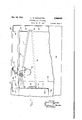
Dec. 23; 1941. w. EGGLESTON REFRIGERA'IING APPARATUS Filed Feb. 27, 1959 4 SheecS- Sheet l INVENTIOR W k- M J4 ATTORNEY Dec.23, 1941. Lw E GLESTON 2,266,965
REFRIGEBATING APPARATUS Filed Feb. 27, 193$) I 4 Sheets-Sheet 2 INVENTOR Lurk; W.
Ja ATTORNEY FIG-2 L. W. EGGLESTON REFRIGERATING APPARATUS Dec. 23, 1941.
Filed Feb. 27, 1939 4 Sheets-Sheet 3 INVENTORY .Xip ATTORNEY Patented Dec. 23, 1941 UNITED STATES PATENT OFFICE nar'aroanfifiifigirraaarus I i I Lewis W. Eggleston, Davison, Mich, asslgnor to Detroit Lubricator Company, Detroit, Mich, a
corporation of Michigan Application February 27, 1939, Serial N0. 258,597
23 Claims.
My invention relates generally to refrigerating apparatus and more particularly to those employing solid carbon dioxide as the cooling agent.
Much difficulty has been experienced in the past in keeping the desired low temperatures constant and evenly distributed throughout refrigerated compartments cooled by solid carbon dioxide due to the effect of the change in quantity as the solid carbon dioxide evaporates and escapes from the compartment.
An object of my invention is to provide a refrigerating system which is relatively uninfluenced by the quantity of solid carbon dioxide in the refrigerating system.
Another object of my invention is to provide an improved method of transferring heat from one compartment of a refrigerating apparatus to another compartment so .that stratification of temperatures therein is prevented.
Another object of my invention is to provide an improved cold control means whereby the heat abstracting effect of the solid carbon dioxide is controlled to prevent an undesirable low temperature in the refrigerated compartments.
The invention consists in the improved construction and combination of parts, to be more Fig. '7 is a view showing a modification of my invention.
Referring to the drawings by characters of reference the numeral I designates a rectangular metallic cabinet having end walls 2, 3, side walls 4, 5, a bottom wall 6 and a top wall I. A plu-.: rality of rectangular, metallic tubular members. 8 are located within and spaced from the walls The tubular members 8 prefof the cabinet I. I erably have their bottom ends closed and their top ends open and terminating below the top wall I of the cabinet 1. Each of a plurality of tubular throat members 9 has one end respectively secured in a suitable manner to the top end portions of the tubular members 8 and the top or other end portions extending through apertures in the top wall I of the cabinet'l so fully described hereinafter and the novelty of l the conduit system intact;
Fig. 3 is a view looking from the right end of the refrigerating apparatus with parts broken away to show the construction of the carbon dioxide compartment and one of the storage compartments;
Fig. 4 is a view of the weir member and accompanying cold controlling means;
Fig. 5 is a view of the weir member taken along the line 5-5 of Fig. 4 and looking in the direction of the arrows; v
Fig. 6 is a view of the cold controlling means taken along the line 5-6 of Fig. 4 looking in the direction of the arrows, and
looking in the direction of the arrows but with that their marginal portions III are secured in a suitable manner about upturned flange portions ll of the top wall I surrounding the apertures. The throat members 9 are preferably made of a suitable non-heat conducting material, such as rubber, so that heat transfer from the top wall I to the members 8 is held to a minimum. The tubular members 8 cooperate respectively with the throat members 9 to form;
a plurality of compartments I2, l3, l4 and IS. The open upper ends of the throat members 9 may be closed by suitable cover or lid members (not shown) toprevent external air from circulating into the compartments l2, l3, I4 and I5 and thereby further introducing heat to the compartments.
The compartments l2 and I3 are located ad-. jacent to but spaced from the end walls 2 and3v respectively, and the compartments l4 and i5 are secured together and located intermediate but spaced from the compartments l2 and I3. The adjacent top portions of the compartments l2 and i5, and I3 and I5, are secured together by means of U-shaped, metallic members I6, ll respectively. The metallic members l6, H are preferably made of'a metal having a high rate of heat conduction, such as copper or aluminunnso that heat may be conducted therethroughfrom; the compartments. i2, #3 to compartmenti 115, The adjacent walls of the compartments 14 l} are separated by a piece of insulating material;
l8, such as Celotex, with the exception of asmall; metallic connection at the top portions of their respective tubular members 8, at which. portions;- they are connected together by. means ofjriyets l9, intimately securing together the-tubular members, and a rectangular, metallic spacer,,.--,
top portions of the tubular members 8 together in heat exchange relation. The compartment I is the refrigerating compartment and is designed -for receiving suitable solid refrigerant medium such as solid CO2, while the compartments |2, l3 and I4 are the refrigerated compartments and are designed to receive perishable food products.
The compartments l2, l3 are also connected in heat exchange relation with compartment l5 by means of a refrigerant medium circulatory sys- The circulatory system 2| may comprise two interconnected conduits 22, 23 having upwardly extending end portions 22 23 respectively, secured to and communicatively connected to a hollow chambered member 24, to be described more completely hereinafter. The conduits 22, 23 preferably encircle the tubular members 8 of the compartments l2 and I3 respectively. The conduits 22, 23 have downwardly sloping portions 25, 26 respectively, adjacent the tubular member of the compartment l5, and upwardly sloping portions 21, 28 encircling the compartments |2, |3. The portions 21, 28 terminate in end portions 215, 28 respectively, secured to and communicatively connected with the member 24 to provide for gravity circulation of a liquid heat transfer medium. Secured to the top portion of the member 8 of compartment l2 and intermediate the compartment l2 and the end wall 2 is a sheet metal member 29 which is preferably of copper or aluminurn. The sheet metal member 29 extends downward along the side of and is secured to the tubular member 8 of compartment l2, and at its lower end portion turns outward and upward to receive, in good heat exchange relation, a conduit portion 29 of the upwardly inclined portion 21 of the conduit 22; A sheet metal member 30 similar to the member 29 is secured to the upper end portion of the tubular member 8 'of'compartment |3, intermediate the compartment I3 and the end wall 3, and extends downward and outward to receive, in heat exchange relation, a conduit portion 30 of the upwardly inclined portion 28 of the endless conduit 23 in a manner similar to that of the member 29. The portions of the inclined conduit portions intermediate the portions 29, 3|! and 21 28 respectively, are preferably secured in heat exchange relation to the adjacent portions of the tubular members 8 for additional cooling of the compartments |2, |3, respectively, and warming of the liquid mediumin the system 2|.
Secured in heat exchange relation to the bottom of the compartment l5 there is a sheet metal member 3| which is preferably of copper or aluminum. The member 3| is U-shaped and has a pair of parallel, upstanding leg portions '32, 33, one leg portion being on either side of the tubular member 8 of compartment I5. The upstanding portion 32 is intermediate the compartment I5 and the compartment l2, and the upstanding portion 33 is intermediate the compartment l5 and the compartment l3. The upstanding portions 32, 33 are each adjacent to but spaced from the vertical side walls of compartment |5 so that there is no direct conduction of heat to the upstanding portions 32, 33 except through the bot tom end wall of compartment l5. The upper end portions of the upstanding portions 32, 33 preferably turn outward and downward and receive, in heat exchange relation, conduit portions 32*, 33 of the portions 25, 26 respectively.
The refrigerant medium circulatory system 2| contains a liquid medium which preferably has a large coeflicient of expansion, such as acetone or methynol, so that the volume thereof will change materially with change in temperature. The refrigerant medium, which in this case is preferably solid CO2, in the compartment I5 extracts the-heat from the sheet'metal piece 3| through its conduction with the bottom wall of compartment 5. Due to the conductivity of the upstanding portions 32, 33 and the heat exchange relation with the bottom of the compartment l5, heat is extracted from the conduit portions 25, 25, respectively, and is-absorbed by the CO: to cause evaporation thereof. Cooling of the conduit portion 32' causes the portion of the liquid medium within the.conduit portion 32* to be lowered in. temperature so that its density is increased. Upon increase in density of the liquid medium portion, the liquid medium will flow downward within the conduit portion toward the portion 21, and as further liquid medium is cooled within the portion 32, the liquid within the conduit 22 will gradually circulate from the portion 32 downward and upward through the portion 21 to the member 24, from whence itflows downward again to the conduit portion 25.
I As the cool liquid medium flows through the conduit portion 29 it abstracts heat from the sheet metal member 29 which thereby increases the temperature of the liquid medium and lessens its density to aid in the natural circulation of the liquid medium through conduit 22. The sheet metal member 29 is thereby cooled by the circulating liquid medium so that it in turn cools the upper portion of the tubular member 8 of compartment l2 thereby refrigerating the compartment l2. In like manner the liquid medium is circulated through the conduit 23 removing heat from the compartment l3 and transferring it to the upstanding portion 33 to be finally transferred to the evaporating CO: within the compartment I5.
Circulation of the liquid'medium through the circulatory system 2| is controlled by means of a temperature control apparatus, generally desig;
nated 50, of which the hollow chambered member 24 comprises a portion. The member 24 is the highest point of the circulatory system 2| and comprises a pair'of oppositely disposed, downwardly projecting, tubular passageways 5|,- 52 which receive the upwardly extending portions 22, 23' respectively of the conduits 22, 23 respectively. The upwardly extending end portions 21, 28 are received in downwardly projecting, oppositely disposed, tubular passageways 53, 54 respectively, and which passageway s '53, 54 are respectively parallel to passageways 5|,, 52. The passageways 5|, 52 and 53, 54 form respectively the outlet and inlet chambers 55, 56 of the hollow member 24 and are preferably cast integral therewith. The outlet chamber 55 is separated from the inlet chamber'55 by a dam or weir member member-,5! actsupon a predetermined lpw-temperature of the liquid medium in the circulatory system 2| to interrupt the natural circulation of the liquid in the conduits 22, 23 so that heat may no longer be extracted from the compartments |2, 13 respectively, and transferred to the compartment |5 by the circulatory liquid medium.
A conduit I5 has one end I5 secured in fluid tight relation within a central aperture in the end wall 68, and the other end II secured in fluid-tight relation to the lower wall of member 24 and communicating with the outlet chamber 55 so that the liquid medium within the member equalize pressures within the member 24 and the tubular member 59 so that no liquid is caused to flow from or to the chamber 65 due to a difference of pressure between the adjustment member 58 and the system 2| so that the liquid level within the chamber 65 and the member 28 The member 59 is vertically secured to the side wall 5 of the cabinet I by means of a clamping strip 83 and rivets 84 so that it is in heat exchange relation therewith. The member 59 is also secured with respect to the member 24 so that the liquid displacement member 68 may be moved by means of the tubular member 68 through the horizontal plane which passes through the top tilled with a suitabl insulating material so that the rate of heat transfer from the cabinet to the compartments will thereby be lowered to a minimum. The compartments l2, l3 are particularly designed as a storage place for bulk ice cream, or the like. Compartment I4 is primarily designed for the storage of package goods, such as pre-packed ice cream. The compartment M will therefore preferably be run at a lower temperature than the compartments I2, l3 and its temperature is not adjustable by the temperature adjustment means 58. The compartment II is refrigerated by and is in good heat exchange relation with the refrigerated compartment l5 solely at the top portion thereof, through the rivets l8 and the rectangular metallic member. 28, but theinsulating material |'8 which is preferably about of an inch thick may however allow a small amount of heat to be transferred-from the compartment H to the compartment l5, throughout the entire height of the tubular member 8, but not such an amount as will unduly cool the compartment II. It is to be understood that if lower temperatures are desired the material |8 may be made thinner or omitted. A central threaded aperture in the end wall 8| is preferably closed by means of an externally threaded, bolt-like member 88 which is easily removable for adjustment. ,As is shown in Fig. 3 of the drawings, the adjust: ment means-88 is not connected to the top wall I of the cabinet I and access thereto is had through an aperture 81 in the top wall I. This aperture 81 is preferably closed by means of a removable plug member 88 screwed to a threaded flange portion 88.
The liquid heat exchange medium which wasthe system 2| the natural circulation of the liquid medium through the conduits 22, 23 is prevented by the dam 57 when the temperatures of the compartments l2, l3 are at or lowered below the desired operating temperature. When the temperature of the compartments l2, I3 is above the desired predetermined temperature, the liquid medium in the circulatory system 2 expands, due to the inherent characteristics of the liquid medium, and overflows the dam 51 so that natural circulation of the liquid medium through the conduits 22, 28 occurs. The particular con-- struction shown will also function to maintain.
the two compartments I2, l8 .at substantially the same temperature. As one compartment warms up beyond that of. the other for any cause whatsoever, the change in density of the liquid medium in the conduit system connected to the warmer chamber will be-greater than that of the other system. For example, suppose that the chamber |2 warms up more than the chamber IS. The density of the liquid medium in the conduit portions 32, 33 will be the same, both portions being maintained at substantially the same temperature by the compartment |5.- Chamber I! being at the higher temperature, conduit portion '28 will be at a higher temperature than 'of-the compartments l2, l8, and it will be conduit portion and therefore the density of the liquid medium in the portion 29 is less than that in portion 30. As the rate of circulation ofthe liquid medium in the conduits 22, 23 is proportional to the diflerentialin densities of the liquid medium therein, it is clearly seen that the liquid medium will circulate more rapidly in conduit 21 than in conduit 23, with a greater refrigerating effect; until the temperature of the container I2 is again brought substantially to that of the container I3. Because the U-shaped' member 3| is in heat exchange relation solely with the bottom of the compartment I5, it may be seen that the temperature thereof will be maintained substantially constant regardless of the quantity of solid CO2 which is contained within the refrigerated compartment I5. In this mannerthe variation in temperature of the tubular portions 32, 33, due to changes in quantity of the refrigerant medium, is prevented so that the. temperature of the liquid medium within the circulatory system 2I will be maintained at a substantially constant temperature regardless of the quantity of solid CO2 present.
Should it be desirable to change the predetermined temperature within the compartments I2,.
I3, the tubular member 68 may be rotated by means of a suitable tool, such as a screw driver, in the slot I4, so that the liquid displacement member 06 will displace more or less liquid depending upon whether it is desired to raise or lower the predetermined temperature to be maintained in the compartments I2, I3. It may readily be seen that if the liquid displacement member 66 is lowered so that it displaces more liquid within the chamber 65, the temperature at which the liquid medium must be lowered before the dam 51 will stop circulation within the circulatory system 2| will have to besubstantially lowered, and if the liquid displacementmember 56 is raised so that it displaces less] p the medium surrounding the cabinet I to the.
compartments I2, I3 isdependent upon the differential in temperature between the ambient temperature and the temperature-of the compartments I2, l3, and the ability of the circulating liquid medium to remove heat from the-compartments- I2, I3 is dependent upon the differential in temperature between the temperature of the liquid medium and the compartments I2, I3, it
will be readily understood by those skilled in the art that to maintain a predetermined desired temperature within the compartments I2, I3 with increasing ambient'temperature, the temperature of the liquid medium in the circulatory system II will have to be lowered in proportion to the increasing ambient temperature. In my invention, by maintaining the chamber 65 in heat exchange relation with the side wall 5 of the cabinet I, I compensate for changes in ambient temperature by raising or lowering the temperature at which the natural circulation of the liquid medium in the circulatory system 2| is prevented. It will be seen that as the temperature of the side wall 5' and chamber 65 rises, the volume which the liquid will occupy in the chamber 65 will be increased and some of the liquid in the chamber will flow through the conduit I5 to the circulatory system 2! and cause the average temperature thereof to be of necessity brought to alower temperature before the dam 51 will act to stop natural circulation through the conduit system 2|. Such a compensating effect acts in like manner as if an operator held a thermometer in one hand and manually adjusted the liquid displacement member with the other hand according to changes .in ambient temperature read on the thermometer. In like manner, when the ambient temperature lowers, the temperature of chamber will also be decreased so that liquid will be withdrawn through conduit 15 from the circulatory system 2|, thereby rendering higher the average temperature within the circulatory system at which the dam means 51 stops natural circulation. I therefore provide means for maintaining a constant compartment temperature regardless of ambient temperature or of the quantity of solid CO2 present. It is to be understood however that by varying the vo lume of chamber 05 I may over-compensate or undercompensate for changes in ambient temperature to secure any desired variation of compartment temperature with changes in ambient temperature.
In Fig. 7 I have shown a modification of my invention. The numeral I00 designates a substantially rectangular cabinet having an end wall I 0 I,
a front wall I02, and a top wall I03. Within the cabinet I00 and spaced from the walls thereof are two rectangular tubular members I04, I05. The tubular members I04, I05 have throat members I06, I01 respectively, secured in a suitable manner to the top endportions thereof. The throat members I06, I01 extend upward through apertures I08, I00 in the top wall I03 in a manner similar to the members 9 of Fig. 1. The tubular members I04, I05 are preferably made of a metal having good conductivity of heat and having their bottom end walls closed, and cooperate with the members I06, I01 respectively, to'foim compartments. The top portion of the tubular member I04 is connected by means of a metallic heat conducting member I09 to the top portion of the tubular member I05 so that the adjacent top portions of the tubular members I04, I05 are in heat exchange relation. The
compartment formed by the tubular member I05 receives'the solid refrigerant medium, which may be solid CO2, and the compartment formed by the tubular member I04 is adapted to receive food products to be refrigerated, and which may be bulk ice cream. A conduit member- 0 has its ends III, H2 connected together at their high points by a chambered member II3 so that the in heat exchangerelation to the upper end por-.
tion of .the tubular member I04 so that heat may be abstracted from the tubular member I04 and transferred to the conduit portion I IS. A second portion of the portion I I4, intermediate the portion I I6 and the end I I I, is preferably secured, as
by soldering, in heat exchange relation with the adjacent portion of the tubular member I04. An L-shaped heat transfer metal member IIO has its horizontal portion II9 secured to the bottom end of the tubular member I05 and its vertical portion I20 extending upward adjacent to but spaced from the side wall of the tubular member I05. The upper end of the vertical portion I20 is secured in heat exchange relation with a conduit portion I2I of the inclined portion I I5.
' A dam or weir means I22'is interposed in the path of the circulating fluid through the conduit member H and is positioned in the hollow chambered member H3, and operates to prevent natural circulation of liquid medium through the conduit member IIO upon a predetermined mean low temperature of the liquid medium, in a manner similar to the dam 51 of Fig. 5. A temper ature control apparatus I23, identical to the temperature control apparatus 58 of Fig. 4 is connected by means of conduits I24, I25 to the holunderstood that two independent systems, such as is shown in Fig. 7, could be substituted for the interconnected system of Fig. 1, and in such a case the temperature of the, compartments I2 and I3 thereof could be maintained at separate and independent temperatures at the will of the operator. I
I have invented and herein disclosed a new and improved refrigerating apparatus .which uses a solid refrigerant medium such as solid CO2, and
.low member I I3 in a manner similar to the way in which the conduits I5, I8 of Fig.4 connect the temperature control apparatus 58 to the chambered member 24. The member II3 is preferably spaced from the members I05, I I8 so that all of the conduit member III which is cooled by conduction and radiation is inclined downwardly and is conducive to natural circulation.
The 'operationof the modification 'shown in Fig. 7 is as follows: The evaporating solid C02 extracts heat from the horizontal portion N9 of the L-shaped member II8, thereby extracting heat from the vertical portion I20. The vertical portion I extracts heat from the portion I2I of 'the conduit member H0 and the liquid medium contained in the portion I 2I is cooled with a con sequent increase in-- density. The heavy liquid medium is caused to flow by gravity downward through the inclined portion I I5, after which the liquid medium flows upward through the inclined portion II 4, abstracting heat from the conduit .portion H6 and decreasing in density to further is maintained at substantially constant temperature by the solidCOa, which is in good heat ex-' change relation with the L-shaped member II8 solely at its. horizontal portion I I9, thevolume of the liquid medium within the conduit member 0 will be directly proportional to the temper ature of the tubular member I04 so that with constant setting of the temperature control apparatus I23, the average temperature of the tubular rounding the cabinet I00, will be maintained substantially constant.
The temperature control apparatus I23 is in heat exchange relation with the side wall I02 ofthe cabinet I00 so that its temperature is proportional to the ambient temperature surrounding the cabinet, in a manner-similar to that of the control apparatus 58 of Fig. 2. In this manner I vary-the average temperature of the liquid medium circulating in the conduit member H0 in accordance with'chan'ges in ambient temperature surrounding the cabinet I00 so that the interior 0f the tubular member I0 is maintained substantially constant in temperature regardless of the ambient temperature.
I have shown a single system for each solid CO2 member I04, with constant temperature surwhich is operableto maintain temperatures within the refrigerated compartments substantially constant as long as any refrigerant medium is present in the refrigerant compartment."
I have .also set forth an apparatus which maintains substantially even temperatures throughout the interior of the storage compartments,
due to the method of cooling the portions thereof, and-have shown compensating means wherebythe temperature'of certain of the storage compartments is maintained constant irrespective of changes in ambient temperature. Furthermore, I have invented a novel means for ad- 7 justment of the predetermined desired temperature at which I ments.
What I claim and desire to secure by Letters- Patent of the United States is:
1. In a refrigerating apparatus, a cooled compartment, a plate-like member having a high thermal conductivity, a cooling compartment spaced from said cooled compartment, heat transfer means including a heat" transferring liquid medium connecting a bottom portion of said cooling compartment to said plate-like member, said plate-like member being on the top.
portion of the wall of said cooled compartment furthest away from said cooling compartment. and means for controlling the rate of heat transfer from said cooled compartment" to said cooling compartment.
2. In a refrigerating apparatus, a cooled com-j partment, a cooling compartment spaced from said cooled compartment, heat transfer means connecting a bottom portion of said cooling compartment to the top portion of said cooled compartment, said top portion being onthe wall of said cooled compartment furthest away' from said cooling compartment, and means separate from said transfer means'connectingthe adiacent top portions ofsaid compartments in heat exchange relation.
3. In a refrigerating apparatus, a cooled compartment having a top portion, a cooling compartment having top and bottom portions, conduit means adapted for natural convection flow of a liquid in heat exchange relation with said top portion of said cooled compartment and said bottom portion of said cooling compartment, a liquid medium in said means and having a substantial coefficient of expansion for flow through said means, and means separatefrom said coriduit means connecting said compartments in heat exchange relation at' said top portions 4. In a refrigerating apparatus, a conduit sys-- tem adaptedfor gravity circulation of a liquid therethrough and having a high point, a cooling compartment having a bottom portion, a cooled compartment having a top portion, a portion of said conduit system being in heat exchange re-' lation with said top portion of said cooled com-- partment, a second portion of said conduit system being in heat exchange relation 'withsaid containing compartment, but it to be distinctly maintain certain of the compart- 6 bottom portion of said cooling compartment; a liquid medium having a substantial coeflicient of expansion upon increase of,temperature, a weir means at saidlhigh point that said medium is prevented from circulation through said conduit system when said medi is below a predetermined average minimum temperature, and reservoirmeans sensitive to ambient temperature surrounding the apparatus and operable to vary the quantity of said medium so that said cooled compartment is maintained at a substantially constant predetermined temperature'irrespective of ambient temperature.
5. A refrigerated apparatus comprising a cooled compartment having a top portion, a cooling compartment having a bottom portion, conduit means in heat exchange relation with said top portion of said cooled compartment and said bottom -portion of said cooling compartment, a liquid medium in said, means having a substantial coefllcientof expansion, reservoir means sensitive to ambient temperature surrounding the apparatus and communicating' with said'conduit means and controlling the quantity of said medium in said conduit means so that upon a predetermined low average temperature of said medium said high point is operable to regulate the flow of said medium in said conduit means, and a second cooled compartment adjacent said cooling compartment,
said second compartment being in good heat exchange relation with the top portion solely of said cooling compartment.
6. In a refrigerating apparatus, a plurality of cooled compartmentseach having top portions,
a cooling compartment having a] bottom portion,
said top portions being on the side of said cooled compartments furthest away from said cooling of said cooling compartment and having a high point, a second conduit means in heat exchange relation with said top portion of another of said cooled compartments and said bottom portion of said cooling compartment, said conduit means being interconnected at said high point to forma closed conduit system, a liquid medium in said system and having a substantial coefficient of expansion, and dam means at-said high point so that expansion of said medium due to a temperature increase thereof above a predetermined average temperature in either of said conduit means will cause said expanded medium to overflow said dam means and circulate through said system, said medium when at an average temperature .below said predetermined minimum temperature contracting and thereby being prevented from overflowing said dam means.
7. In a device of the character described, a cooled compartment having top portions, a cooling compartment having a bottom portion and a top portion, a conduit means, one of said cooled compartment top portions being on the side of said cooled compartment furthest away from said cooling compartment, the other of said cooled compartment top portions being adjacent said, cooling compartment top portion, means having a high rate of heat transfer in'heat exchange relation with said conduit means, said transfer means being in heat exchange relation with said one top portion, a second means having a high'rate of heat transfer in heat exchange relation with said conduit means. said second,
transfer means being in heat exchange relation aacaees with said bottom portion, a fluid heat exchange medium insaid conduit means operable to transfer heat from said flrst transfer means to said second transfer means, and means connecting said cooling compartment top portion and said other top portion in heat transfer relation.
, 8. In an apparatus of the character described, a container operable to receive solid carbondioxide, a storage container operable to store'a substance at a predetermined low temperature, a liquid medium, conduit means containing said medium and adapted for natural convectioncirculation of said medium, a metallic plate having one end portion secured in heat exchange relation to said conduit means to remove heat from said medium and having the opposite end 'porconstant temperature of said storage compart- Y ment, and metallic plate means joining the adjacent top portions of said containers in heat exchange relation.
9. A refrigerating apparatus comprising a compartment to be refrigerated, a continuous conduit means having a portion thereof in heat exchange relation to said compartment, a liquid in said conduitm ans establishing a closed liquid circuit and operabletoabstract heat from said compartment at said portion, means to abstract heat from said liquid at another portion of said conduit means, said liquid being expansible and'contractible in accordance with the temperature thereof, said conduit means having a high point effective upon contraction of the liquid to interrupt the liquid circuit, means respon-' sive to ambient temperature external of said refrigerated compartment to regulate the temperature at which said high point becomes effective, and means protecting said responsive means Y from temperatures in said refrigerated compartment.
l0. In an enclosed fluid system adapted for natural convection cooling of a space, a liquid medium having a substantial coeflicient of expansion, a conduit system having a high point, said system having a heat abstracting portion of relatively high temperature and having a radiating'point of low temperature relative to said abstracting portion, dam. means at said high point, said liquid medium being operable upon an increase in temperature to increase in volume and overflow said dam means so that said liquid medium will flow by natural convection 2,266,965 1 temperature relative to said abstracting portion,
dam means at said high point-said liquid medium being operable upon an increase in temper-' ature to increase in, volume and overflow said dam means so that said liquid medium will flow by natural convection in said conduit system,
- ally operable means operable on said reservoir means to regulate the quantity of said medium therein.
12. In an apparatus of the character described, a receptacle for the storage of a cooling medium and having a face with a plane surface, a cooled receptacle adjacent said first-named receptacle and having a face with'a plane surface, said plane surfaces being spaced from and parallel to each other, means having a high rate of heat transfer connecting said plane surfaces at the top adjacent portions thereof, and means having a relatively low rate of heat transfer separating the remainder of said plane surfaces, said first-named means and said second-named means being so interrelated that said secondnamed receptacle is cooled by said first-named receptacle substantially without temperature stratification within said second-named receptacle.
13. In an apparatus of the character described, comprising a casing having a passageway therethr'ough, a weir means having a top face in said passageway, a chambered means,'
scribed, comprising a casing having a passageway therethrough, a weir means having a, top face in said passageway, a cylindrical member having upper and lower end walls, said end walls having apertures therethro'ugh, conduit means having one and secured in said lower end wall aperture and communicating with the interior of said cylindrical member and having the other end thereof communicating with said passage-. way below the level of said top face, a second conduit means having one end secured within an aperture through said cylindrical member. and connecting the top portion of said cylindrical member tosaid passageway above the level of said top face, a fluid displacing means having an upwardly extending portion, and a plate-like ,member having an aperture therethrough, said extending portion extending through said aperture and being pperable to position said displacing means relative to said top face for varying the effective capacity of said cylindrical 'mem-' ber below said top face..
17. In an apparatus of the character described, comprising a casing having a passagei means having one end secured in said lower end wall aperture and communicating with the interior of said cylindrical member and having the other end thereof communicating withsaid passageway below the level of said top face, a second conduit means having one end secured within an aperture through said cylindrical member 7 and connecting the top portion of said cylindriconduit means connecting the bottom portion of said chambered means to said passageway below the level of said top face, a second conduit means connecting the top portion of said chambered means to said passageway above'the level of said top face, and means for varying the effective capacity of said chambered means belowthe level of said top face.
face in said passageway, a chambered means,
conduit means connecting the bottom portion of said chambered means to said passageway below the level of said top face, a second conduit means connecting the top portion of said ch=am beredmeans'to said passageway above the level of said top face, and means adjustably supported within said chambered means for varying the effective capacity of said chambered "means below the level of said top face.
15. In an apparatus of the character described, comprising a casing having a passageway therethrough, a weir means having a top face in said passageway, a chambered means, conduit means connecting the bottom portion of said chambered means to said passageway below the level of said top face, a second conduit means connecting the top portion of said chambered means to said passageway above the level of said top face, liquid displacing means having 7 an upwardly extending portion, and a platelike member having an aperture therethrough,
cal member to said passageway above the level of said top face, a fluid displacing means having to be rotated within said screw-threaded aperture and being operable to position said displacing means relative to said top face for varying the effective capacity of said cylindrical member below said top face, and means for preventing unwanted rotation of said section.
18. m a refrigerating apparatus, a conduit system adapted for gravity circulation of a liquid therethrough and having a high point, a
cooling compartment having a bottom portion, a cooled compartment having a top portion, a
portion of said conduit system being in heat exchange relation with said top portion of said cooled compartment, a second portion of said conduit system being in heat exchange relation with said bottom portion of said cooling compartment, a liquid medium having a substantial coefficient of expansion upon increase of temperature, means at said high point so that said medium is prevented from circulation through said conduit system when said medium is below I a predetermined average minimum temperature,
and means sensitive to'ambient temperature surrounding the apparatus and operable to vary the quantity of said medium so that said cooled compartment is maintained at'a predetermined temperature relative to said ambient temperature.
19. In an apparatus of the character described, a container operable to receive solid carbon dioxide, a storage container operable to store a substance at a predetermined low temperature, a liquid medium, conduit means containing said medium and adapted for natural convection circulation of said medium, a metallic plate having one end portion secured in heat exchange relation to said conduit means to remove heat from said medium and having the opposite end portion thereof secured in heat exchange relation with said first-named container, a second metallic plate having one end portion secured in heat exchange relation to said conaaaaees substantially parallel to one of said outlet apertures, the other of said inlet apertures being substantially parallel to the other of said outlet apertures, and dam means within said chamber and forming a barrier over which the liquid must flow when flowing from said inlet apertures to said outlet apertures.
22. In an apparatus of the character -described, comprising a casing having a passageduit means and having the other end portion seber, and dam means positioned within and extending upwardly from the bottom wall of saidchamber, said dam means extending across the interior of said member transversely to the flow passageway between said inlet and said outlet' and forming a barrier over which the liquid must flow when flowing from said inlet aperture to said outlet aperture. a
21. In an apparatus for controlling the flow 0 liquid, 9, member having a chamber, said member having a pair of oppositely disposed upwardly directed inlet apertures leading into said chamber and a pair of oppositely disposed downwardly directed outlet apertures leading from said chamber, one of said inlet apertures being way therethrough, a weir means having a top face in said passageway, a chambered means, conduit means connecting the bottom portion of said chambered means to said passageway below the level of said top face, and a second conduit means connecting the top portion of saidchambered means to said passageway above level of said top face.
23. In an apparatus for controlling the flow ,of
the
liquid, a member having an inlet chamber and an having a second portion opening outlet chamber, said member having an upwardly directed inlet aperture leading to said inlet chamber and a downwardly directed outlet aper I ture leading from said outlet chamber, partition means within said member and forming a barrier over which liquid must flow from said inlet chamber to said outlet chamber, a second member for containing liquid, a conduit means-having one portion opening into one of said chambers below the top surface of said partition means and having a second portion opening into said secondmember, and a second conduit means having one portion opening into said first-named member above said partition top surface and into said second member.
' LEWIS W. EGGLESTON.
Priority Applications (1)
| Application Number | Priority Date | Filing Date | Title |
|---|---|---|---|
| US258597A US2266965A (en) | 1939-02-27 | 1939-02-27 | Refrigerating apparatus |
Applications Claiming Priority (1)
| Application Number | Priority Date | Filing Date | Title |
|---|---|---|---|
| US258597A US2266965A (en) | 1939-02-27 | 1939-02-27 | Refrigerating apparatus |
Publications (1)
| Publication Number | Publication Date |
|---|---|
| US2266965A true US2266965A (en) | 1941-12-23 |
Family
ID=22981277
Family Applications (1)
| Application Number | Title | Priority Date | Filing Date |
|---|---|---|---|
| US258597A Expired - Lifetime US2266965A (en) | 1939-02-27 | 1939-02-27 | Refrigerating apparatus |
Country Status (1)
| Country | Link |
|---|---|
| US (1) | US2266965A (en) |
Cited By (1)
| Publication number | Priority date | Publication date | Assignee | Title |
|---|---|---|---|---|
| US2724951A (en) * | 1953-03-27 | 1955-11-29 | Arce Ambrosio | Liquid cooling device |
-
1939
- 1939-02-27 US US258597A patent/US2266965A/en not_active Expired - Lifetime
Cited By (1)
| Publication number | Priority date | Publication date | Assignee | Title |
|---|---|---|---|---|
| US2724951A (en) * | 1953-03-27 | 1955-11-29 | Arce Ambrosio | Liquid cooling device |
Similar Documents
| Publication | Publication Date | Title |
|---|---|---|
| US2345505A (en) | Refrigeration | |
| US1980089A (en) | Refrigeration | |
| US2605621A (en) | Series connected ice maker and water cooler | |
| US1926384A (en) | Refrigerating apparatus | |
| US3783633A (en) | Co{11 {11 {0 refrigeration system | |
| US2261681A (en) | Refrigeration | |
| US2266965A (en) | Refrigerating apparatus | |
| US2506840A (en) | Water cooler with thermal insulated water cock | |
| US2563975A (en) | Two temperature refrigerator | |
| US2511127A (en) | Refrigerator cabinet having a movable evaporator | |
| US2107076A (en) | Refrigerating apparatus | |
| US2219789A (en) | Refrigerator | |
| US2055158A (en) | Method and apparatus for refrigeration | |
| US2154299A (en) | Refrigerator | |
| US2166506A (en) | Refrigerating apparatus | |
| US2504372A (en) | Liquid cooler | |
| US2482222A (en) | Two-temperature refrigerating means | |
| US2777297A (en) | Two evaporator refrigerating system | |
| US2168537A (en) | Refrigerating apparatus | |
| US1887693A (en) | Refrigerating apparatus and method | |
| US2330917A (en) | Refrigerating apparatus | |
| US2215192A (en) | Cooler apparatus | |
| US2702457A (en) | Evaporator structure in absorption refrigeration | |
| US2768510A (en) | Plural temperature refrigeration apparatus | |
| US2055994A (en) | Refrigerating apparatus |