US2261160A - Mining apparatus - Google Patents
Mining apparatus Download PDFInfo
- Publication number
- US2261160A US2261160A US246509A US24650938A US2261160A US 2261160 A US2261160 A US 2261160A US 246509 A US246509 A US 246509A US 24650938 A US24650938 A US 24650938A US 2261160 A US2261160 A US 2261160A
- Authority
- US
- United States
- Prior art keywords
- cutting
- dislodging
- coal
- base
- bars
- Prior art date
- Legal status (The legal status is an assumption and is not a legal conclusion. Google has not performed a legal analysis and makes no representation as to the accuracy of the status listed.)
- Expired - Lifetime
Links
- 238000005065 mining Methods 0.000 title description 26
- 238000005520 cutting process Methods 0.000 description 151
- 239000003245 coal Substances 0.000 description 121
- 230000007246 mechanism Effects 0.000 description 41
- 239000007787 solid Substances 0.000 description 24
- 238000011068 loading method Methods 0.000 description 16
- 230000033001 locomotion Effects 0.000 description 12
- 239000012634 fragment Substances 0.000 description 10
- 230000008933 bodily movement Effects 0.000 description 9
- 230000003028 elevating effect Effects 0.000 description 8
- 230000009471 action Effects 0.000 description 5
- 238000010276 construction Methods 0.000 description 3
- 230000000694 effects Effects 0.000 description 3
- 230000010006 flight Effects 0.000 description 3
- 239000000463 material Substances 0.000 description 3
- 238000010408 sweeping Methods 0.000 description 3
- 238000012840 feeding operation Methods 0.000 description 2
- 230000004048 modification Effects 0.000 description 2
- 238000012986 modification Methods 0.000 description 2
- 239000010454 slate Substances 0.000 description 2
- 230000015572 biosynthetic process Effects 0.000 description 1
- 238000005422 blasting Methods 0.000 description 1
- 230000000052 comparative effect Effects 0.000 description 1
- 230000000994 depressogenic effect Effects 0.000 description 1
- 238000006073 displacement reaction Methods 0.000 description 1
- 239000002360 explosive Substances 0.000 description 1
- 239000012530 fluid Substances 0.000 description 1
- 239000007788 liquid Substances 0.000 description 1
- 230000013011 mating Effects 0.000 description 1
- 238000004804 winding Methods 0.000 description 1
Images


Classifications
-
- E—FIXED CONSTRUCTIONS
- E21—EARTH DRILLING; MINING
- E21C—MINING OR QUARRYING
- E21C27/00—Machines which completely free the mineral from the seam
- E21C27/10—Machines which completely free the mineral from the seam by both slitting and breaking-down
- E21C27/14—Machines which completely free the mineral from the seam by both slitting and breaking-down breaking-down effected by force or pressure applied to side of slit, e.g. by wedges
- E21C27/16—Machines which completely free the mineral from the seam by both slitting and breaking-down breaking-down effected by force or pressure applied to side of slit, e.g. by wedges with means for both slitting and breaking-down
Definitions
- This invention relates to mining apparatus, and more particularly to improvements in coal mining apparatus of the combined cutting and loading type for cutting the solid coal, dislodging the cut coal from the solid and loading the dislodged coal.
- An object of the present invention is to provide an improved coal mining apparatus embodying means for completely removing the solid coal from its natural bed wholly without the use of explosives or other blasting apparatus, and for loading the dislodged coal. Another object is to provide an improved coal mining apparatus of the combined cutting and loa-ding type having improved means for cutting and dislodging the coal. A further object is to provide an improved cutting, dislodging and gathering means having embodied therein improved means for retaining the coal to be gathered in the path of the gathering means, together with improved means for delecting the coal from the gathering means as it is received by the conveying means of the apparatus. Yet another object is to provide an improved coal cutting and loading apparatus having improved conveying means associated with the gathering mechanism in an improved manner.
- a further object is to provide an improved apparatus of the above character having novel combinations and arrangements of parts whereby eX- treme compactness as well as relatively great flexibility are attained.
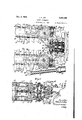
- Fig. 1 is a top plan view of a coal mining apparatus constructed in accordance with the prewith parts shown in elevation, showing the parts in an elevatedposition.
- Fig. 5 is an ,enlarged horizontal sectional View taken substantially on line 5-5 yof Fig. 2.
- Fig. 6 is a vertical sectional View taken substantially on line 6-6 of Fig. 5'.
- Fig. '7 is a cross sectional View taken substantially on line 1-1 of Figs. 1 and 6.
- Fig. 8 is an enlarged cross sectional view taken substantially on line 8-8 of Fig. 1.
- Fig. 9 is a View in longitudinal vertical section taken substantially on line 9-9 of Figs. 1 and 8, with the cutting and dislodging chainspartially broken away.
- Fig. 10 is a horizontal sectional view taken substantially on line IO-lll of Figs. 8 and k9.
- Fig. 11 is an enlarged cross sectional view taken substantially on linev l I-Il of Fig. 3.
- Fig. 12 is a horizontal sectional view taken substantially on line lZ-IZ of Fig. 3.
- Fig. 13 is a plan view of the bottom skid with the superstructure removed therefrom.
- Fig. 14 is a cross sectional view taken substantially on line
- Fig. 15 is a perspective view of a section of one of the cutting and dislodging chains, showing the coal breaking wedges.
- Fig. 16 is a detail view of one of the outer coal breaking wedges.
- Fig. 17 is a detail view o i one of the inner coal breaking wedge plates ⁇ Fig. 18 is an enlarged transverse vertical sectional view taken substantially onY line IS-I of Fig. 2.
- Fig. 19 is a horizontal sectional view stantially on line
- Fig. 20 is a transverse vertical sectional view taken substantially on line 28-20 of Fig. 19.
- Fig. 21 is a diagrammatic View illustrating the hydraulic uid system.
- Fig. 22 is a horizontal sectional view' illustrating the valve box structure.
- Fig.v 23 is a vertical sectional view taken substantially on line 23-23 of Fig. 22.
- Fig. 24 is a cross sectional view taken subtaken substantially on 1ine ⁇ 24-24 of Figs. 22 and 23.
- Fig. 25 is a diagrammatic plan view through a mine entry showing the improved mining apparatus in operative cutting and dislodging positions with respect to the working face.
- Fig. 26 is a view similar to Fig. 24 showing the position of the cutting and dislodging mechanism at the completion of the swinging cut.
- Fig. 27 is a diagrammatic side View illustrating the mining apparatus with the cutting and dislodging mechanism in operative position at the iioor level in a mine passage.
- Fig. 28 is a view similar to Fig. 27 showing the cutting and dislodging mechanism in its elevated position above the mine floor.
- Fig. 29 is a view similar to Fig. 7 showing a modified form of construction.
- a coal mining apparatus of the combined cutting and loading, oor type mounted on a bottom skid for sliding movement on its own bottom over the mine oor, although it will be evident that the apparatus, if desired, may be truck mounted or tractor-tread mounted.
- cutting and dislodging mechanism is associated with conveyor mechanism for cutting the solid coal, dislodging the cut coal from the solid and moving the dislodged coal toward the receiving portion of the conveyor mechanism, and the conveyor mechanism receives the broken coal and moves the latter away from the coal face toward an elevated discharge position at the rear end of the apparatus.
- the reference character I generally designates the cutting and dislodging mechanism and 2 the associated conveyor mechanism.
- the apparatus more speciiically comprises a bottom skid plate 3 adapted to rest upon and slide in any direction over the mine floor, and this skid platehas extending lengthwise thereof parallel guide members 4, 4 providing longitudinal guideways in which are slidably mounted lateral guides 5, 5 formed integral with the lower plate of a main frame 6 of the apparatus.
- the main frame 6 has, at its rearward end, upstandingside projections 'I on which are pivotally mounted at 8 on a horizontal shaft extending transversely of the main frame, an upper arm or link 9, while pivotally mounted on a parallel axis at I near the bottom of the main frame in advance of the pivotal axis 8, is a pair of parallel bottom arms 6, as shown in Fig. 12.
- the forward ends of the r parallel arms 9 and II are pivotally connected on parallel axes at I3 and I4, respectively, to a support I providing a connection between the forward ends of the upper and lower arms.
- Mounted on and projecting forwardlyfrorn the support I5 is the casing of a horizontal motor I6 having its power shaft I'I horizontally disposed and extending longitudinally of the apparatus.
- the motor has a front head I8 having secured thereto a front support I 9, and this front support and the casing of the motor are rigidly iixed to the rear support I5, as by parallel tie bolts 20, 2D, in the manner clearly shown in Fig. 4.
- the front support I9 is made up of two parts suitably secured together, as by bolts, and provides forwardly projecting, laterally spaced circular bearing supports 2
- the two cooperating sets or gangs of cutting and dislodging bars swing about parallel vertical axes arranged at the opposite sides of and spaced equidistantly from the longitudinal vertical center of the apparatus, and these cutting and dislodging bars are operative to swing about their pivotal axes from a right angle alined position toward one another 'across the forward end of the apparatus to a position in adjacency near the longitudinal vertical center of the apparatus, each through an angle of substantially more than the axes of swinging movement of the cutting and dislodging bars being located in adjacency to but in advance of theforward receiving portion of the conveyor mechanism.
- the cutting and dislodging chains are of similar design and each comprises a series of chain blocks 3I pivotally connected together by strap links 32, and each of the chain blocks is substantially U-shaped in cross section, as clearly shown in Fig. 9, and the arms 33, 33 of the U each support a lug 34 having a socket for receiving a cutter bit 35.
- the cutters on the chain blocks are arranged on the arms thereof at the opposite sides of the chains, thereby to provide parallel series of cutters.
- coal breaking wedge plates 31 are arranged on the opposite sides of the bit-receiving lugs of the chain links, while on one of the chain links of each chain, on the inner sides of the arms of a U-shaped block.
- the coal breaking wedges and wedge plates act automatically periodically to break down sections or fragments of the projecting coal between the slots as cutting progresses.
- the cutter chain structure is generally similar in design to that disclosed in my Patent No. 2,057,684, patented October 20, 1936, further description thereof is herein considered unnecessary.
- the driving means for the cutting and dislodging chains comprises a spur gear 46 meshing with spur gears 4I and 42, arranged on parallel longitudinally extending axes (see Fig. 5) and having their hubs suitably journaled in bearings supported by the front support I9, while arranged coaxially with these gears and likewise suitably journaled within the front support are shafts 43 and 44 connectible in driving relation with the hubs of the spur gears 4I vand 42 by -sliding jaw clutches 45 and 46 respectively, each having an operating lever 41 conveniently located at the top of the iront suplport, as shown in Fig. 1.
- bevel gears 48 and 49 meshing with bevel gears 5U and 5I respectively. These bevel gears are driven in relatively opposite directions by the bevel gears 48 and 49 respectively and have their hubs keyed to alined horizontal shafts 52 and 53. These shafts are arranged with their axes extending transversely of the iront support I9 and have secured thereto and drive worms 54 meshing with worm wheels 55 keyed to vertical shafts 56 and 51 respectively.
- These shafts are arranged with their axes coincident with the pivotal axes of the bar hanger frames 21, and have respectively keyed thereto and drive chain sprockets 58 and 59 engaging the cutting and dislodging chains 3i) guided about the margins of the cutter bars.
- the cutting and dislodging chains may be driven in unison by the motor I6 through the spur gears 40, 4I, 42, bevel gears 48, 59 and 49, 5I, alined shafts 52, 53, worm gearings 54, 55, vertical shaft-s 56, 51 and the chain sprockets 58, 59; and when the clutches are released, the cutting and dislodging chains may remain idle during running of the motor.
- the cutting and dislodging chains of the sets of bars may be independently driven. It will be evident that these superimposed chain structures comprise pairs of superimposed cutting and dislodging bars mounted on the opposite sides of the front receiving portion of the conveying mechanism to swing about parallel vertical axes, and these cutting and dislodging bars are operable,
- extend through a major portion of the length and are secured to the inner adjacent surfaces of the bars, and the upright flanges of these angle members overlap one another, in the manner shown, at each side of the bars.
- Bolt and slot connections 62 are provided for securing these overlapping flanges together against relative vertical displacement while permitting relative longitudinal adjustment therebetween, so as to permit relative endwise adjustment of the bars relative to their hanger frames during tightening of the cutting and dislodging chains.
- the boxlike obstructions between the superimposed bars of the cutting and dislodging chains are omitted to permit the cutting and dislodging chains of the top bars to cut and dislodge coal above al slate band and the cutting and dislodging chains of the bottom bars to cut and dislodge the coal beneath the slate band.
- the structure of the cutting and dislodging mechanisms is identical to that described above.
- This deiiector means comprises a deiiector member 69 secured to the top of the iront support I9 and arranged between the rearward ends of the sets of gangs of cutting and dislodging bars, as shown mos-t clearly in Figs. 1 land 3, and this deector member has a generally U-shaped deector portion 10 projecting in the spaces between the arms of the U of the U-shaped cutter blocks of the top chains 36 of the cutting and dislodging bars.
- This defiector member prevents the dislodged coal from being thrown back by the cutter chain over the top of the front support and confines the dislodged coal in the path of the receiving end of the conveyor.
- the circular bearing supports 2I, 2I of the front support I9, as shown in Figs. 3, 5 and 6, serve as deflector means for deflecting the dislodged coal from the space between the top and. bottom cutting and dislodging chains, and also directthe dislodged coal toward the receiving end of the conveyor.
- Cooperating with the top deilector member are deilector members 1I, 1I secured, as shown in Figs.
- a hydraulic elevating cylinder 16 pivotally mounted on a horizontal pivot shaft 15 alined with the pivot shafts I2, I2 for the lower parallel arms II, II is a hydraulic elevating cylinder 16, herein arranged midway between the lower arms and containing a reciprocable piston 11 having its piston rod 18 extending upwardly through the packed front head of the cylinder, the forward extremity of the piston rod being pivotally connected to the rear connecting support I5 on an axis coincident with the axis I3 of pivotal connection of the upper arm 9 with the support I5, in the manner shown in Fig. 4.
- the parallel arms 9, have their axes of pivotal connection with the main frame 6 and the connecting support l5 equi-distantly spaced so that these arms cooperate to provide a parallel motion mechanism for the cutting and dislodging bars, so that as the arms are swung upwardly about their pivots, the cutting and dislodging bars are always maintained in horizontal cutting and dslodging position.
- hydraulic pressure is supplied to one end or the other of the elevating cylinder 1.6, the piston 11 is moved with respect to the cylinder to effect swinging of the parallel arms 9, either upwardly or downwardly about their pivotal axes with respect to the main frame 6 of the apparatus, thereby to vary the elevation of the cutting and dislodging bars.
- the swinging means for the cutting and dislodging bars comprises brackets 19 secured, as shown in Figs. 5 and 7, respectively, tothe sets of superimposed cutting and dislodging bars 28, 28, and these brackets project laterally outwardly from the upper and lower bars between the upper and lower cutting and dislodging chains in the manner dis closed.
- Pivotally connected at 80 to the outer ends of the brackets are piston rods 8
- the swinging cylinders 83 in this instance, have formed integral with their rear heads projecting bearing lugs 85 pivotally mounted on pivot pins 86 supported within lateral lugs 81 formed integral with the rear connecting support l5.
- the cutting and dislodging bars may be swung horizontally about their pivotal axes either inwardly or outwardly with respect to each other.
- the means for supplying hydraulic pressure to the elevating and swinging cylinders will later be described.
- the conveyor mechanism 2 is mounted upon the main frame of the apparatus and is herein of a well known type comprising two parallel troughs 88 positioned in substantially the same transverse planes at the opposite sides of the main frame 6 and secured to the latter by angle members 89, and each having an upright outer side wall 90.
- secured to the adjacent side of the main frame and providing a guideway 92 for the endless drive chain 93 of the conveyor.
- This drive chain comprises two-part chain blocks 94 connected together by jointed strap links 95, and the chain blocks have formed thereon conveyor flights 96 adapted to engage the material in the troughs at one side of the conveyor and move it therealong.
- the chain links and Straps are connected together by suitable pairs of horizontal and vertical pintles to render the chain flexible in both horizontal and vertical planes and to permit the chain to follow the contour of the conveyor guideways. It is to be understood, however, that any other type of chain which is adapted to flex in horizontal and vertical planes may be substituted for the above described one without departure from the spirit of the invention.
- the flights may be of any preferred form adapted to move the material to be loaded along the trough of the conveyor. Preferably I have formed these flights integral with the mating parts of the chain blocks which are secured together, as by rivets 91.
- the conveyor troughs 88 arranged at the opposite sides of the main frame 6 each comprise a horizontal rearward portion 98 and a horizontal bottom front portion 99, these horizontal portions being connected together by an inclined portion
- the driving means for the conveyor comprises a motor
- 03 meshing Keyed to the inner end of the motor power shaft is a spur gear
- 08 is herein preferably arranged with its axis coincident with the motor power shaft axis and in parallelism with the shaft
- 08 is a bevel gear
- 2 is suitably journaled within the main frame and has keyed thereto and drives a sprocket
- 0 is connectible by a jaw clutch
- the jaw clutch comprises a sliding clutch member
- Means for moving the apparatus bodily over the mine oor during maneuvering of the machine, comprising a cable winding drum
- Formed integral with the upper drum flange is a spur gear
- 22 is journaled within bearing sleeves
- 29 Connected to the upper end of the drum shaft
- This handle is pivoted to swing in a vertical direction, and when depressed is engageable with stop lugs
- Wound on the drum is a feed cable 3
- hydraulically operated means is provided to move with a walking action the apparatus over the mine floor and for feeding the main frame 6, together with the cutting and dislodging bars supported thereby, rectilinearly back and forth relative to the bottom skid 3.
- the feeding means for effecting rectilinear feed is arranged longitudinally beneath the main frame in adjacency to the bottom skid and comprises a pair of reciprocable hydraulic cylinders
- 35 Contained in these cylinders are pistons
- the main frame 6, together with the cutting and dislodging bars supported thereby may be slid back and forth along the guideways relative to the bottom skid.
- 32 extend longitudinally in the spaces between the lower parallel arms I, and the centrally located elevating cylinder 16, so that extreme compactness is obtained when the parts are in their lowered position on the skid.
- the bottom of the main frame is formed with a centrally located, longitudinal guiding slot
- the walking jacks are, in this instance, three in number and are designated
- comprises a vertical cylinder
- the piston rod has a bottorn abutment surface engageable with the mine floor.
- the skid is centrally slotted at
- 43 each comprise, as shown most clearly in Fig.
- the apparatus may be movedA over the mine floor with a walking action by successively feeding the main frame relative to the skid, relieving the skidof the weight of the main frame, feeding the unweighted skid relative to the main frame and thereafter lowering the main frame onto the skid.
- the means for supplying hydraulic pressure to the feed and jack cylinders will later be described.
- thebottom skid has extending along the sides thereof at its forward portion vertical retaining walls
- a pump I6! having its intake submerged within the liquid in the reservoir and driven by a shaft
- the pump discharge is connected by a conduit
- the valve box has formed therein a series of horizontal bores containing slide valves of the balanced-spool type. Extendingr longitudinally of the valve box and communicating with the supply passage
- 61 Communicating with the' ends of the valve bores are discharge passages
- the slide valves are respectively designated
- 66 is connectible by a manually operable by-pass valve 11 to a passage
- 12 controls the supply of hydraulic pressure to the feed cylinders
- 13 controls the supply of hydraulic pressure to the elevating cylinder 16 and has its bore connected through conduits
- 14 controls the supply of hydraulic pressure to the left hand bar swinging cylinder 83 and has its bore connected through conduits
- is connectible through an automatic by-pass valve
- the apparatus may be moved bodily over the mine floor during maneuvering of the apparatus, at a relatively high moving speed by the feed drum
- the cutting and dislodging bars 28, 28 are in their oppositely extending right angle position at the opposite sides of the apparatus with their longitudinal axes in substantial alinement, When the cutting and dislodging bars are in the full line position indicated at A in Fig.
- the cutting and dislodging chains completely cut away or disintegrate the coal from the solid between the upper and lowermost limits of the chains.
- the conveyor may discharge the coal into a suitable receptacle or onto a conveyor mechanism in a well known manner.
- Hydraulic pressure is then supplied to the feed cylinders
- 43 are operated to raise the main frame from the skid to relieve the latter of the weight of the apparatus, and the feed cylinders
- 32 are then again operated to move the main frame forwardly relative to the skid to feed the cutting and dislodging bars forwardly rectilinearly from the position indicated at C to the dotted line position indicated at D in Fig ⁇ 25.
- the main frame is then again elevated with respect to the bottom skid and the latter is fed forwardly beneath the main frame, and the apparatus again lowered on the skid and the rectilinear feeding operation is again repeated, moving the cutting and dislodging bars forwardly rectilinearly from the position indicated at D to the dotted line position indicated at E in Fig. 25 to complete the cut.
- the series of cutting operations above described are repeated as cutting progresses to advance the coal face.
- the main frame When the cutting and dislodging bars are in their inward position, indicated at B in Fig. 26, there may be left in the coal seam a vertical pillar of coal, indicated at F, and in case this pillar does not break down during the cutting operation, the main frame may be fed rectilinearly rearwardly with respect to the bottom skid to withdraw the cutting and dislodging bars rearwardly to cut and dislodge the pillar.
- Figl 27 the cutting and dislodging bars are shown in a position to cut at the floor level, and, when it is desired to raise the cutting and dislodging bars to cut at an elevation substantially above the mine floor, hydraulic pressure may be supplied to the lower end of the elevating cylinder 16 to swing the parallel arms of the parallel motion mechanism upwardly to move they bars from the position shown in Fig 27 to the position shown in Fig. 28.
- the bars When the cutting and dislodging bars are in either of their positions shown, or in any desired intermediate position, the bars may be fed and swung in the same manner as that above described.
- the bars may be swung independently about their pivots.
- the apparatus may be turned either to the right or left by operating one or the other of the manual control valves
- an improved coal mining apparatus of the combined cutting and dislodging type having improved means for cutting the solid coal, dislodging the cut coal from the solid and moving the dislodged coal toward the receiving portion of a conveying mechanism by which the coal is moved rearwardly away from the coal face to a suitable point of disposal.
- the apparatus is rendered extremely exible in operation, as well as controllable with comparative ease,
- the apparatus is not only relatively flexible in operation, but is also extremely compact and rugged in design, well adapted to meet the conditions of service in the mining of coal.
- Other advantages and uses of the improved coal cutting and loading apparatus will be clearly apparent to those skilled in the art.
- a portable base in combination, a portable base, a conveyor on said base having its receiving end disposed near the oor level at the front end of said base, a parallel motion arm structure overlying said base and pivotally mounted thereon to swing in a vertical direction relative to said base and said conveyor, a pair of cooperating, relatively movable cutting and dislodging mechanisms supported by said arm structure at the opposite sides of the apparatus and each comprising narrow, elongated, endless chain cutting and dislodging devices pivoted at their rear ends on said arm structure and projecting forwardly in advance of said base, said cutting and dislodging devices arranged with their rearward portions in adjacency to and in advance of the receiving end of said conveyor when said mechanisms are in their lowered position on said base, said cutting and dislodging devices being swingable horizontally in unison about their pivots relative to said arm structure while said base remains stationary as regards bodily movementVfrom positions wherein said devices project laterally from the opposite sides of said base inwardly toward one another into positions wherein the active
- a portable base in combination, a portable base, a conveyor on said base having its receiving end disposed near the floor level at the front end of said base, an arm structure overlying said base and pivotally mounted at its rear end thereon to swing in a vertical direction relative to said base and said conveyor, a pair of cooperating relatively movable cutting and dislodging mechanisms supported by said arm structure at the opposite sides of the receiving end of said conveyor and each comprising narrow, elongated, endless chain cutting and dislodging devices pivoted at their rear ends on said arm structure and swingable horizontally in unison about their pivots relative to said arm structure while said base remains stationary-as regards bodily movement, from positions wherein said devices project laterally from the opposite sides of said base inwardly toward one another into positions wherein the active cutting portions thereof are disposed in advance of the receiving end of said conveyor with their outer ends disposed in adjacency to a vertical plane in which the longitudinal center line of the base lies, said devices, as they are swung simultaneously horizontally inwardly toward
- a portable base in combination, a portable base, a conveyor on said base having its receiving end disposed near the level of the mine floor, a pair of cooperating, relatively movable cutting and dislodging means mounted on said base at the opposite sides of the receiving end of said conveyor for cutting the solid coal, dislodging the cut coal from the solid as cutting progresses and moving the dislodged coal towards the receiving end of said conveyor, said cutting and dislodging means each comprising a plurality of superimposed, narrow, elongated endless chain cutters pivotally mounted at their rearward ends on said base and swingable horizontally in unison about their pivots relative to said base and said conveyor while said base remains stationary as regards bodily movement, for cutting simultaneously parallel horizontal slots in the solid coal to form a series of horizontal projections of coal between said slots and for dislodging fragments of said coal projections as cutting progresses, said cutters being swingable from positions wherein they project laterally from the opposite sides of said base inwardly toward one another into positions wherein the active
- said cutter pivots at the rear ends of said cutters, said cutters swingable about their pivots relative to said deflector means and said delector means having upright delector portions projecting between said cutters for delecting the dislodged coal out of the paths of the cutters of both cutting and dislodging means and directing the dislodged coal downwardly between said cutting and dislodging means toward the receiving end of said conveyor.
- a base in combination, a base, a pair of cooperating, relatively movable gangs of narrow, elongated, endless chain cutters pivot-ally mounted at their rearward ends on said base on parallel vertical axes for horizontal swinging movement toward and from one another, said cutters being swingable from positions wherein they project laterally from the sides of said base into positions wherein the active cutting portions thereof are disposed 1,
- a base a pair of cooperating, relatively movable gangs of narrow, elongated, endless chain cutters pivotally mounted at their rearward ends on said base on parallel vertical axes for horizontal swinging movement toward and from one another, said cutters being swingable from positions wherein they project laterally from the sides of said base into positions wherein the active cutting portions thereof are disposed in advance of said base with their outer ends disposed in adjacency to a vertical plane in which the longitudinal center line of said base lies, means for concurrently swinging said gangs of chain cutters about their pivotal axes relative to said base while the latter remains stationary as regards bodily movement, for cutting simultaneously parallel horizontal slots in the solid coal to form horizontal projections of coal between the slots and for dislodging fragments of said coal projections as cutting progresses, and deiiector means arranged between said gangs of cutters at the rearward pivoted ends of the latter in adjacency to the rear pivotal axes thereof and relative
- a base in combination, a pair of cooperating, relatively movable, cutting and dislodging means mounted on said base each comprising a series of parallel, horizontal, relatively widely spaced,
- narrow, elongated chain cutters having orbtally movable cutting elements for cutting simultaneously a series of parallel horizontal slots in the solid coal to form horizontal relatively wide projections of coal between the slots and means for dislodging fragments of said coal projections as cutting progresses, means for moving said chain cutters horizontally relative to said base while the latter remains stationary as regards bodily movement, from positions wherein said cutters project laterally from the opposite sides of said base inwardly toward one another into positions wherein the active cutting portions thereof are disposed in advance of said base with their outer ends disposed in adjacency to a vertical plane in which the longitudinal center line of the base lies, means arranged vertically between said endless chain cutters within the orbits of the cutting elements thereof and secured to said cutters and extending longitudinally throughout the major portions of the lengths of said cutters for obstructing the spaces between said cutters to prevent the passage of the dislodged coal laterally between the cutters as the latter are moved horizontally toward one another as aforesaid whereby the dislodged
- a portable base in combination, a portable base, a conveyor on said base having its receiving end disposed near the level of the mine oor, a pair of cooperating, relatively movable cutting and dislodging means mounted on said base at the opposite sides of the receiving end of said conveyor and each comprising narrow, elongated, horizontal bars pivotally mounted at their rear ends on said base to swing horizontally in unison about their pivots relative to said base and said conveyor and having endless chain cutters guided thereon for cutting parallel horizontal slots in the solid coal to form horizontal projections of coal between the slots and for dislodging fragments of said coal projections as cutting progresses, said bars swingable in unison relative to said base while the latter remains stationary as regards bodily movement, from positions wherein said cutters project laterally from the opposite sides of said base inwardly toward one another into positions wherein the active cutting portions thereof are disposed in advance of the receiving end of said conveyor with their outer ends disposed in adjacency to a vertical plane in which the longitudinal center line of the
- a portable base in combination, a portable base, a conveyor on said base having its receiving end disposed near the level of the mine floor at the forward end of said base, a pair of cooperating, relatively movable gangs of superimposed, narrow, elongated cutter bars pivotally mounted at their rearward ends on said base to swing horizontally about parallel vertical axes disposed at the opposite sides of the receiving end of said conveyor, said cutter bars having guided for circulation thereabout endless cutting and dislodging chains for cutting simultaneously parallel horizontal slots in the solid coal to form projections of coal between the slots and for dislodging fragments of said coal projections as cutting progresses, said cutter bars being swingable horizontally about their pivots relative to said base while the latter remains stationary as regards bodily movement, from positions wherein said cutters project laterally from the opposite sides of said base inwardly toward one another into positions wherein the active cutting portions thereof are disposed in advance of the receiving end of said conveyor with their outer ends disposed in adjacency to a vertical plane in which the longitudinal center line of
- a portable base in combination, a conveyor on said base having its receiving end disposed near the level of the mine floor, an arm structure overlying said base and pivotally mounted at its rear end on said base to swing in a vertical direction relative thereto, a pair of cooperating, relatively movable cutting vmechanisms supported by said arm structure above the receiving end of said conveyor and each comprising parallel, narrow, elongated cutter bars having endless cutter chains guided for circulation about their margins, said 4cutter bars being pivotally mounted at their rear ends on said arm structure and swingable horiaontlly in unison about their pivots relative to said arm structure and said base while the latter remains stationary as regards bodily movement, to move said cutter chains for cutting simultaneously parallel horizontal slots in the solid coal, said cutter bars being swingable from positions wherein they project laterally from the opposite sides of said base inwardly.,1 toward one another into positions wherein theactive cuttingportions thereof are disposed in advance of the receiving end of said conveyor with their outer endsdis' posed in adj
- a portable base an arm structure overlying said base and pivotally mounted at its rear end on said base to swing in a vertical direction relative thereto, a horizontal support mounted on the forward extremity of said arm structure ⁇ and projecting horizontally in advance thereof, means for swinging said arm structure upwardly in one direction about its pivotal mounting relative to said base to move said horizontal support into different parallel horizontal positions at different elevations relative to said base, pairs of cooperating, relatively movable, horizontal, endless chain-carrying cutter bars pivotally mounted at their rear ends on the forward end of said horizontal support to swing horizontally relative thereto toward and from one another in common horizontal planes while said base remains stationary as regards bodily movement, said cutter bars being swingable from positions wherein they project laterally from the opposite sides of said base inwardly toward one another intopositions wherein the active cutting portions thereof are disposed in advance of said base with their outer ends disposed in adjacency to a vertical plane in which the longitudinal center line of the base lies, means for concurrently swinging said pairs of
- a portable base in combination, a portable base, a conveyor on said base having its receiving end disposed near the level of the mine floor, a pair of cooperating, relatively movable cutting and dislodging mechanisms mounted on said base above the receiving end of said conveyor for adjustment in a vertical direction with respect to said base and said conveyor, the receiving end of said conveyor being disposed rearwardly of said cutting and dislodging mechanisms, and adjustable deiiector means extending transversely across said base through the space between the latter and said cutting and dislodging mechanisms rearwardly of the latter and adjustable in a vertical direction with said cutting and dislodging mechanisms for preventing the dislodged coal from ⁇ being moved rearwardly of the receiving end of said conveyor irrespective of the elevated position of said cutting and dislodging mechanisms.
- a portable base in combination, a portable base, conveying means on said base having its receiving end disposed near the level of the mine floor, a pair of cooperating, relatively movable cutting and dislodging means pivotally mounted on said base at the opposite sides of said conveying means above the receiv-
Description
Filed Dec. 17, 1938 11 Sheets-Sheet l Nov. 4, 1941. J. F. JOY
MINING APPARATUS` Filed Dec. 17, 19:58
11 sheets-sheet 2 N0v.4, 1941. f 1mm 2,261360 MINING APPARATUS y Filed Deo? 17, 1938 ii-shgets-sheet s f Nov. 4, 1941. I J.. F. JoY l 2,261,160
MINING APPARATUS Fiied Dec. 17, 193e 11 sheets-sheet 4 Nov. 4, 1941. 1 F JOY 2,261,160
M INING APPARATUS Nov. 4, 1941.l J, F, JOY 2,261,160
MINING APPARATUS Filed Dec. 17., 1958 ll Sheek,S--SheefI 6 Egg/. jf
Il O o O o o 0 NOV. 4, 1941. |4 F JOY 2,261,160
MINING APPARATUS Filed Dec. 17, 1958 ll Sheets-Sheet 8 .Cy/Chun# Mum.
Nov. 4, 1941 J. F. v JOY MINING APPARATUS ll Sheets-Sheet Q Filed Dep. 17, 1938 m l w..
NOV. 4, 1941. 1 F, JOY 2,261,160
MINING APPARATUS Filed Dec. 17, 1958 l 1l Sheets-,Sheet lO W W A 1% JM f 6053 am? 9% 952Mo ffl Nov. 4, 1941. J. F. JOY Y 2,261,160
MINING APPARATUS Filed Dec. 17, 1.958 l l1 Sheetsv-Sheet ll j J y P49129. y0
IHHHII I v "ull" gf Patenied Nov'. 4, 1941 MINING APPARATUS Joseph F. Joy,
Pittsburgh, Pa.,
assignor to Sullivan Machinery Company, a corporation of Massachusetts Application December 17, 1938, Serial No. 246,509
12 Claims.
This invention relates to mining apparatus, and more particularly to improvements in coal mining apparatus of the combined cutting and loading type for cutting the solid coal, dislodging the cut coal from the solid and loading the dislodged coal.
An object of the present invention is to provide an improved coal mining apparatus embodying means for completely removing the solid coal from its natural bed wholly without the use of explosives or other blasting apparatus, and for loading the dislodged coal. Another object is to provide an improved coal mining apparatus of the combined cutting and loa-ding type having improved means for cutting and dislodging the coal. A further object is to provide an improved cutting, dislodging and gathering means having embodied therein improved means for retaining the coal to be gathered in the path of the gathering means, together with improved means for delecting the coal from the gathering means as it is received by the conveying means of the apparatus. Yet another object is to provide an improved coal cutting and loading apparatus having improved conveying means associated with the gathering mechanism in an improved manner. Another object is to provide an improved mechanism for adjusting and feeding the dislodging and gathering mechanism with respect to the material to be dislodged, and improved means for driving the dislodging and gathering means and the adjusting means. Yet another object is to provide an improved elevating mechanism for the cutting and dislodging mechanism whereby the coal may be cut and dislodged at dif- 2.
ferent elevations with respect to the mine oor. A further object is to provide an improved apparatus of the above character having novel combinations and arrangements of parts whereby eX- treme compactness as well as relatively great flexibility are attained. These 'and other objects and advantages of the invention will be clearly apparent from the following description, and as more particularly pointed out in the appended claims.
This application is a continuation-in-'part of my copending application Serial No. 143,809, led May 20, 1937.
In the accompanying drawings there are shown for purposes of illustration one form and a modication which the invention may assume in practice.
In these drawings:
Fig. 1 is a top plan view of a coal mining apparatus constructed in accordance with the prewith parts shown in elevation, showing the parts in an elevatedposition.
Fig. 5 is an ,enlarged horizontal sectional View taken substantially on line 5-5 yof Fig. 2.
Fig. 6 is a vertical sectional View taken substantially on line 6-6 of Fig. 5'.
Fig. '7 is a cross sectional View taken substantially on line 1-1 of Figs. 1 and 6.
Fig. 8 is an enlarged cross sectional view taken substantially on line 8-8 of Fig. 1.
Fig. 9 is a View in longitudinal vertical section taken substantially on line 9-9 of Figs. 1 and 8, with the cutting and dislodging chainspartially broken away.
' Fig. 10 is a horizontal sectional view taken substantially on line IO-lll of Figs. 8 and k9.
Fig. 11 is an enlarged cross sectional view taken substantially on linev l I-Il of Fig. 3.
Fig. 12 is a horizontal sectional view taken substantially on line lZ-IZ of Fig. 3.
Fig. 13 is a plan view of the bottom skid with the superstructure removed therefrom.
Fig. 14 is a cross sectional view taken substantially on line |4-l4 of Fig.'2.
Fig. 15 is a perspective view of a section of one of the cutting and dislodging chains, showing the coal breaking wedges.
Fig. 16 is a detail view of one of the outer coal breaking wedges.
Fig. 17 is a detail view o i one of the inner coal breaking wedge plates` Fig. 18 is an enlarged transverse vertical sectional view taken substantially onY line IS-I of Fig. 2.
Fig. 19 is a horizontal sectional view stantially on line |9`I9 of Fig. 18.
Fig. 20 is a transverse vertical sectional view taken substantially on line 28-20 of Fig. 19.
Fig. 21 is a diagrammatic View illustrating the hydraulic uid system.
Fig. 22 is a horizontal sectional view' illustrating the valve box structure.
, Fig. 24 is a cross sectional view taken subtaken substantially on 1ine`24-24 of Figs. 22 and 23.
Fig. 25 is a diagrammatic plan view through a mine entry showing the improved mining apparatus in operative cutting and dislodging positions with respect to the working face.
Fig. 26 is a view similar to Fig. 24 showing the position of the cutting and dislodging mechanism at the completion of the swinging cut.
Fig. 27 is a diagrammatic side View illustrating the mining apparatus with the cutting and dislodging mechanism in operative position at the iioor level in a mine passage.
Fig. 28 is a view similar to Fig. 27 showing the cutting and dislodging mechanism in its elevated position above the mine floor.
Fig. 29 is a view similar to Fig. 7 showing a modified form of construction.
In this illustrative embodiment of the invention there is shown a coal mining apparatus of the combined cutting and loading, oor type mounted on a bottom skid for sliding movement on its own bottom over the mine oor, although it will be evident that the apparatus, if desired, may be truck mounted or tractor-tread mounted. In this embodiment of the invention, cutting and dislodging mechanism is associated with conveyor mechanism for cutting the solid coal, dislodging the cut coal from the solid and moving the dislodged coal toward the receiving portion of the conveyor mechanism, and the conveyor mechanism receives the broken coal and moves the latter away from the coal face toward an elevated discharge position at the rear end of the apparatus.
In the illustrative embodiment of the invention shown, the reference character I generally designates the cutting and dislodging mechanism and 2 the associated conveyor mechanism. The apparatus more speciiically comprises a bottom skid plate 3 adapted to rest upon and slide in any direction over the mine floor, and this skid platehas extending lengthwise thereof parallel guide members 4, 4 providing longitudinal guideways in which are slidably mounted lateral guides 5, 5 formed integral with the lower plate of a main frame 6 of the apparatus. The main frame 6 has, at its rearward end, upstandingside projections 'I on which are pivotally mounted at 8 on a horizontal shaft extending transversely of the main frame, an upper arm or link 9, while pivotally mounted on a parallel axis at I near the bottom of the main frame in advance of the pivotal axis 8, is a pair of parallel bottom arms 6, as shown in Fig. 12. The forward ends of the r parallel arms 9 and II are pivotally connected on parallel axes at I3 and I4, respectively, to a support I providing a connection between the forward ends of the upper and lower arms. Mounted on and projecting forwardlyfrorn the support I5 is the casing of a horizontal motor I6 having its power shaft I'I horizontally disposed and extending longitudinally of the apparatus. The motor has a front head I8 having secured thereto a front support I 9, and this front support and the casing of the motor are rigidly iixed to the rear support I5, as by parallel tie bolts 20, 2D, in the manner clearly shown in Fig. 4.
Now referring to the improved cutting and dislodging mechanism I, it will be observed that the front support I9 is made up of two parts suitably secured together, as by bolts, and provides forwardly projecting, laterally spaced circular bearing supports 2|, 2I each having formed on its upper and lower portions cylindrical bearing portions 22 and 23 supporting bearing sleeves 24, on which are swivelly mounted, at each side of the front support I9, cylindrical bearing portions 25 and 26, each of which is provided with a usual detachable cap and formed integral with a pair of horizontally swingable upper and lower hanger frames 2l, 27. Supported by the hanger frames 21, 21, respectively, are elongated, horizontal plane cutter bars 28, 28 arranged in superimposed horizontal, spaced apart relation, as clearly shown in Fig. 9. Mounted for circulation about horizontal guideways 29 formed about the margins of the cutter bars are endless cutting and dislodging chains respectively designated 3D, 30. The two cooperating sets or gangs of cutting and dislodging bars swing about parallel vertical axes arranged at the opposite sides of and spaced equidistantly from the longitudinal vertical center of the apparatus, and these cutting and dislodging bars are operative to swing about their pivotal axes from a right angle alined position toward one another 'across the forward end of the apparatus to a position in adjacency near the longitudinal vertical center of the apparatus, each through an angle of substantially more than the axes of swinging movement of the cutting and dislodging bars being located in adjacency to but in advance of theforward receiving portion of the conveyor mechanism. The cutting and dislodging chains are of similar design and each comprises a series of chain blocks 3I pivotally connected together by strap links 32, and each of the chain blocks is substantially U-shaped in cross section, as clearly shown in Fig. 9, and the arms 33, 33 of the U each support a lug 34 having a socket for receiving a cutter bit 35. The cutters on the chain blocks are arranged on the arms thereof at the opposite sides of the chains, thereby to provide parallel series of cutters. These parallel series of cutters, as the cutter chains are circulated within their guideways on the cutter bars, are adapted to cut slots in horizontal parallel relation in the solid coal, and the U-shaped portions of the chain blocks are formed to provide spaces on the chains between the parallel series of cutters to receive the projecting portions of the coal formed between the parallel slots. In this illustrative construction, the two superimposed cutter chains of each set of bars are operative to cut four parallel slots to form three parallel horizontal portions of coal between the slots. Mounted on two of the chain blocks spaced equally apart on each chain are coal breaking wedges 36 (see Fig. 16) arranged on the opposite sides of the bit-receiving lugs of the chain links, while on one of the chain links of each chain, on the inner sides of the arms of a U-shaped block, are coal breaking wedge plates 31 (see Fig. 17). As the parallel series of cutters cut series of parallel slots in the coal to form parallel horizontal projections of coal between the slots, the coal breaking wedges and wedge plates act automatically periodically to break down sections or fragments of the projecting coal between the slots as cutting progresses. As the cutter chain structure is generally similar in design to that disclosed in my Patent No. 2,057,684, patented October 20, 1936, further description thereof is herein considered unnecessary.
The driving means for the cutting and dislodging chains, as shown in Figs. 3, 5 and 6, comprises a spur gear 46 meshing with spur gears 4I and 42, arranged on parallel longitudinally extending axes (see Fig. 5) and having their hubs suitably journaled in bearings supported by the front support I9, while arranged coaxially with these gears and likewise suitably journaled within the front support are shafts 43 and 44 connectible in driving relation with the hubs of the spur gears 4I vand 42 by -sliding jaw clutches 45 and 46 respectively, each having an operating lever 41 conveniently located at the top of the iront suplport, as shown in Fig. 1. Formed integral with the shafts 43 and 44 respectively are bevel gears 48 and 49 meshing with bevel gears 5U and 5I respectively. These bevel gears are driven in relatively opposite directions by the bevel gears 48 and 49 respectively and have their hubs keyed to alined horizontal shafts 52 and 53. These shafts are arranged with their axes extending transversely of the iront support I9 and have secured thereto and drive worms 54 meshing with worm wheels 55 keyed to vertical shafts 56 and 51 respectively. These shafts are arranged with their axes coincident with the pivotal axes of the bar hanger frames 21, and have respectively keyed thereto and drive chain sprockets 58 and 59 engaging the cutting and dislodging chains 3i) guided about the margins of the cutter bars. It will thus be seen that when the clutches 45, 46 are connected, the cutting and dislodging chains may be driven in unison by the motor I6 through the spur gears 40, 4I, 42, bevel gears 48, 59 and 49, 5I, alined shafts 52, 53, worm gearings 54, 55, vertical shaft-s 56, 51 and the chain sprockets 58, 59; and when the clutches are released, the cutting and dislodging chains may remain idle during running of the motor. By independently controlling the clutches, the cutting and dislodging chains of the sets of bars may be independently driven. It will be evident that these superimposed chain structures comprise pairs of superimposed cutting and dislodging bars mounted on the opposite sides of the front receiving portion of the conveying mechanism to swing about parallel vertical axes, and these cutting and dislodging bars are operable,
upon feed'thereoi, to cut and dislodge the solid coal in the coal seam and move, with a horizontal sweeping action, the broken coal toward the receiving portion of the conveying mechanism.
To preclude the passage of the broken coal between the superimposed cutting and dislodging.
bars, thereby to insure proper delivery of the coal to the conveying mechanism, the space between the superimposed bars is boxed-in, as sh-own in Figs. 8 and 9. To attain this, series of relatively inverted angle members 60 and 6| extend through a major portion of the length and are secured to the inner adjacent surfaces of the bars, and the upright flanges of these angle members overlap one another, in the manner shown, at each side of the bars. Bolt and slot connections 62 are provided for securing these overlapping flanges together against relative vertical displacement while permitting relative longitudinal adjustment therebetween, so as to permit relative endwise adjustment of the bars relative to their hanger frames during tightening of the cutting and dislodging chains. The spaces between the bars at the outer ends of the bars are closed by arcuate closure members 63 and 64, the former secured to the upper angle members 66 on the upper bars and the latter secured to the lower angle members 62 on the lower bars, so that when the bars are relatively longitudinally adjusted, the closure members 63, 64 may relatively move. Arranged at the outer sides of the cutting and dislodging bars are vertical guard plates I68 to permit access to the bit compartments.
In the modiiication shown in Fig. 29, the boxlike obstructions between the superimposed bars of the cutting and dislodging chains are omitted to permit the cutting and dislodging chains of the top bars to cut and dislodge coal above al slate band and the cutting and dislodging chains of the bottom bars to cut and dislodge the coal beneath the slate band. With the exception of the omission of the box-like obstructions between the bars, the structure of the cutting and dislodging mechanisms is identical to that described above.
vTo prevent the coal cut and dislodged by the cutting and dislodging chains from being moved away from the receiving portion of the conveyor by the return runs of the chains, improved deector means is provided. This deiiector means comprises a deiiector member 69 secured to the top of the iront support I9 and arranged between the rearward ends of the sets of gangs of cutting and dislodging bars, as shown mos-t clearly in Figs. 1 land 3, and this deector member has a generally U-shaped deector portion 10 projecting in the spaces between the arms of the U of the U-shaped cutter blocks of the top chains 36 of the cutting and dislodging bars. This defiector member prevents the dislodged coal from being thrown back by the cutter chain over the top of the front support and confines the dislodged coal in the path of the receiving end of the conveyor. The circular bearing supports 2I, 2I of the front support I9, as shown in Figs. 3, 5 and 6, serve as deflector means for deflecting the dislodged coal from the space between the top and. bottom cutting and dislodging chains, and also directthe dislodged coal toward the receiving end of the conveyor. Cooperating with the top deilector member are deilector members 1I, 1I secured, as shown in Figs. 5 and 6, to the bottom of the front support I9 at -the rearward ends of the cutting and dislodging bars and having deflector portions 12 projecting in the spaces between the arms of the U of the U-s-haped cutter blocks of the lower cutting and dislodging chains; and these deflector members deflect the coal out of the paths of the bottom cutting and dislodging chains, thereby to prevent the coal from Vbeing carried away from the receiving end of the conveyor by the return runs of the chains.
Now referring to the hydraulically operated mechanism for elevating the cutting and dislodging mechanisms and for swinging the latter about their pivotal axes, it, will be noted that pivotally mounted on a horizontal pivot shaft 15 alined with the pivot shafts I2, I2 for the lower parallel arms II, II is a hydraulic elevating cylinder 16, herein arranged midway between the lower arms and containing a reciprocable piston 11 having its piston rod 18 extending upwardly through the packed front head of the cylinder, the forward extremity of the piston rod being pivotally connected to the rear connecting support I5 on an axis coincident with the axis I3 of pivotal connection of the upper arm 9 with the support I5, in the manner shown in Fig. 4.
The parallel arms 9, have their axes of pivotal connection with the main frame 6 and the connecting support l5 equi-distantly spaced so that these arms cooperate to provide a parallel motion mechanism for the cutting and dislodging bars, so that as the arms are swung upwardly about their pivots, the cutting and dislodging bars are always maintained in horizontal cutting and dslodging position. When hydraulic pressure is supplied to one end or the other of the elevating cylinder 1.6, the piston 11 is moved with respect to the cylinder to effect swinging of the parallel arms 9, either upwardly or downwardly about their pivotal axes with respect to the main frame 6 of the apparatus, thereby to vary the elevation of the cutting and dislodging bars. The swinging means for the cutting and dislodging bars comprises brackets 19 secured, as shown in Figs. 5 and 7, respectively, tothe sets of superimposed cutting and dislodging bars 28, 28, and these brackets project laterally outwardly from the upper and lower bars between the upper and lower cutting and dislodging chains in the manner dis closed. Pivotally connected at 80 to the outer ends of the brackets are piston rods 8| having secured thereto pistons 82 contained in cylinders 83, the piston rods projecting through the front packed heads of the cylinders and the cylinders being pivotally mounted at 84 for horizontal swinging movement on vertical axes parallel with the pivotal axes of the cutting and dislodging bars. The swinging cylinders 83, in this instance, have formed integral with their rear heads projecting bearing lugs 85 pivotally mounted on pivot pins 86 supported within lateral lugs 81 formed integral with the rear connecting support l5. When hydraulic pressure is supplied to one end or the other of the bar swinging cylinders, the cutting and dislodging bars may be swung horizontally about their pivotal axes either inwardly or outwardly with respect to each other. The means for supplying hydraulic pressure to the elevating and swinging cylinders will later be described.
The conveyor mechanism 2 is mounted upon the main frame of the apparatus and is herein of a well known type comprising two parallel troughs 88 positioned in substantially the same transverse planes at the opposite sides of the main frame 6 and secured to the latter by angle members 89, and each having an upright outer side wall 90. Arranged in the inner side of each of these troughs is a channel member 9| secured to the adjacent side of the main frame and providing a guideway 92 for the endless drive chain 93 of the conveyor. This drive chain comprises two-part chain blocks 94 connected together by jointed strap links 95, and the chain blocks have formed thereon conveyor flights 96 adapted to engage the material in the troughs at one side of the conveyor and move it therealong. The chain links and Straps are connected together by suitable pairs of horizontal and vertical pintles to render the chain flexible in both horizontal and vertical planes and to permit the chain to follow the contour of the conveyor guideways. It is to be understood, however, that any other type of chain which is adapted to flex in horizontal and vertical planes may be substituted for the above described one without departure from the spirit of the invention. The flights may be of any preferred form adapted to move the material to be loaded along the trough of the conveyor. Preferably I have formed these flights integral with the mating parts of the chain blocks which are secured together, as by rivets 91. The conveyor troughs 88 arranged at the opposite sides of the main frame 6 each comprise a horizontal rearward portion 98 and a horizontal bottom front portion 99, these horizontal portions being connected together by an inclined portion |00, the forward portions of the conveyor troughs being arranged near the oor level at the forward end of the main frame, s0 that the receiving p01- tion of the endless conveyor passes around the forward end of the main frame near the floor level to receive the broken coal moved rearwardly away from the coal face by the cutting and gathering chains and for moving the coal along one conveyor trough at one side of the main frame to elevate the coal to a suitable point of discharge at the rear end of the apparatus.
The driving means for the conveyor comprises a motor |0| having its power shaft |02 horizontally disposed and extending transversely of the main frame 6 in the manner shown in Fig. 18. Keyed to the inner end of the motor power shaft is a spur gear |03 meshing. as shown in Fig. 19, with a spur gear |04 keyed to a horizontal shaft |05, herein arranged parallel with the motor power shaft and suitably journaled within the main frame. Formed integra1 with and driven by the shaft |05 is a spur gear |06 meshing with a spur gear |01 keyed to a horizontal shaft |08. The shaft |08 is herein preferably arranged with its axis coincident with the motor power shaft axis and in parallelism with the shaft |05, and, like the latter, suitably journaled within the main frame. Formed integral with the shaft |08 is a bevel gear |09 meshing with a bevel gear ||0 having its hub suitably journaled on bearings supported by a vertical shaft I2. The shaft ||2 is suitably journaled within the main frame and has keyed thereto and drives a sprocket ||3 connected by an endless drive chain 4 with a sprocket I|5 engaging the endless drive chain 93 of the conveyor. The hub of the bevel gear ||0 is connectible by a jaw clutch ||6 to the shaft ||2. The jaw clutch comprises a sliding clutch member ||1 having usual operating means ||8 controlled by a lever 9. It will thus be seen that when the clutch IIB is connected, the conveyor may be driven by the motor |0 I.
Means is provided for moving the apparatus bodily over the mine oor during maneuvering of the machine, comprising a cable winding drum |20 journaled on a bearing sleeve 2| supported by a vertical shaft |22. Formed integral with the upper drum flange is a spur gear |23 adapted to mesh with and to be driven by a spur gear |24 formed on the lower end of a vertical shaft |25 in turn formed integral with the hub of the bevel gear ||0. The drum shaft |22 is journaled within bearing sleeves |26 supported within the main frame and is formed with an eccentric portion |21 on which the drum bearing sleeve |2| is supported; and secured to the lower end of this eccentric portion is a retaining plate |28 for retaining the drum bearing and drum in position on the shaft. Connected to the upper end of the drum shaft |22 is a handle |29 for rotating the eccentric portion of the shaft to move the drum gear |23 into and out of meshing engagement with the driving gear |24. This handle is pivoted to swing in a vertical direction, and when depressed is engageable with stop lugs |30, |30 for locking the drum gear in either of its adjusted positions. Wound on the drum is a feed cable 3|, and this cable may be extended from the drum into 'connection with a suitable anchor aeemeo jack or other extraneous abutment, so that as the drum is rotated to wind in the cable, the apparatus may be moved bodily over the mine floor toward the anchor jack or abutment in an obvious manner.
In this illustrative construction, hydraulically operated means is provided to move with a walking action the apparatus over the mine floor and for feeding the main frame 6, together with the cutting and dislodging bars supported thereby, rectilinearly back and forth relative to the bottom skid 3. The feeding means for effecting rectilinear feed is arranged longitudinally beneath the main frame in adjacency to the bottom skid and comprises a pair of reciprocable hydraulic cylinders |32, 32 arranged in parallel relation and pivotally connected at |33, at their front ends, to depending lugs |34 formed integral with the main frame to swing in a vertical direction. Contained in these cylinders are pistons |35 having their piston rods |36 extending rearwardly through the packed rear heads of the cylinders and pivotally connected at their rear ends on horizontal axes at |31 to an upstanding bracket |38 secured to the rearward portion of the bottom skid 3. When hydraulic pressure is supplied to one end or the other of the cylinders |32, the main frame 6, together with the cutting and dislodging bars supported thereby, may be slid back and forth along the guideways relative to the bottom skid. As shown in Fig. 12, these feed cylinders |32 extend longitudinally in the spaces between the lower parallel arms I, and the centrally located elevating cylinder 16, so that extreme compactness is obtained when the parts are in their lowered position on the skid. To insure proper guiding of the main frame during its rectilinear movement on the guideways relative to the bottom skid 3,the bottom of the main frame is formed with a centrally located, longitudinal guiding slot |39 with which engages an upstanding guide block |40 formed integral with the bottom skid, as shown in Fig. 3. The walking jacks are, in this instance, three in number and are designated |4|, |42 and |43, two located at the rear end of the main frame 6 at the opposite sides thereof (see Fig. 14) and one centrally located at the front end of the main frame (see Fig. 3). The centrally located front jack |4| comprises a vertical cylinder |44 secured to the front end of the main frame 6 and containing a reciprocable piston |45 having its piston rod |46 extending downwardly through the packed lower head of the cylinder. The piston rod has a bottorn abutment surface engageable with the mine floor. The skid is centrally slotted at |41 at its forward end to permit movement of the jack within the slot when the main frame 6 is in its rearmost position on the skid 3. lThe rearwardly located side jacks |42, |43 each comprise, as shown most clearly in Fig. 14, vertical 'cylinders |48 containing reciprocable pistons |49 having piston rods |50 extending downwardly through the lower packed cylinder heads and having bottom abutment surfaces engageable with the mine floor. When hydraulic pressure is supplied concurrently to the upper ends of the cylinders |44, |48, the pistons are moved downwardly until the abutment surfaces on the piston rods thereof engage the mine oor, and then the cylinders are moved upwardly relative to the then stationary pistons to raise the main frame to relieve the skid of the weight of the apparatus. When the main frame is so raised, hydraulic pressure may be supplied to the feed cylinders |32 to effect rectilinear movement of the bottom skid 3 relative to the main frame 6, and thereafter the jack cylinders may be lowered and the pistons thereafter raised to bring the weight of the main frame back onto the bottom skid. When the jack pistons are released from the mine floor, hydraulic pressure may be supplied to the feed cylinders |32 to effect forward rectilinear movement of the main frame relative to the bottom skid. It will thus be seen that by operating the feed and jack cylinders,
the apparatus may be movedA over the mine floor with a walking action by successively feeding the main frame relative to the skid, relieving the skidof the weight of the main frame, feeding the unweighted skid relative to the main frame and thereafter lowering the main frame onto the skid. yThe means for supplying hydraulic pressure to the feed and jack cylinders will later be described. l
Again referring to the bottom skid structure, it will be noted that thebottom skid has extending along the sides thereof at its forward portion vertical retaining walls |55, |55 outwardly flared at their forward ends for directing, when the main frame 6 is in its rearward position on the skid 3, the coal moved rearwardly by the cutting and dislodging chains, onto the receiving portion of the conveyor and for retaining the coal in the path of the receiving portion of the conveyor. When the main frame 6 is fed forwardly relative to the skid 3, the receiving portion of the conveyor, of course, moves forwardly fromits position between the sides of these vertical retaining walls.v To prevent the coal from being thrown rearwardly onto the forward portion of the main frame through the space between the bottom surface of the front support and the top of the main frame, there are provided hinged deflector plates |56 pivotally connected together at |51, extending transversely across the main frame. These deflector plates form a iiexible front closure or obstruction to prevent the coal from being discharged rearwardly from the cutting and gathering chains over the top of the receiving portion of the conveyor, and, due to their hinged connection, are operative in all elevated positions of the cutting and dislodging bars.
Now referring to the hydraulic fluid system and its associated control means, it will be noted that arranged in a reservoir |60 formed within the main frame, is a pump I6! having its intake submerged within the liquid in the reservoir and driven by a shaft |62 keyed to the drive shaft |05 (see Fig. 19). As shown in Fig. 21, the pump discharge is connected by a conduit |63 with a pressure supply passage |64 of a valve box |55. The valve box has formed therein a series of horizontal bores containing slide valves of the balanced-spool type. Extendingr longitudinally of the valve box and communicating with the supply passage |64 is a pressure passage |66, the latter passage communicating with the valve bores centrally between their ends, as shown in Fig. 22. Communicating with the' ends of the valve bores are discharge passages |61, |61 in turn communicating with a discharge passage |68 connected by a conduit |69 back to the reservoir. The slide valves are respectively designated |16, |1|, |12, |13, |14 and |15, and each has an Voperating handle |16. The pressure passage |66 is connectible by a manually operable by-pass valve 11 to a passage |18 communicat- Ving with one of the discharge passages |61, so
ply of hydraulic pressure to the rear walking jacks |42 and |43 and has its bore connected by a conduit |19 to the upper ends of the jack cylinders and through a conduit |80 to the lower ends of the jack cylinders. These conduits are provided with manual control valves |8| and |82 whereby the supply of hydraulic pressure to the jack cylinders may be independently controlled. The valve |1| controls the supply of hydraulic pressure to the iront jack |4| and has its bore connected by a conduit |83 to the upper encl of the jack cylinder and through a conduit |84 to the lower end of the jack cylinder. The valve |12 controls the supply of hydraulic pressure to the feed cylinders |32 and has its bore connected through a conduit |85 to the rear ends of the feed cylinders and through a conduit |86 to the forward ends of the feed cylinders. Valve |13 controls the supply of hydraulic pressure to the elevating cylinder 16 and has its bore connected through conduits |81 and |88 to the opposite ends of the cylinder. The valve |14 controls the supply of hydraulic pressure to the left hand bar swinging cylinder 83 and has its bore connected through conduits |89 and |90 to the opposite ends of the cylinder, while the valve I 15 controls the supply of hydraulic pressure to the right hand bar swinging cylinder 83 and has its bore connected through conduits |9| and |92.
As shown in Fig. 24, the conduit |83 leading to the top of the front jack cylinder |4| is connectible through an automatic by-pass valve |93 to one of the discharge passages |61, so that when the pressure at the upper side of the front jack piston becomes excessive, the by-pass valve will open automatically to reduce the'pressure.
The general mode of operation of the embodiment of the invention above described will be clearly apparent from the description given. The apparatus may be moved bodily over the mine floor during maneuvering of the apparatus, at a relatively high moving speed by the feed drum |29 and its cooperating feed cable |3l. When the apparatus is properly located with respect to the working face of the coal seam, as shown in Fig. 25, the cutting and dislodging bars 28, 28 are in their oppositely extending right angle position at the opposite sides of the apparatus with their longitudinal axes in substantial alinement, When the cutting and dislodging bars are in the full line position indicated at A in Fig. 25, hydraulic pressure may be supplied to the rear ends of the bar swinging cylinders 83 and the bars swung simultaneously inwardly about their pivotal axes toward one another until they assume a position in adjacency near the longitudinal vertical center of the apparatus, as indicated in dotted lines at B in Fig. 25. As the bars are swung about their pivotal axes, in the above described manner, the series of parallel superimposed cutters of the cutting and dislodging chains 30 cut simultaneously a series of superimposed parallel slots in the solid coal to form projections of coal between the slots, and the wedges 36, 31 on the chains act periodically to break down fragments of the projecting portions of the coal between the slots, and the chains move with a horizontal sweeping action the broken down coal toward the receiving portion of the conveyor. The cutting and dislodging chains completely cut away or disintegrate the coal from the solid between the upper and lowermost limits of the chains. As the dislodged coal is received by the conveyor, it is conveyed rearwardly from the mine floor along the conveyor trough at one side of the main frame to discharge in an elevated position at the rear end of the apparatus, The conveyor may discharge the coal into a suitable receptacle or onto a conveyor mechanism in a well known manner. When the initial swinging cut is completed, the bars are swung in the opposite direction about their pivots by the swinging cylinders 83 until they assume their initial right angle position indicated at A in Fig. 25. Hydraulic pressure is then supplied to the feed cylinders |32, and the main frame 6, together with the cutting and dislodging mechanism supported thereby, is fed longitudinally forwardly relative to the bottom skid 3 to feed rectilinearly the cutting and dislodging bars into the coal from the position shown at A to the dotted line position indicated at C in Fig. 25. When this rectilinear cut is completed the walking jacks |4I, |42, |43 are operated to raise the main frame from the skid to relieve the latter of the weight of the apparatus, and the feed cylinders |32 are then operated to move the skid forwardly beneath the main frame, and thereafter the jacks are operated to again lower the main frame onto the skid. The feed cylinders |32 are then again operated to move the main frame forwardly relative to the skid to feed the cutting and dislodging bars forwardly rectilinearly from the position indicated at C to the dotted line position indicated at D in Fig` 25. The main frame is then again elevated with respect to the bottom skid and the latter is fed forwardly beneath the main frame, and the apparatus again lowered on the skid and the rectilinear feeding operation is again repeated, moving the cutting and dislodging bars forwardly rectilinearly from the position indicated at D to the dotted line position indicated at E in Fig. 25 to complete the cut. The series of cutting operations above described are repeated as cutting progresses to advance the coal face. When the cutting and dislodging bars are in their inward position, indicated at B in Fig. 26, there may be left in the coal seam a vertical pillar of coal, indicated at F, and in case this pillar does not break down during the cutting operation, the main frame may be fed rectilinearly rearwardly with respect to the bottom skid to withdraw the cutting and dislodging bars rearwardly to cut and dislodge the pillar. In Figl 27 the cutting and dislodging bars are shown in a position to cut at the floor level, and, when it is desired to raise the cutting and dislodging bars to cut at an elevation substantially above the mine floor, hydraulic pressure may be supplied to the lower end of the elevating cylinder 16 to swing the parallel arms of the parallel motion mechanism upwardly to move they bars from the position shown in Fig 27 to the position shown in Fig. 28. When the cutting and dislodging bars are in either of their positions shown, or in any desired intermediate position, the bars may be fed and swung in the same manner as that above described. By individually controlling the supply of pressure uid to the bar swinging cylinders 83 the bars may be swung independently about their pivots. During any of the above described feeding operations, by means of the walking jacks and feeding cylinders the apparatus may be turned either to the right or left by operating one or the other of the manual control valves |8|, |82, so that the apparatus is raised from the skid only at one side thereof, so that when forward feed is effected by the feeding cylinders the apparatus is slued about the axis of the active walking jack as a pivot.
As a result of this invention, it will be noted that an improved coal mining apparatus of the combined cutting and dislodging type is provided, having improved means for cutting the solid coal, dislodging the cut coal from the solid and moving the dislodged coal toward the receiving portion of a conveying mechanism by which the coal is moved rearwardly away from the coal face to a suitable point of disposal. It will further be evident that by the provision of the improved adjusting and feeding means for the cutting and dislodging mechanism, the apparatus is rendered extremely exible in operation, as well as controllable with comparative ease, It will still further be evident that by the arrangements of the parts in the manner disclosed, the apparatus is not only relatively flexible in operation, but is also extremely compact and rugged in design, well adapted to meet the conditions of service in the mining of coal. Other advantages and uses of the improved coal cutting and loading apparatus will be clearly apparent to those skilled in the art.
While there are in this application specifically described one form and a modification thereof which the invention may assume in practice, it will he understood that this form and modification thereof are shown for purposes of illustration and that the invention may be further modied and embodied in various other forms without departing from its spirit or the scope of the appended claims.
What I claim as new and desire to secure by Letters Patent is:
1. In a mining and loading apparatus, in combination, a portable base, a conveyor on said base having its receiving end disposed near the oor level at the front end of said base, a parallel motion arm structure overlying said base and pivotally mounted thereon to swing in a vertical direction relative to said base and said conveyor, a pair of cooperating, relatively movable cutting and dislodging mechanisms supported by said arm structure at the opposite sides of the apparatus and each comprising narrow, elongated, endless chain cutting and dislodging devices pivoted at their rear ends on said arm structure and projecting forwardly in advance of said base, said cutting and dislodging devices arranged with their rearward portions in adjacency to and in advance of the receiving end of said conveyor when said mechanisms are in their lowered position on said base, said cutting and dislodging devices being swingable horizontally in unison about their pivots relative to said arm structure while said base remains stationary as regards bodily movementVfrom positions wherein said devices project laterally from the opposite sides of said base inwardly toward one another into positions wherein the active cutting portions thereof are disposed in advance of the receiving end of said conveyor with their outer ends disposed in adjacency to a vertical plane in which the longitudinal center line of the base lies, said devices, as they are swung simultaneously horizontally inwardly toward one another as aforesaid, cutting simultaneously a series of parallel horizontal slots in the solid coal, dislodging fragments of the cut coal from the solid and moving the dislodged coal toward the receiving end of the conveyor, and means for swinging said arm structure about its pivotal mounting in a vertical direction relative to said base and said conveyor to vary the elevation of said cutting and dislodging mechanisms while said cutting and dislodging devices are maintained in a horizontal cutting and dislodging position.
2. In a mining and loading apparatus, in combination, a portable base, a conveyor on said base having its receiving end disposed near the floor level at the front end of said base, an arm structure overlying said base and pivotally mounted at its rear end thereon to swing in a vertical direction relative to said base and said conveyor, a pair of cooperating relatively movable cutting and dislodging mechanisms supported by said arm structure at the opposite sides of the receiving end of said conveyor and each comprising narrow, elongated, endless chain cutting and dislodging devices pivoted at their rear ends on said arm structure and swingable horizontally in unison about their pivots relative to said arm structure while said base remains stationary-as regards bodily movement, from positions wherein said devices project laterally from the opposite sides of said base inwardly toward one another into positions wherein the active cutting portions thereof are disposed in advance of the receiving end of said conveyor with their outer ends disposed in adjacency to a vertical plane in which the longitudinal center line of the base lies, said devices, as they are swung simultaneously horizontally inwardly toward one another as aforesaid, cutting simultaneously a series of parallel horizontal slots in the solid coal, dislodging fragments of the out coal from the solid as cutting progresses and moving the dislodged coal towards the receiving end of said conveyor, and means for swinging said arm structure upwardly in one direction about its pivotal mounting to move said cutting and dislodging mechanisms into different parallel horizontal cutting and dislodging positions at diiferent elevations, said cutting and dislodging mechanisms assuming a horizontal cutting and dislodging position irrespective of the angular position of said arm structure about its pivotal mounting relative to said base and said conveyor.
3. In a mining and loading apparatus, in combination, a portable base, a conveyor on said base having its receiving end disposed near the level of the mine floor, a pair of cooperating, relatively movable cutting and dislodging means mounted on said base at the opposite sides of the receiving end of said conveyor for cutting the solid coal, dislodging the cut coal from the solid as cutting progresses and moving the dislodged coal towards the receiving end of said conveyor, said cutting and dislodging means each comprising a plurality of superimposed, narrow, elongated endless chain cutters pivotally mounted at their rearward ends on said base and swingable horizontally in unison about their pivots relative to said base and said conveyor while said base remains stationary as regards bodily movement, for cutting simultaneously parallel horizontal slots in the solid coal to form a series of horizontal projections of coal between said slots and for dislodging fragments of said coal projections as cutting progresses, said cutters being swingable from positions wherein they project laterally from the opposite sides of said base inwardly toward one another into positions wherein the active cutting portions thereof are disposed in advance of the receiving end of said conveyor with their outer ends disposed in adjacency to a vertical plane in which the longitudinal center line of the base lies, and deflector means mounted on said base in4 adjacencyy to and between.
said cutter pivots at the rear ends of said cutters, said cutters swingable about their pivots relative to said deflector means and said delector means having upright delector portions projecting between said cutters for delecting the dislodged coal out of the paths of the cutters of both cutting and dislodging means and directing the dislodged coal downwardly between said cutting and dislodging means toward the receiving end of said conveyor.
4. In a cutting and dislodging apparatus, in combination, a base, a pair of cooperating, relatively movable gangs of narrow, elongated, endless chain cutters pivot-ally mounted at their rearward ends on said base on parallel vertical axes for horizontal swinging movement toward and from one another, said cutters being swingable from positions wherein they project laterally from the sides of said base into positions wherein the active cutting portions thereof are disposed 1,
in advance of said base with their outer ends disposed in adjacency to a vertical plane in which the longitudinal center line of said base lies, means for concurrently swinging said gangs of chain cutters about their pivotal axes relative to said base while the latter remains stationary as regards bodily movement, for cutting simultaneously parallel horizontal slots in the solid coal to form horizontal projections of coal between the slots and for dislodging fragments of said coal z projections as cutting progresses, and an upright deflector arranged between said gangs of endless chain cutters at their rearward pivoted ends and relative to which said chain cutters are horizontally swingable, for deflecting the dislodged coal out of the paths of the cutters and directing the dislodged coal in a downward direction between said gangs of cutters.
5. In a cutting and dislodging apparatus, in combination, a base, a pair of cooperating, relatively movable gangs of narrow, elongated, endless chain cutters pivotally mounted at their rearward ends on said base on parallel vertical axes for horizontal swinging movement toward and from one another, said cutters being swingable from positions wherein they project laterally from the sides of said base into positions wherein the active cutting portions thereof are disposed in advance of said base with their outer ends disposed in adjacency to a vertical plane in which the longitudinal center line of said base lies, means for concurrently swinging said gangs of chain cutters about their pivotal axes relative to said base while the latter remains stationary as regards bodily movement, for cutting simultaneously parallel horizontal slots in the solid coal to form horizontal projections of coal between the slots and for dislodging fragments of said coal projections as cutting progresses, and deiiector means arranged between said gangs of cutters at the rearward pivoted ends of the latter in adjacency to the rear pivotal axes thereof and relative to which said horizontal cutters are swingable for defiecting the dislodged coal out of the paths of the cutters, said deector means having a centrally located, upright deecting portion common to both gangs of cutters for directing the dislodged coal from both gangs of cutters in a downward direction between said gangs of cutters.
6. In a cutting and dislodging apparatus, in combination, a base, a pair of cooperating, relatively movable, cutting and dislodging means mounted on said base each comprising a series of parallel, horizontal, relatively widely spaced,
narrow, elongated chain cutters having orbtally movable cutting elements for cutting simultaneously a series of parallel horizontal slots in the solid coal to form horizontal relatively wide projections of coal between the slots and means for dislodging fragments of said coal projections as cutting progresses, means for moving said chain cutters horizontally relative to said base while the latter remains stationary as regards bodily movement, from positions wherein said cutters project laterally from the opposite sides of said base inwardly toward one another into positions wherein the active cutting portions thereof are disposed in advance of said base with their outer ends disposed in adjacency to a vertical plane in which the longitudinal center line of the base lies, means arranged vertically between said endless chain cutters within the orbits of the cutting elements thereof and secured to said cutters and extending longitudinally throughout the major portions of the lengths of said cutters for obstructing the spaces between said cutters to prevent the passage of the dislodged coal laterally between the cutters as the latter are moved horizontally toward one another as aforesaid whereby the dislodged coal is directed rearwardly between said cutting and dislodging means, and cooperating means arranged between said cutting and dislodging means in adjacency to the rearward ends of said cutters and located rearwardly of said obstructing means for deflecting the dislodged coal out of the paths of the cutters as the dislodged coal is moved rearwardly between said obstructing means toward the rear ends of said cutters.
'7. In a mining and loading apparatus, in combination, a portable base, a conveyor on said base having its receiving end disposed near the level of the mine oor, a pair of cooperating, relatively movable cutting and dislodging means mounted on said base at the opposite sides of the receiving end of said conveyor and each comprising narrow, elongated, horizontal bars pivotally mounted at their rear ends on said base to swing horizontally in unison about their pivots relative to said base and said conveyor and having endless chain cutters guided thereon for cutting parallel horizontal slots in the solid coal to form horizontal projections of coal between the slots and for dislodging fragments of said coal projections as cutting progresses, said bars swingable in unison relative to said base while the latter remains stationary as regards bodily movement, from positions wherein said cutters project laterally from the opposite sides of said base inwardly toward one another into positions wherein the active cutting portions thereof are disposed in advance of the receiving end of said conveyor with their outer ends disposed in adjacency to a vertical plane in which the longitudinal center line of the base lies, means associated with said bars and extending longitudinally and vertically therebetween lengthwise of the bars throughout the major portions of the lengths thereof and swingable horizontally with said bars relative to said base for retaining the dislodged coal in the paths of the cutters as the latter are swung inwardly toward one another and for directing the dislodged coal in a rearward direction between said cutting and dislodging means towards the rear ends of said cutters and the receiving end of said conveyor, said cutters moving the dislodged coal with a horizontal sweeping action toward the re ceiving end of said conveyor as said bars are swung horizontally about their pivotal axes as aforesaid, and cooperating means .associated with said cutter bars oi both cutting'and dislodging means and relative to which the latter are swingable and arranged between said cutting and dislodging means near the pivotal axes of the cutter bars and having an upright deflecting portion arranged between the bar pivots for ldeflecting the dislodged coal out of the paths of the cutters and ldirecting the dislodged coal downwardly between said cutting and dislodging means toward the receiving end of said conveyor.
8. In a combined mining and loading apparatus, in combination, a portable base, a conveyor on said base having its receiving end disposed near the level of the mine floor at the forward end of said base, a pair of cooperating, relatively movable gangs of superimposed, narrow, elongated cutter bars pivotally mounted at their rearward ends on said base to swing horizontally about parallel vertical axes disposed at the opposite sides of the receiving end of said conveyor, said cutter bars having guided for circulation thereabout endless cutting and dislodging chains for cutting simultaneously parallel horizontal slots in the solid coal to form projections of coal between the slots and for dislodging fragments of said coal projections as cutting progresses, said cutter bars being swingable horizontally about their pivots relative to said base while the latter remains stationary as regards bodily movement, from positions wherein said cutters project laterally from the opposite sides of said base inwardly toward one another into positions wherein the active cutting portions thereof are disposed in advance of the receiving end of said conveyor with their outer ends disposed in adjacency to a vertical plane in which the longitudinal center line of the base lies, means for adjusting said cutter bars and chains into different elevated cutting and dislodging positions relative to said base and said conveyor, and means associated with said cutter bars and chains for deflecting the dislodged coal out of the paths of said chains and for directing the coal downwardly between the rearward portions of said gangs of cutter bars toward the receiving end of said conveyor, said deector means arranged between said gangs of cutter bars at the rear pivoted ends of said bars in adjacency to the pivotal axes thereof and operative upon swinging of said bars about their pivotal axes to deflect the dislodged coal out of the paths of the chains irrespective of the elevated position of said bars and chains relative to said base and said conveyor.
9. In a mining and loading apparatus, in combination, a portable base, a conveyor on said base having its receiving end disposed near the level of the mine floor, an arm structure overlying said base and pivotally mounted at its rear end on said base to swing in a vertical direction relative thereto, a pair of cooperating, relatively movable cutting vmechanisms supported by said arm structure above the receiving end of said conveyor and each comprising parallel, narrow, elongated cutter bars having endless cutter chains guided for circulation about their margins, said 4cutter bars being pivotally mounted at their rear ends on said arm structure and swingable horiaontlly in unison about their pivots relative to said arm structure and said base while the latter remains stationary as regards bodily movement, to move said cutter chains for cutting simultaneously parallel horizontal slots in the solid coal, said cutter bars being swingable from positions wherein they project laterally from the opposite sides of said base inwardly.,1 toward one another into positions wherein theactive cuttingportions thereof are disposed in advance of the receiving end of said conveyor with their outer endsdis' posed in adjacency to a-vertical plane in which the longitudinal center line of the base lies, and means for swinging said arm structure upwardly in one direction about its pivotal lmounting relative to said base-to move said'c'utter'ba'rs of both mechanisms into different parallel horizontal cutting positions at different elevations relative to said base,`said cutter bars being'swingable about theirpivots as aforesaid irrespective of the elevated positionthereof. y
10. In a cutting and loading apparatus, in combination, a portable base, an arm structure overlying said base and pivotally mounted at its rear end on said base to swing in a vertical direction relative thereto, a horizontal support mounted on the forward extremity of said arm structure` and projecting horizontally in advance thereof, means for swinging said arm structure upwardly in one direction about its pivotal mounting relative to said base to move said horizontal support into different parallel horizontal positions at different elevations relative to said base, pairs of cooperating, relatively movable, horizontal, endless chain-carrying cutter bars pivotally mounted at their rear ends on the forward end of said horizontal support to swing horizontally relative thereto toward and from one another in common horizontal planes while said base remains stationary as regards bodily movement, said cutter bars being swingable from positions wherein they project laterally from the opposite sides of said base inwardly toward one another intopositions wherein the active cutting portions thereof are disposed in advance of said base with their outer ends disposed in adjacency to a vertical plane in which the longitudinal center line of the base lies, means for concurrently swinging said pairs of cutter bars about their axes as aforesaid, and a conveyor on said base having its receiving end disposed at the level of the mine oor rearwardly of the rear ends of said cutter bars, said horizontal rsupport overlying the receiving end of said conveyor.
11. In a cutting and loading apparatus, in combination, a portable base, a conveyor on said base having its receiving end disposed near the level of the mine floor, a pair of cooperating, relatively movable cutting and dislodging mechanisms mounted on said base above the receiving end of said conveyor for adjustment in a vertical direction with respect to said base and said conveyor, the receiving end of said conveyor being disposed rearwardly of said cutting and dislodging mechanisms, and adjustable deiiector means extending transversely across said base through the space between the latter and said cutting and dislodging mechanisms rearwardly of the latter and adjustable in a vertical direction with said cutting and dislodging mechanisms for preventing the dislodged coal from `being moved rearwardly of the receiving end of said conveyor irrespective of the elevated position of said cutting and dislodging mechanisms.
12. In a cutting and loading apparatus, in combination, a portable base, conveying means on said base having its receiving end disposed near the level of the mine floor, a pair of cooperating, relatively movable cutting and dislodging means pivotally mounted on said base at the opposite sides of said conveying means above the receiv-
Priority Applications (1)
| Application Number | Priority Date | Filing Date | Title |
|---|---|---|---|
| US246509A US2261160A (en) | 1938-12-17 | 1938-12-17 | Mining apparatus |
Applications Claiming Priority (1)
| Application Number | Priority Date | Filing Date | Title |
|---|---|---|---|
| US246509A US2261160A (en) | 1938-12-17 | 1938-12-17 | Mining apparatus |
Publications (1)
| Publication Number | Publication Date |
|---|---|
| US2261160A true US2261160A (en) | 1941-11-04 |
Family
ID=22930973
Family Applications (1)
| Application Number | Title | Priority Date | Filing Date |
|---|---|---|---|
| US246509A Expired - Lifetime US2261160A (en) | 1938-12-17 | 1938-12-17 | Mining apparatus |
Country Status (1)
| Country | Link |
|---|---|
| US (1) | US2261160A (en) |
Cited By (16)
| Publication number | Priority date | Publication date | Assignee | Title |
|---|---|---|---|---|
| US2659586A (en) * | 1948-12-23 | 1953-11-17 | Joy Mfg Co | Side board-equipped disintegrating mechanism |
| US2684235A (en) * | 1950-02-28 | 1954-07-20 | Joy Mfg Co | Kerf cutter and dislodging mechanism for mining and loading apparatus |
| US2695164A (en) * | 1950-05-03 | 1954-11-23 | Lee Norse Co | Continuous mining machine with oscillating groups of rotary cutters |
| US2721067A (en) * | 1949-12-05 | 1955-10-18 | Joy Mfg Co | Material conveyor, deflector and floor scraper arrangement on continuous miner for longwall operation |
| US2800970A (en) * | 1956-12-19 | 1957-07-30 | Joy Mfg Co | Creeper base for mining apparatus |
| US2833531A (en) * | 1947-02-01 | 1958-05-06 | Joy Mfg Co | Mobile base for mining machines |
| US2877999A (en) * | 1949-09-08 | 1959-03-17 | Colmol Company | Continuous mining machine with vertically separable cutter carrying units |
| US2914127A (en) * | 1954-08-09 | 1959-11-24 | Procedes Mecaniques Mecaprodex | Apparatus for walking heavy equipment |
| US3047279A (en) * | 1959-02-02 | 1962-07-31 | Goodman Mfg Co | Scissors type continuous mining and loading machine |
| US3061290A (en) * | 1957-11-25 | 1962-10-30 | Joy Mfg Co | Mining machine having pivotally mounted cutters |
| DE975959C (en) * | 1949-12-06 | 1962-12-27 | Werner Dr-Ing Osenberg | Device for the extraction of plastic minerals by means of reciprocating, counter-rotating extraction tools |
| US3121558A (en) * | 1961-01-06 | 1964-02-18 | Goodman Mfg Co | Scroll type continuous mining machine |
| US3128998A (en) * | 1964-04-14 | Scroll type full face continuous miner | ||
| US3170732A (en) * | 1961-01-23 | 1965-02-23 | Goodman Mfg Co | Automatic control for continuous mining machine |
| US3269776A (en) * | 1961-12-20 | 1966-08-30 | Galion Jeffrey Mfg Co | Mining apparatus |
| US3907368A (en) * | 1972-11-07 | 1975-09-23 | Alex J Galis | Kerf cutting machine |
-
1938
- 1938-12-17 US US246509A patent/US2261160A/en not_active Expired - Lifetime
Cited By (16)
| Publication number | Priority date | Publication date | Assignee | Title |
|---|---|---|---|---|
| US3128998A (en) * | 1964-04-14 | Scroll type full face continuous miner | ||
| US2833531A (en) * | 1947-02-01 | 1958-05-06 | Joy Mfg Co | Mobile base for mining machines |
| US2659586A (en) * | 1948-12-23 | 1953-11-17 | Joy Mfg Co | Side board-equipped disintegrating mechanism |
| US2877999A (en) * | 1949-09-08 | 1959-03-17 | Colmol Company | Continuous mining machine with vertically separable cutter carrying units |
| US2721067A (en) * | 1949-12-05 | 1955-10-18 | Joy Mfg Co | Material conveyor, deflector and floor scraper arrangement on continuous miner for longwall operation |
| DE975959C (en) * | 1949-12-06 | 1962-12-27 | Werner Dr-Ing Osenberg | Device for the extraction of plastic minerals by means of reciprocating, counter-rotating extraction tools |
| US2684235A (en) * | 1950-02-28 | 1954-07-20 | Joy Mfg Co | Kerf cutter and dislodging mechanism for mining and loading apparatus |
| US2695164A (en) * | 1950-05-03 | 1954-11-23 | Lee Norse Co | Continuous mining machine with oscillating groups of rotary cutters |
| US2914127A (en) * | 1954-08-09 | 1959-11-24 | Procedes Mecaniques Mecaprodex | Apparatus for walking heavy equipment |
| US2800970A (en) * | 1956-12-19 | 1957-07-30 | Joy Mfg Co | Creeper base for mining apparatus |
| US3061290A (en) * | 1957-11-25 | 1962-10-30 | Joy Mfg Co | Mining machine having pivotally mounted cutters |
| US3047279A (en) * | 1959-02-02 | 1962-07-31 | Goodman Mfg Co | Scissors type continuous mining and loading machine |
| US3121558A (en) * | 1961-01-06 | 1964-02-18 | Goodman Mfg Co | Scroll type continuous mining machine |
| US3170732A (en) * | 1961-01-23 | 1965-02-23 | Goodman Mfg Co | Automatic control for continuous mining machine |
| US3269776A (en) * | 1961-12-20 | 1966-08-30 | Galion Jeffrey Mfg Co | Mining apparatus |
| US3907368A (en) * | 1972-11-07 | 1975-09-23 | Alex J Galis | Kerf cutting machine |
Similar Documents
| Publication | Publication Date | Title |
|---|---|---|
| US2261160A (en) | Mining apparatus | |
| US2269781A (en) | Coal mining apparatus | |
| US1549699A (en) | Mining and loading machine | |
| US2777681A (en) | Mining and loading machine with upper and lower relatively movable disintegrating head portions | |
| US2261162A (en) | Mining apparatus | |
| US2588283A (en) | Material loading apparatus | |
| US2291633A (en) | Mining machine | |
| US2202584A (en) | Mining apparatus | |
| US2210919A (en) | Mining apparatus | |
| US3088718A (en) | Continuous mining machine | |
| US2077432A (en) | Apparatus for mining coal | |
| US2801091A (en) | Mining and loading apparatus involving core cutting and dislodging means | |
| US1588564A (en) | Mining and loading apparatus | |
| US2737284A (en) | Floor clean-up mechanism for continuous mining apparatus | |
| US3041054A (en) | Apparatus for longwall mining | |
| US2721067A (en) | Material conveyor, deflector and floor scraper arrangement on continuous miner for longwall operation | |
| US3161439A (en) | Continuous mining machine of the side cutting auger type | |
| US1871186A (en) | Mining machine | |
| US3245723A (en) | Continuous mining machine | |
| US2269793A (en) | Mining apparatus | |
| US1836250A (en) | Mining apparatus | |
| US2261161A (en) | Mining apparatus | |
| US2752140A (en) | Mining and loading apparatus | |
| US1483549A (en) | Mining apparatus | |
| US2818243A (en) | Continuous mining apparatus of the pivoted cutter bar type |