US2258660A - Telephone system - Google Patents
Telephone system Download PDFInfo
- Publication number
- US2258660A US2258660A US329087A US32908740A US2258660A US 2258660 A US2258660 A US 2258660A US 329087 A US329087 A US 329087A US 32908740 A US32908740 A US 32908740A US 2258660 A US2258660 A US 2258660A
- Authority
- US
- United States
- Prior art keywords
- relay
- contacts
- ringing
- circuit
- relays
- Prior art date
- Legal status (The legal status is an assumption and is not a legal conclusion. Google has not performed a legal analysis and makes no representation as to the accuracy of the status listed.)
- Expired - Lifetime
Links
- 239000004020 conductor Substances 0.000 description 71
- 238000004804 winding Methods 0.000 description 54
- 230000004044 response Effects 0.000 description 15
- 238000012360 testing method Methods 0.000 description 12
- 230000001143 conditioned effect Effects 0.000 description 4
- 125000004122 cyclic group Chemical group 0.000 description 2
- 230000011664 signaling Effects 0.000 description 2
- 102100024452 DNA-directed RNA polymerase III subunit RPC1 Human genes 0.000 description 1
- 101000689002 Homo sapiens DNA-directed RNA polymerase III subunit RPC1 Proteins 0.000 description 1
- 230000008859 change Effects 0.000 description 1
- 238000000034 method Methods 0.000 description 1
- 230000008520 organization Effects 0.000 description 1
- PHWXUGHIIBDVKD-UHFFFAOYSA-N sitaxentan Chemical compound CC1=NOC(NS(=O)(=O)C2=C(SC=C2)C(=O)CC=2C(=CC=3OCOC=3C=2)C)=C1Cl PHWXUGHIIBDVKD-UHFFFAOYSA-N 0.000 description 1
- 229960002578 sitaxentan Drugs 0.000 description 1
- 230000001052 transient effect Effects 0.000 description 1
Images


Classifications
-
- H—ELECTRICITY
- H04—ELECTRIC COMMUNICATION TECHNIQUE
- H04M—TELEPHONIC COMMUNICATION
- H04M3/00—Automatic or semi-automatic exchanges
- H04M3/42—Systems providing special services or facilities to subscribers
- H04M3/50—Centralised arrangements for answering calls; Centralised arrangements for recording messages for absent or busy subscribers ; Centralised arrangements for recording messages
- H04M3/51—Centralised call answering arrangements requiring operator intervention, e.g. call or contact centers for telemarketing
- H04M3/52—Arrangements for routing dead number calls to operators
Definitions
- the present invention relates to telephone systems, and more particularly to improvements in apparatus for providing call intercepting and supervisory services in conjunction with the use of the lines and automatic switching apparatus nected from the line, it is desirable to provide an arrangement whereby calls intended for the disconnected substation are routed to an operators position so that the calling subscribers may be informed that the called substation is no longer in service. Call intercepting service of this character is also desirable in other in-' stances when calls to substations actually in service are to be routed to an operators position.
- an improved ringing interrupter which is of simple and economical arrangement and which operates in a positive and reliable manner to provide differently coded ringing voltages of different frequencies for use in the selective signalirig of called substations associated with the multiparty lines of a telephone system.
- the invention is illustrated in its embodiment in an automatic telephone system which comprises a plurality of subscribers lines, several of which are of the multiparty type, together with automatic switching equipment for setting up
- the system further comprises improved ringing apparatus of the coded ringing type for selectively signaling the substations associated with the multiparty lines of the system. More particularly, this apparatus includes two sources of ringing current of different frequencies and a ringing interrupter switch which functions to interrupt the voltages of the two sources to provide differently coded ringing voltages of the two frequencies.
- This .ringing interrupter includes a plurality of ringing leads, a plurality of call intercepting leads, a check pulse lead, and cyclically operative coding relays for impressing the differently coded ringing voltages upon the ringing leads during each cycle of operation thereof, and for impress-- me a predetermined potential upon the intercepting leads during predetermined intervals which individually-correspond to the different codes.
- the ringing interrupter iurther includes a circuit arrangement whereby check pulses are impressed upon the check pulse lead during the cycles of operation thereof, ringing voltage of 5 one frequency is coded and applied to the corresponding ringing leads, and during the intervening cycles of operation thereof ringing voltage of the other frequency is coded and applied to the remaining ringing leads.
- the arrangement of .the system is such that the ringing voltages, intercepting pulses and check pulses developed through operation of the ringing interrupter, are utilized to control a pair of call intercepting circuits which respectively respond to ringing voltages of the two different frequencies to intercept predetermined calls routed to certain of the lines or substations of the system.
- the operation of each of these two circuits is under the joint control of'the ringing voltages applied to the associated lines arranged for call intercepting service and the application of the intercepting pulses to the intercepting leads, the arrangement being such that the application of an intercepting pulse to a predetermined one of the leads must partially overlap the application of ringing voltage to one of the lines arranged for intercepting service before operation of the intercepting circuit is initiated.
- the circuit After operation of an intercepting circuit is initiated, the circuit must complete its operation to intercept the call before a check pulse is impressed upon the check pulse lead. Otherwise, certain of the relays embodied in the intercepting circuit function to release the circuit. By virtue of this arrangement, the intercepting circuits are prevented from being inadvertently locked up due to faulty relay operation or transient voltages impressed upon the lines arranged for intercepting service.
- the system there illustrated comprises an exchange at which are terminated a plurality of single party subscribers lines, one of which is indicated at it as extending to the substation A, and a plurality of multiparty subscribers lines, one of which is indicated at it as serving the substations B, C and D.
- automatic switching equipment which includes line switches, a plurality of line switch-es, two of which are indicated at [5 and respectively, a plurality of selector switches including the switch 25, and a plurality of connector switches including the switch 30.
- the system further comprises a super.
- visory operator's position 2! which may be provided in the exchange serving the above described single party and multiparty subscribers lines or in a distant exchange, as desired.
- This operators position terminates one end 'of a trunk which extends to an incoming selector switch 22 having access to the various connector switches of the system.
- the line switches I5 and 2G and the other similar switches'of the system are nonnumerical switches in the sense that they are inefiective to perform any line selecting function other than those of selecting idle ones of the selector switches.
- the selector and connector switches on-the other hand are commonly known as numerical switches in that they are directive- 'ly controllable from the telephone stations of the system to perform particular line selecting functions.
- each of the line switches 85, 20, etc. is of the well known rotary type of which there are several commercial embodiments.
- Each of the selector and connector switches is preferably of the well known Strowger type having embodied therein a wiper carriage structure adapted to be translated vertically to bring the wipers thereof to a position opposite to a particular level of bank contacts, and then rotated to bring the wipers into engagement with a particular set of contacts in a selected level; and control relays suitably connected and arranged to control the energization of the various magnets and the line switching in accordance with the particular function assigned to the switch.
- the particular arrangement of the control apparatus embodied in the switches of different type is different in each instance, depending upon the character of the switch.
- this equipment comprises a slow-to-operate ringing control relay RI Ill, a slow-acting ring cut-pfi relay Rlllfi, a back-bridge or battery reversing relay R90, and a ringing code selecting switch I23.
- the switch I26 includes a wiper m arranged to traverse a set of associated contacts terminating ringing leads having differently coded ringing voltages impressed thereon.
- ringing apparatus which includes two sets of ringing converters diagrammatically illustrated at and an improved ringing interrupter 15.
- Each set of ringing generators comprises a pair of converters, preferably of the well known thump-start vibrating type, for developing ringing voltages having the frequencies F
- the arrangement of the ringing interrupter 15 is such that three differently coded.
- this interrupter comprises a group of ringing leads, ClEii to C1563, inclusive, which are labeled according to the frequency and code of the ringing voltages applied thereto; a check pulse lead; (2689; a group of call intercepting leads C151 to Cit-i2, inclusive, which are also labeled according supervisory leads including the leads C606, C140, C110 and C100; ,a pick-up pulse lead CH6: and a plurality of control relays for selectively controlling the application of diiferent voltages and potentials to the various enumerated leads.
- the relay equipment of the interrupter 15 comprises a group of coding relays 60, a group of master timing relays 35, and a start relay R100.
- the coding relays are, when the start relay R100 is energized, operative in a cyclic manner under the control of the cyclic operation of the master timing relays 05, and function during alternate cycles of operation thereof, to
- the ringing circuits are rearranged through operation of a set. of transfer relays 80 and a set of transfer control relays 85, so that during the intervening cycles of operation of the coding relays ringing voltage of the frequency F-2 is impressed upon the ringing leads C152, C154 and C156.
- the transfer and transfer control relays also function to control the intercepting pulse circuits so that intercepting pulses are impressed upon the 'F-l intercepting leads C151, C156 and C153 during alternate cycles of operation of the coding relays, and upon the F--2 intercepting leads C160, C15! and C162 during the intervening cycles of operation of these relays.
- call intercepting circuits For the purpose of intercepting calls intended for predetermined lines or substations of the system, there are provided two call intercepting circuits, and 36, which are of identical arrangement and are associated with the lines arranged for intercepting service. These circuits function to route intercepted calls to an intercepting operators position over the trunks 33 and 31,
- cepting circuit 35 comprises a plurality of line connect relays, of which one relay, R2 I 0, is shown, which are individually associated with the lines arranged for call intercepting service.
- the circuit further comprises a plurality of code relays, R220, R230 and R240 which are common to the associated linesand in conjunction with the alternating current ring-up relays,.o'f which one relay, R200, is shown, function selectively to control the energization of the line connect relays.
- the common relay equipment of the call intercepting circuit 35 also includes a secondary ring up relay R320, a slow-acting ring cut-oil!
- the code relays R220, R230 and R240 are individually controlled over they leads C159, C158 and C151 by intercepting pulses corresponding to the coded ringing voltages having the frequency F-l and the codes I,
- the circuit 35 is only utilized in intercepting calls to substations designated by ringing voltages having the frequency F-l.
- the call intercepting circuit 36 is arranged to intercept calls to predetermined substations designated by codedquency in this manner, a more simplified arrangement' is obtained which is considerably more reliable in operation.
- terminating the trunk 31 is identical with the apparatus provided at the operator's position 40 to terminate the trunk 38 and is of substantially conventional arrangement.
- this apparatus comprises an answer key 361 for connecting the operator's telephone set 310 to the trunk 39, a hold key 363, an incoming call signal lamp 366, and a ring-up relay R360 which is bridged across the conductors of the trunk 30 to respond to ringing current transmitted over this trunk and is arranged to control the energization of the signal lamp 366.
- An impedance element 362 is also provided which functions as a holding bridge across the conductors of the trunk 39 under the control of the hold key 363.
- the common. equipment provided in conjunction with the automatic switching equipment described above also includes test and supervisory apparatus for indicating the condition of the power and switching equipment and for enabling a spervisory, operator, such, for example, as an,
- this supervisory and test apparatus is arranged to provide two classes of signals indicative of faults present in the power and switching equipment of the exchange. Thesesignalshave arbitrarily been designated as no-danger alarm signals and emergency alarm signals, a signal of the first type indicating that a fault is present in certain of the apparatus of the exchange which should be corrected but does not require immediate attention, and signals of the second type indicating that a fault is present in the apparatus of the exchange which is extremely serious and a hazard to continued operation of the system.
- the no-danger alarm signals are under the control of a group of relays 45 which include a nodanger fuse alarm relay R400 and three control relays, R410, R420 and R430.
- the emergency alarm signals are controlled through the provision of a second group of relays 50, which'includes an emergency fuse alarm relay R440 and three control relays R450, R460 and R410.
- a group of supervisory test relays 60 being accessible to the connector switches of the system over the supervisory trunk l3.
- This group of supervisory test relays comprises a coding or pulsing relay R550, a pendulum type start relay R560, and a slow-to-operate relay R510 which is provided for the purpose of controlling the pulsing relay R550.
- this group of relays comprises an alternating current start relay R640, a pair of check pulse controlled relays R620 and R630, a timer control relay R600, and an alarm circuit control relay R6l0.
- the alarm relays forming the two groups 40 and 50 are arranged to be controlled by a timer 55 which is of the all-relay type and comprises five relays R500, R510, R520, R530 and R540.
- the power and supervisory equipment includes duplicate sets of ringing generators and supervisory tone sources.
- the ringing converter equipment 185 was described as including two sets of converters for developing ringing voltages having the frequencies F-l and F-2, respectively.
- duplicate sets of dial and busy tone generators are provided for developing the dial and busy tone currents.
- Provisions are made in the common equipment whereby the two sets of tone current sources and the two sets of ringing generators may selectively be conditioned for operation from the supervisory operator's position 21, for example, by the simple expedient of dialing different test numbers respectively designating the two sets of equipment;
- a group of transfer relays 10 which comprises a transfer relay R680 and a pair of transfer control relays R010 and R000, the last of which is the slow-to-operate type.
- relays not only enable a supervisory operator to condition either set of equipment for operation, but in addition rearrange the control circuits for the ringing'apparatus test relays 05 so that these relays will operate to perform their assigned test functions regardless of the set of ringing and tone equipment which is conditioned for use.
- This relay in operating connects the F-1 ringing leads, C151, C153 and C155'to the ringing conductors C112, C110 and C114, respectively; and the F-2 ringing leads C152, C154 and C150 to the common ring cut-oil conductor C111.
- the F-1 ringing lead C151 is connected through the contacts 103 and 111' to the ringing conductor C112 when the start relay R100 operates.
- the second F-! ringing lead C150 is connected through the contacts 105 and 110 to the second ringing conductor C113; and the third F-1 ringing lead C155 is connected through the contacts 101 and 115' to the third ringing conductor C110.
- the F-2 ring leads, C152, C100 and C150 are connected to the ring cut-off conductor C111 over obvious paths.
- This ring cut-ofi conductor may be connected directly to ground or to the negative ground.
- the relay R100 upon operating also completes at its contact 102, a circuit for energizing the start relay R000, thereby to initiate a cycle of operation of the ringing apparatus test relay group 05 in the manner subsequently explained.
- the relay R100 prepares a circuit for transmitting pick-up pulses over the pick-up lead C115 to the ringing relays conventionally embodied in the final selector switches of the system.
- the relay R100 completes an obvious path for grounding the release conductor C101, thereby to energize the relays R000 and R010.
- the circuit for energizing the relay R000 extends from ground by way of the contacts 101, C101, the winding of R800, the resistor 806, the contacts 822 and 803, C165, the contacts 102 and the resistor 108, to battery.
- the circuit for energizing the slow-to-operate relay R910 extends by way of the grounded conductor C161, the winding of R910 and the resistor 920, to battery.
- the relay R910 in operating opens at its contacts 911 the path normally short-circuiting the.slow-to-operate relay R920. At its contacts 912, the relay R910 prepares an operating circuit for the relays R810and R820.
- the relay R000 in operating completes at its I contacts 805 a holding circuit for itself, this holding circuit extending by way of the grounded conductor C101, the winding of R000, the contacts 005, C108, the contacts 812, 033 and 852 in parallel, C109, and the resistor 148170 battery.- At its contacts 001 the relay R800 completes one of the multiple paths for short-circuiting the relay R020 thereby to prevent the latter relay from operating in response to operation of the relay R010. More specifically, this path extends short-circuiting the relay R130.
- the relay R000 completes a circuit for energizing the two relays R850 and R800 in series, this circuit extending by way of the grounded conductor C161, the winding of R050, the contacts 803 and the winding of R860 to battery.
- the relay R000 completes a circuit for energizing the two relays R030 and R000 in series, this circuit extending by way of the grounded conductor C101, the winding of R830, the contacts 804, and the winding of R000 to battery.
- the relays R030, R800, R050 and R060 are all caused to operate in response to operation of the start relay R100.
- the relay R030 in operating completes at its contacts 801, an obvious holding circuit for itself and the relay R000.
- the relay R030 opens one of the above-traced parallel holding circuits for the relay R800.
- the relay R800 in operating completes at its contacts 851, an obvious holding.circuit for itself and the relay R000.
- the relay R050 opens a second of the multiple holding circuits for the relay R800.
- the ringing relay R800 upon operating, opens at its contacts 801 a point in the common portion of the paths, traced hereinafter, for short-circuitingwhe relays" R010 and R000. At its contacts 002,- the relay R000 prepares a path for short-circuiting its associated control relay R050. At the remaining contacts controlled by the ringing'relay R050, certain additional circuit control operations are performed, which are described with particularity hereinafter.
- the ringing relay R040 upon operating, opens at its contacts 04!, a-.further point in the path for short-circuiting the relay Ri0 and prepares, at its contacts 042,
- the relay R040 opens a point in the above traced operating circuit for the relay R000.
- additional circuit control operations are performed which are described in detail hereinafter.
- the relay R020 upon operating, further prepares, at its contacts 02!, the above-mentioned path for short-circuiting the relay R0l0 and opens, at its contacts 022, a further point in the operating circuit for the relay R000. At its contacts 020, the relay R020 prepares a circuit for energizing the relay R100. At its remaining con tacts the relay R020 performs additional circuit control operations described hereinafter.
- the slow-to-operate relay R0l0 operates to complete a locking circuit for itself and the relay R020, this locking circuit extending by way of, the grounded conductor 0151, the winding of R0! 0, the contacts 0! and the winding of R020 to battery.
- the relay ROI0 interrupts the holding circuit for the relay R000, causing the latter relay to release.
- the relay'R000 opens the above-traced operating circuits for the relays R000, R040, R050 and R000.
- the relay R000 reprepares one of the operating circuits for the relay R040.
- the relay R000 interrupts the abovetraced path short-circuiting the winding of the relay R020. 7
- the slow-to-operate relay R020 now operates to complete at its contacts 02!, an obvious circuit for energizing the slow-to-release relay R000.
- the relay R000 in operating, completes at its contacts 00!, an obvious path for short-circuiting the winding of the relay R0l0, causing the latter relay to restore.
- the relay R030 completes a circuit for energizing the relay R000, this circuit extending by way of the grounded conductor 0101, the contacts 002, 042 and 052, and the winding of R000 to battery.
- the operation of the relay R000 marks the end tacts 022, 042, 052 and 002, the winding of R050, and the contacts 04! back to the grounded conductor C101. At its remaining contacts the relay R000 performscertain additional circuit control operations described hereinafter.
- 0 is deenergized and restores when its winding is short-circuited'by the relay R000.
- the relay R0!0 recompletes the path for short-circuiting the winding of the relay R020, and at its contacts 0l2 opens the previously traced operating circuit for the relays R0l0 and R020.
- the relay R020 restores shortly following the release of the relay R0l0 and upon restoring, opens the operating circuit for the relay R000.
- the relay R000 in turn restores after an interval to interrupt, at its contacts 002, the above-traced path, short-circuiting the winding of the relay R050.
- the two relays R000 and R050 are energized in series over a circuit extending by way of the grounded conductor C101, the contacts 04!, the winding of R050, the contacts 002 and the winding of R000 to battery.
- the completion of this circuit prevents the release of the relay R000 and results in operation of the relay R050.
- the relay R050 in operating, opens at its contacts 052, a further point in the operating circuit for the relay R000 and prepares a circuit for energizing the relay R040 at its contacts 05!.
- the relay R000 in releasing also opens the path short-circuiting the winding of the relay R0l0, whereby the latter relay is caused to re-- operate and open the path short-circuiting the winding of the relay R020.
- the relay R0! 0 also completes the initiall traced circuit for energizing the relays R020 and R0l0 in series.- Shortly following operation of the relay of the first ringing period. This relay in operating, completes at its contacts 00!, a holding circuit for the relay R000 and'in so doing short-circuits the relay R050.
- This holding circuit extends by way of the grounded conductor C101, the contacts 00!, 0012, the contacts 052 'and the winding of R000 to battery. Obviously, with this circuit completed, both winding terminals of the relay R050 are groundedso that the relay R050 is short-circuited and restores. The relay R050 in restoring, opens the initially completed holding circuit for itself and the relay R000, and reprepares at its contacts 052, the holding circuit for the relay R000.
- the relay R000 in operating also completes a path for short-circuiting the winding of the relay R050, this path extending by way of the grounded conductor C101, the con- R0l0, the relay R020 reoperates to recomplete the operating circuit for the relay R000.
- the last-mentioned relay in operating again shortcircuits the winding of the relay R0!!! and com pletes the above-mentioned circuiting for energizing the relay R040.
- This circuit extends from ground by way of contacts 10!, 0101, the contacts 002, 042 and 05! and the winding of R040 to battery.
- the relay R040 When energized over this circuit the relay R040 operates to complete at the .X contacts 040, an obvious locking circuit for itself. After this locking circuit is completed the relay R040 opens its contacts 042 to interrupt its own operating circuit and the operating circuit for the relay R000. Atits contacts R0, the relay R040 interrupts the above-tracedseries holding circuit for the relay R000 and R050, causing both of these relays to restore.
- the relay R050 in restoring opens at its contacts 05!, a further point in the operating circuit for the relay R040, and reprepares at its contacts 052, the previously traced operating circuit for the relay R000.
- the relay R000 in releasing opens the above-traced holding circuit for the ringing relay R000.
- the ringing relay R000 now restores to open at its contacts 002 a further point in its own holding circuit, and further to prepare, at its contacts 05!, the holding circuit for the relay R040 and the path for short-circuiting the winding of the relay-R000.
- the relay R0l0 in releasing, initiates the se-. quential release of the two relays R020 and R000 in the manner explained above.
- the relay R000 restores, it again opens the path shortcircuiting the winding of the relay R0l0, and opens, at its contacts 002, the holding circuit for the relay R040.
- the relay R040 now restores to reprepare the series holding circuit for the two relays R900 and R990 and the operating circuit for the relay R900. From this point on the master timing relays 95 continue to interact, in the exact manner explained above, it being pointed out that the release of the relay R900 marks the end of the second ringing period.
- each operation of the relay R900 marks the end of an odd-numbered ringing period and each release of this relay marks the end of an even-numbered ringing period.
- the above-mentioned holding circuit for the relay R940 is completed, this circuit extending by way of the grounded conductor C191, the contacts 90!, C912, the contacts 99! and 942, and the winding of R940 to battery. It will be observed that when this circuit is completed the upper and lower winding terminals of the relay R990 are both connected to ground, thus effectively short-circuiting this relay. As a result, the relay R990 is deenergized and restores to open at its contacts 93!
- the relay R930 opens the previously traced circuit for energizing the relays R9l0 and R920 in series.
- the relay R990 prepares a second of the three multiple branches of the holding circuit for the relay R800.
- the relay R900 is deenergized and restores in the manner explained above.
- This relay in releasing, opens at its contacts 90! the holding circuit for the relay R940.
- the relay R940 now restores to open, at its contacts 942, a further point in its holding circuit as traced above.
- the relay R940 prepares a further point in one of the holding circuits for the relay R920.
- the relay 940 further prepares the previously traced operating circuit for the relay R900.
- the relay R940 also completes a circuit for energizing the relay R130. this circuit extending from ground by way of the contacts 10!, the winding of R130, the contacts 143. C199, the contacts 923 and 943, C195, the contacts 142 and the resistor 149 to battery.
- the relay R190 upon. oper- I ating, prepares another multiple branch in the holding circuit for the relay R900.
- the relay R190 completes a holding circuit for itself, this holding circuit extending from ground by way or the contacts 10!, the winding of R130, the contacts 13!, C199, the contacts 902, C194, the contacts 145 and the resistor 149 to battery. It will be noted that the relay R140 is at this time shunted by the resistor 149. Accordingly, this relay does not operate at this time.
- the relay R900 is again energized and operates to complete the abovementioned holding circuit for the relay R920, this circuit extending by way of the grounded conductor C191, thecontacts 90!, the conductor C912, the contacts 99!, 84! and 92!, and the winding of R920 to battery. It will be observed that when this circuit is completed, both winding terminals of the relay R9l0 are connected to ground and accordingly this relay is deepergized and restores. In releasing, the relay R9! 0 reprepares, at its contacts 9l2. another multiple branch in the holding circuit for the relay R900. At its contacts 9! the relay R9!!!
- the relay R990 opens a fil ter timing relays 95, the relay R990 is again deenergized and restores to openthe above-traced holding circuit" for the relay R920.
- the relay R920 is deenergized and restores to open a further point in itsholding circuit.
- the relay R920 completes the previously traced operating circuit for the relay R900.
- the contacts 823 the
- the relay R900 in reoperating at the end of the sixth ringing period, again completes, at its contacts 90!, the previously traced pathfor short-circuiting the winding of the relay R920.
- resistor 149 is connected in shunt with the winding of the relay R140, thus permitting the relay R140 to be energized in series with the relay R190 over a circuit which extends from ground by way of the contacts 10!, the winding of R190, the contacts 13! and the winding of R140 to battery.
- the current flow over this circuit is suflicient to hold the relay R130 operated, and to cause the operation of the relay R140.
- the relay R140 opens, at its contacts 149, one of the multiple holding circuits for therelay R900. At its contacts 14!, the relay R140 prepares a path for connecting the resistor 909 in shunt with the winding of the relay R130.
- the relay R140 opens a further point in the operating circuit for the relay R130.
- the relay R140 opens a further point in the path including the resistor 149 which normally shunts its own winding.
- the relay R140 further prepares the path for short-circuiting the winding of the relay R130.
- the relay R140 completes an obvious circuit for energizing the two transfer relays R1l0 and R120 in series.
- the relay R120 in operating, disconnects the common ringing current conductor C110 from the F-! ringing converter output lead C150.
- the relay R120 connects the common ringing current conductor C110 to the F2 ringing current lead C150 extending to the ringing converter having the output frequency F2.
- the relay R disconnects the F! intercepting pulse leads C151, C159 and C159 from the intercept pulsing conductors C115, C119 and C111.
- the relay R120 connects the F2 intercepting leads C190, C19! and C192 to the intercept pulsing conductors C115, C119 and C111, respectively.
- the transfer relay R1!0 upon operating, complates, at its contacts H2, H4 and 9, obvious paths for connecting the F-2 ringingleads C152, C154 and C159 to the ringing current conductors C112, C119 and C114 respectively, these leads being disconnected from the ring cut-01f for itself
- the relay R900 opens the circuit over which the Thus, the two transfer relays R'HO and R120 are caused to operate at the end of the conductor C11l at the contacts1l2', H4 and H8 when the relay R1l0 operates.
- the relay R1l0 disconnects the F-l ringing leads C151, C153 and C155 from the ringing current conductors C112, C113 and C114, respectively. Finally, at its contacts 1, H3 and "5, the relay R1I0 connects the F-l ringing leads Cl, C153 and C155 to the ring cut-off conductor 01.
- the relay R140 reprepares the operating circuit for the relay R130.
- the relay R140 opens a further point in the above-traced path for short-circuiting the winding of the relay R130.
- the relay R140 reprepares the operating circuit for the relay R800.
- the relay R140 interrupts the circuit for energizing the relays R1l0 and R120 in series.
- the relay R110 in releasing, again connects the F--I ringing leads C15l, C153 and C155 to the ringing current conductorsC112, C113 and C114, disconnects the F-2 ringing leads C152, C154 and C158 from the enumerated ringing current conductors, and connects the F-2 ringing'leads to the ring cut-oil conductor 01".
- the relay R120 in releasing, disconnects the common ringing current conductor C110 from the F-2' ringing converter lead C150, and reconnects this conductor to the F--l ringing converter lead C150.
- the relay R120 disconnects the F2 intercepting leads C180, 018i and C182 from the intercept pulsing conductors C115, C118 and C111, respectively, and reconnects these conductors to the F--l intercepting leads C151 to C158, inclusive. From this point on the manner in which the master timing relays 85, the coding relays 80, the transfer control relays 85, and transfer relays 80 operate during succeeding ringing cycles, is exactly the same as described above.
- the release of the interrupter 15 is under the control of the start relay R100. More particularly, when the start conductor CH4 is disconnected from ground, the 'relay R100 is'deenergized and restores to disconnect the release conductor C181 from ground. In response to this operation any operated ones of the relays R130, R140, R800, R8l0, R820, R830, R840, R850, R880, R800, R8 l0, R820, R840 and R850, are deenergized and restored. If the relays R1l0 and R120 are operated at the time the start relay R100 releases, these two transfer relays are deenerglzed and restore in response to the release of the relay R140. In the event the relay R830 is operated at the time the start relay R100 restores, this master timing relay is deenergized and restores in response to the release of the relay R820.
- the pick-up lead is disconnected from ground at the contacts 853 in response to the release of the relay R850,
- the relay R8i0 upon reoperating, however, completes an obvious alternative path for grounding the lead C158 at its contacts M3.
- the relay R8i0 in operating also opens the path shortcircuiting the relay R820, causing the latter relay to reoperate and break at its contacts 823, the alternative path over which the lead C158 is connected to ground.
- a ground pulse is transmitted over the F-l, code 2 intercepting lead C158 during the fifth ring ng Period.
- the F-I, code 3 intercepting lead C189 is similarly connected to ground for a short time interval during the sixth ringing period.
- ground potential is impressed upon the F--2 intercepting leads C180, C18I and C182 forshortintervals during the seventh, eleventh and twelfth ringing periods, respectively, over paths which will be fully apparent in view of the foregoing explanation.
- the frequency check lead C180 is connected to the F--2, code I intercepting lead C180. Accordingly, ground potential is impressed upon this check lead, concurrently with the application of ground potential to the F-2, code I intercepting lead C180, for a short time interval during the seventh ringing period.
- the relay R900 upon operating at this time also completes, at the contacts 805, a path for connecting th ringing lead C158 to the ring cut-oil conductor 01", this path extending by way of the contacts 905, C818, the contacts 888 and 824, C113 and the contacts H3 and 105, to the lead C153.
- the relay R900 again restores, the F--I, code 2 ringing lead C153 is again connected to the F--I ringing converter over the above-traced circuit.
- this circuit is broken at the contacts 808 and the lead C153 is again connected to the ring cut-off conductor C11I' through the contacts 908.
- the circuit for connecting the F-I ringing converter to the F-I, code 3 ringing lead C155 is completed when the relay R900 operates at the beginning-of the second ringing period, this circuit extending by way of the contially operate.
- these timing relays are adjusted so that the pulses impressed upon the lead C889 occur at a rate of approximately 80 impulses per minute.
- the circuit for impressing the voltage of the ringing converter having the output frequency F-I upon the F-I, code I ringing lead C15l is completed in response to operation of the relay R8l0, which occurs shortly following the operation oi the start relay R100.
- This circuit extends from the high'- potential terminal of the F-I ringing converter by way of C150, the contacts 122, G; the conductor C, the contacts 122, G110, the contacts 903, the conductor C811, the contacts 828, C114, and the contacts H5 and 101 to the ringing lead C155.
- This circuit is broken at the contacts 903 when the relay R900 restores at the end .of the second ringing period in the manner pre- -viously explained.
- the relay R900 in restoring, also completes, at its contacts 904, an obvious path for connecting the ringing lead C to the ring cut-01f conductor C11I. It will be observed that the circuit for connectingthis ringing lead to the F-I ringing converter does not extend through any of the contacts of the coding relays R830, R840, R850 and R860. Accordingly, the circuit is completed during each even-numbered ringing interval when the relays R820 and R900 are operated. Also, this ringing lead is connected to the ring cut-oil conductor C11I through the make contacts 828 of the relay R820 and the break contacts 904 of the relay R900 during each odd-numbered ringing period when the relay R900 is restored.
- the common ringing current conductor C110 is connected through the operated contacts 12! to the conductor C150 which extends to the high potential terminal of the F-2 ringing converter.
- the F! ringing leads C15I, C153 and C155 are connected through the make contacts of the relays R100 and R1l0 to the ring cut-oil! conductor C11 I.
- C152, C154 and C156 are connected through the make contacts of the start relay R100 and the make contacts of the transfer relay R1! to the ringing current conductors C112, C113 and C114 respectively.
- the line switch !5 operates to select a trunk line leading to an idle selector switch and to mark the calling line !0 as busy in the bank contacts of the connector switches having access thereto.
- the selector switch 25 is selected by the line switch !5
- the calling loop circuit is extended thereto and the selector switch is in condition to respond to the first 'series of impulses dialed at the calling substation.
- certain of the relays embodied therein operate in a well-known manner to impress ground potential upon the tone start lead CH6.
- This start'lead is normally connected through the break contacts 68! of the relay R660 to the the start conductor C692 extending to the No. 1 set of dial and busy tone generators 690.
- operation of the apparatus 690 is initiated. whereby the usual dial and busy tone sig-
- the F--2 ringing leads switch 25 to the established loop circuit extendingbetween the calling station A and the selector switch whereby the usual dial tone signal is reproduced by the receiver provided at the calling telephone station.
- the switch 25 When the first digit is dialed at the callingsubstation, the switch 25 elevates its wipers to a position opposite the level of bank contacts terminating the trunks leading to the connector switches having access to the desired line H. Following this operation and during the interdigit pause between the first and second digits, the wipers of the switch 25 are automatically stepped over the contacts of the selected level until a trunk line leading to an idle connector switch of the selected group is found. Assuming, for example, that the connector switch 30 is the first available idle connector switch in the selected group, when the wipers of the selector switch 25 are stepped into engagement-with the contacts terminating the trunk line extending to this connector switch, the subscribers loop circuit is extended to the switch 30.
- the connector switch is thus conditioned to respond to the second series of impulses dialed at the calling substation.
- th dial tone lead C69! is disconnected from the loop circuit including the calling line !0 whereby the dial tone signal transmitted to the substation A is terminated.
- certain of the control relays embodied therein, and more particularly the line and hold relays operate to complete a path for impressing ground potential upon the ringing apparatus start conductor C! H, thereby to initiate operation of the ringing apparatus 185 and the ringing interrupter 15 in the event this apparatus is not already in operation.
- startconductor C693 for energizing the start relay associated with the No. 1 set of ringing converters embodied in the apparatus 185.
- the relay R650 also performs additional circuit control operations referred to with particularity hereinafter.
- the wipers of the connector switch 30 are stepped vertically to a position opposite the level of bank contacts at which are terminated the lines of the ten-line sub-group including the calling line H. Following this digit and during the inter-digit pause between the second and third digits, the connector switch 30 is conditioned to rotate its wipers step by step in accordance with the impulses of the controlled by certain of the relays in the selector When this third digit is dialed, the wipers of the switch 30 are operated into engagement with the set of bank contacts terminating the called line H.
- circuits are prepared for energizing the operating magnet of the frequency and code selecting switch !20 in accordance with the impulses of the fourth and final digit.
- This operating magnet responds to the impulses of the fourth digit by operating the wiper !2! into engagement with the contact of the associated contact set, which has impressed thereon ringing voltage of the particular frequency and code designating the called substation B. If it be assumed, for example, that the ringer.
- the frequency and code selecting switch I20 is provided with a release magnet, the operating circuit for which is prepared when the wiper I2I is stepped off normal.
- suitable provisions are made in the connector switch 30 for testing the selected line II to determine the idle or busy condition .thereof, for returning the usual busy tone signal over the establishedv loop circuit 'to the calling subscriber in the event the called line is busy, and for projecting ringing current of the selected frequency and code over the called line in the event this line is idle at the time it is selected.
- the busy tone current utilized.
- the ringing relay RI I0 is energized over a circuit which extends from ground by way of the contacts 853, C118, the contacts 109, the choke coil 135, the pick-up lead CH5, certain of the contacts embodied in th relays of the connector switch 30, the private conductor I I0 of the selected line and through the winding of the cut-off relay conventionally embodied in the line switch 20 to battery.
- the cut-off relay embodied in the line switch.20 partially operates to disconnect the windings of the line relay embodied in this line switch from the conductors of the called line I I, thereby to clear this line of the shunt impedance represented by the line relay windings.
- Completion of the circuit just traced also results in the energization and operation of the ringing control relay RI I0.
- This relay upon operating completes, at the X contacts I I2, a prepared holding circuit for itself, this holding circuit having previously been prepared through operation of certain of the other relays embodied in the connector switch 30.
- the relay RI I0 in operating, also completes a prepared path for impressing ground potential upon the private conductor I la of the called line, thereby to mark this line as busy in the bank contacts of the other connector switches having access thereto.
- the relay RI I0 completes a circuit for transmitting ringing current of the selected frequency and code over the conductors of the line II.
- the circuit traversed by the ringing current across the conductors of the line II, the con-- ductor Ila, the contacts III and IN, the upper winding of the ring cut-off relay RI00, and the exchange battery to the grounded terminal of the ringing converter in use.
- a portion of the ringing current is also shunted in the usual manner over the calling loop circuit to energize the receiver provided at the calling substation, thereby to indicate to the calling subscriber that the called substation is being signaled.
- the code of the ringing current projected over thelin II is such that swered at the called substation B. More particularly, when the receiver at this substation is removed from its supporting hook or cradle, a direct current conductive bridge is connected across the conductors Na and Nb of the line II to complete a circuit for energizing the upper Winding for the slow-acting ring cut-oil relay RI00.
- This circuit may be traced as extending from ground by way of the ring cut-off conductor C11l, certain of the back contacts of the coding relays or the relay R300, the conductor C113, the contacts 1 I3 and 105, the ringing lead C153, the wiper I2I, the contacts and H3, the conductor IIb, the. bridge across the conductors ofthe line II, the conductor Ila, the contacts III and IBI, and the upper winding of RI00 to battery.
- the relay RI00 When its upper winding is energized over this circuit, the relay RI00 operates to close its X contacts I03, thereby to complete a prepared holding circuit for itself.
- the relay RI00 at its contacts-WI and I05, opens two points in its operating circuit and two points in the above-traced circuit for projecting ringing current over the line It.
- the relay RI00 completes the desired conversational circuit between the calling substation A and the called substation B.
- the relay RI00 operates it also functions to open the
Landscapes
- Engineering & Computer Science (AREA)
- Computer Networks & Wireless Communication (AREA)
- Business, Economics & Management (AREA)
- Marketing (AREA)
- Signal Processing (AREA)
- Interface Circuits In Exchanges (AREA)
Description
0ct .14,1941. s. l-zlfa mnsan mm V 2,258,660,
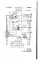
TELEFHONE SYSTEM Filed April 11, 1940 1o Sheets-Sheet 'r //v TERRUP m? 75 TRANS RELAYS a0 m/ws CONT/z 85 RING/N6 com/Emma FOR GENERATING FREQUENCIES FL 5 F2 RYIO R720 732 MORRIS E. GRIFFINS INVENTORS ,F' 7 sew E. PETERSON ATTORN EYS Oct. 14,
' lNTERRUP TER 75 S. E. PETERSON El At TELEPHONE SYSTEM 118d April 11, 1940 10 Sheets-Sheet 9 i MASTER 77MI/VGARELAYS 95 v 9Z4 I r6870 E Iv 1 v v R910 W p -9 4/ H 2900 I 92/ R950 902 r6873 92 5? [C874 wag H5930 I 1:1?940 x 6767 \F Qrv INVENTORS SETH E. PETERSON MORRIS E. GRIFFINS BY 9 E:
ATTORN EYS Patented Oct. 14, 1941 2.258.660 TELEPHONE SYSTEM Seth E. Peterson, Chicago, and Morris E. Griifins, Riverside, Ill., asslgnors to Associated Electric Laboratories, Inc., Chicago, 111., a corporation of Delaware Application April 11, 1940, Serial No. 329,087
53 Claims. (Cl. 179-27) The present invention relates to telephone systems, and more particularly to improvements in apparatus for providing call intercepting and supervisory services in conjunction with the use of the lines and automatic switching apparatus nected from the line, it is desirable to provide an arrangement whereby calls intended for the disconnected substation are routed to an operators position so that the calling subscribers may be informed that the called substation is no longer in service. Call intercepting service of this character is also desirable in other in-' stances when calls to substations actually in service are to be routed to an operators position.
It is an object of the present invention to provide improved apparatus of the character described, which is of simple and economical arrangement and which functions in a positive and reliable manner to intercept calls to one or more predetermined substations or lines of the system and automatically to route the intercepted calls to an operators position.
It is another object of the invention to provide improved apparatus of the character described, which is so arranged that the control of the call intercepting apparatus is effected through operation of a ringing interrupter which is common to all of the lines of the system.
It is a further object of the invention to provide improved apparatus of the character descrlbed,-which is so arranged that the operation thereof to intercept a call intended for a predetermined line or substation must be completed within a predetermined time interval after operation of the apparatus is initiated, and if not completed within this time interval the apparatus is automatically released.
It is still another object of the invention to provide improved call intercepting apparatus of the character described, which is arranged to intercept calls intended for substation designated by ringing currents of different codes and diiferent frequencies and wherein provisions are made for grouping the substations so thatthe substations arranged for call intercepting service and designated by ringing currents of the same frequency are served by apparatus controlled only by ringing currents of this frequency.
It is a. further object of the invention to proconnections between the lines.
vide an improved ringing interrupter which is of simple and economical arrangement and which operates in a positive and reliable manner to provide differently coded ringing voltages of different frequencies for use in the selective signalirig of called substations associated with the multiparty lines of a telephone system.
It is another object of the invention to provide an improved interrupter switch of the character described, which includes provisons for developing call intercepting impulses individual to the various coded ringing voltages of difierent frequencies in a predetermined timed relationship with these voltages, and which further includes apparatus for developing check pulses in timed relationship with the intercepting pulses for the purpose of controlling an associated call intercepting circuit to prevent the false operation and lockup of the circuit.
It is still another object of the invention to provide in an automatic telephone system including directively controlled switches for setting up connections between the lines of the system and apparatus for providing supervision of the switching equipment, an improved arrangement whereby on supervisory test calls the backbridge relays of the connector switches in use are prevented from operating.
The invention is illustrated in its embodiment in an automatic telephone system which comprises a plurality of subscribers lines, several of which are of the multiparty type, together with automatic switching equipment for setting up The system further comprises improved ringing apparatus of the coded ringing type for selectively signaling the substations associated with the multiparty lines of the system. More particularly, this apparatus includes two sources of ringing current of different frequencies and a ringing interrupter switch which functions to interrupt the voltages of the two sources to provide differently coded ringing voltages of the two frequencies. This .ringing interrupter includes a plurality of ringing leads, a plurality of call intercepting leads, a check pulse lead, and cyclically operative coding relays for impressing the differently coded ringing voltages upon the ringing leads during each cycle of operation thereof, and for impress-- me a predetermined potential upon the intercepting leads during predetermined intervals which individually-correspond to the different codes. The ringing interrupter iurther includes a circuit arrangement whereby check pulses are impressed upon the check pulse lead during the cycles of operation thereof, ringing voltage of 5 one frequency is coded and applied to the corresponding ringing leads, and during the intervening cycles of operation thereof ringing voltage of the other frequency is coded and applied to the remaining ringing leads.
The arrangement of .the system is such that the ringing voltages, intercepting pulses and check pulses developed through operation of the ringing interrupter, are utilized to control a pair of call intercepting circuits which respectively respond to ringing voltages of the two different frequencies to intercept predetermined calls routed to certain of the lines or substations of the system. The operation of each of these two circuits is under the joint control of'the ringing voltages applied to the associated lines arranged for call intercepting service and the application of the intercepting pulses to the intercepting leads, the arrangement being such that the application of an intercepting pulse to a predetermined one of the leads must partially overlap the application of ringing voltage to one of the lines arranged for intercepting service before operation of the intercepting circuit is initiated. After operation of an intercepting circuit is initiated, the circuit must complete its operation to intercept the call before a check pulse is impressed upon the check pulse lead. Otherwise, certain of the relays embodied in the intercepting circuit function to release the circuit. By virtue of this arrangement, the intercepting circuits are prevented from being inadvertently locked up due to faulty relay operation or transient voltages impressed upon the lines arranged for intercepting service.
Further features of the invention relate to the particular arrangement of the circuit elements whereby the above and additional operating features of the system are attained.
, The novel features believed to be characteristic of the invention are set forth with particularity in the appended claims. Theinvention, both as to its organization and method of operation, together with further objects and advantages thereof, will best be understood by reference to the specification taken in connection with the accompanying drawings in which Figs. 1 to .9, inclusive, taken together, illustrate an automatic telephone system having embodied therein the features of the invention briefly outlined above; Fig. graphically illustrates the mode of operation of the ringing-interrupter forming a part of the system illustrated; and Fig. 11 illustrates the manner of combining Figs. 1 to 9, inclusive, to obtain a unified system.
Referring to the drawings, the system there illustrated comprises an exchange at which are terminated a plurality of single party subscribers lines, one of which is indicated at it as extending to the substation A, and a plurality of multiparty subscribers lines, one of which is indicated at it as serving the substations B, C and D. For the purpose of setting up connections between the lines of the system automatic switching equipment is provided which includes line switches, a plurality of line switch-es, two of which are indicated at [5 and respectively, a plurality of selector switches including the switch 25, and a plurality of connector switches including the switch 30. The system further comprises a super.
visory operator's position 2! which may be provided in the exchange serving the above described single party and multiparty subscribers lines or in a distant exchange, as desired. This operators position terminates one end 'of a trunk which extends to an incoming selector switch 22 having access to the various connector switches of the system. The line switches I5 and 2G and the other similar switches'of the system are nonnumerical switches in the sense that they are inefiective to perform any line selecting function other than those of selecting idle ones of the selector switches. The selector and connector switches on-the other hand, are commonly known as numerical switches in that they are directive- 'ly controllable from the telephone stations of the system to perform particular line selecting functions. It will be understood that a plurality of switches of each type are provided in the system for performing the various line switching operations. Preferably, eachof the line switches 85, 20, etc., is of the well known rotary type of which there are several commercial embodiments. Each of the selector and connector switches is preferably of the well known Strowger type having embodied therein a wiper carriage structure adapted to be translated vertically to bring the wipers thereof to a position opposite to a particular level of bank contacts, and then rotated to bring the wipers into engagement with a particular set of contacts in a selected level; and control relays suitably connected and arranged to control the energization of the various magnets and the line switching in accordance with the particular function assigned to the switch. 0bviously, the particular arrangement of the control apparatus embodied in the switches of different type, is different in each instance, depending upon the character of the switch.
In order more clearly to explain the operation of certain of the circuits to which the present invention pertains, a portion of the relay equipment embodied in the connector switch 36 has been shown in detail. More particularly, this equipment comprises a slow-to-operate ringing control relay RI Ill, a slow-acting ring cut-pfi relay Rlllfi, a back-bridge or battery reversing relay R90, and a ringing code selecting switch I23. The switch I26 includes a wiper m arranged to traverse a set of associated contacts terminating ringing leads having differently coded ringing voltages impressed thereon.
In order to develop the difi'erently coded ringing voltages which are utilized in selectively signaling the subscribers served by'the multiparty subscribers lines, there is provided ringing apparatus which includes two sets of ringing converters diagrammatically illustrated at and an improved ringing interrupter 15. Each set of ringing generators comprises a pair of converters, preferably of the well known thump-start vibrating type, for developing ringing voltages having the frequencies F|- and F--2, respectively. In general, the arrangement of the ringing interrupter 15 is such that three differently coded. ringing voltages of each frequency F-i and F-Z are provided Briefly described, this interrupter comprises a group of ringing leads, ClEii to C1563, inclusive, which are labeled according to the frequency and code of the ringing voltages applied thereto; a check pulse lead; (2689; a group of call intercepting leads C151 to Cit-i2, inclusive, which are also labeled according supervisory leads including the leads C606, C140, C110 and C100; ,a pick-up pulse lead CH6: and a plurality of control relays for selectively controlling the application of diiferent voltages and potentials to the various enumerated leads. More specifically, the relay equipment of the interrupter 15 comprises a group of coding relays 60, a group of master timing relays 35, and a start relay R100. The coding relays are, when the start relay R100 is energized, operative in a cyclic manner under the control of the cyclic operation of the master timing relays 05, and function during alternate cycles of operation thereof, to
impress ringing voltage of the frequency F--l upon the three leads Cl, C153 and C155. At the end of these alternate cycles of operation of the coding relays 90, the ringing circuits are rearranged through operation of a set. of transfer relays 80 and a set of transfer control relays 85, so that during the intervening cycles of operation of the coding relays ringing voltage of the frequency F-2 is impressed upon the ringing leads C152, C154 and C156. The transfer and transfer control relays also function to control the intercepting pulse circuits so that intercepting pulses are impressed upon the 'F-l intercepting leads C151, C156 and C153 during alternate cycles of operation of the coding relays, and upon the F--2 intercepting leads C160, C15! and C162 during the intervening cycles of operation of these relays.
For the purpose of intercepting calls intended for predetermined lines or substations of the system, there are provided two call intercepting circuits, and 36, which are of identical arrangement and are associated with the lines arranged for intercepting service. These circuits function to route intercepted calls to an intercepting operators position over the trunks 33 and 31,
respectively. Briefly described, the call inter-,
cepting circuit 35 comprises a plurality of line connect relays, of which one relay, R2 I 0, is shown, which are individually associated with the lines arranged for call intercepting service. The circuit further comprises a plurality of code relays, R220, R230 and R240 which are common to the associated linesand in conjunction with the alternating current ring-up relays,.o'f which one relay, R200, is shown, function selectively to control the energization of the line connect relays. The common relay equipment of the call intercepting circuit 35 also includes a secondary ring up relay R320, a slow-acting ring cut-oil! relay R350, a back-bridge relay R330, a pair of control relays R300 and R310, and aslow-to-operate check pulse controlled relay R340. In the arrangement illustrated, the code relays R220, R230 and R240, are individually controlled over they leads C159, C158 and C151 by intercepting pulses corresponding to the coded ringing voltages having the frequency F-l and the codes I,
2 and 3, respectively. Accordingly, the circuit 35 is only utilized in intercepting calls to substations designated by ringing voltages having the frequency F-l. The call intercepting circuit 36, on the other hand, is arranged to intercept calls to predetermined substations designated by codedquency in this manner, a more simplified arrangement' is obtained which is considerably more reliable in operation.
The trunk circuit 4| terminating the trunk 31 is identical with the apparatus provided at the operator's position 40 to terminate the trunk 38 and is of substantially conventional arrangement.
Briefly described, this apparatus comprises an answer key 361 for connecting the operator's telephone set 310 to the trunk 39, a hold key 363, an incoming call signal lamp 366, and a ring-up relay R360 which is bridged across the conductors of the trunk 30 to respond to ringing current transmitted over this trunk and is arranged to control the energization of the signal lamp 366. An impedance element 362 is also provided which functions as a holding bridge across the conductors of the trunk 39 under the control of the hold key 363.
The common. equipment provided in conjunction with the automatic switching equipment described above, also includes test and supervisory apparatus for indicating the condition of the power and switching equipment and for enabling a spervisory, operator, such, for example, as an,
operator attending the position 2|, to obtain an indication of the condition of this equipment. In general, this supervisory and test apparatus is arranged to provide two classes of signals indicative of faults present in the power and switching equipment of the exchange. Thesesignalshave arbitrarily been designated as no-danger alarm signals and emergency alarm signals, a signal of the first type indicating that a fault is present in certain of the apparatus of the exchange which should be corrected but does not require immediate attention, and signals of the second type indicating that a fault is present in the apparatus of the exchange which is extremely serious and a hazard to continued operation of the system. The no-danger alarm signals are under the control of a group of relays 45 which include a nodanger fuse alarm relay R400 and three control relays, R410, R420 and R430. Similarly, the emergency alarm signals are controlled through the provision of a second group of relays 50, which'includes an emergency fuse alarm relay R440 and three control relays R450, R460 and R410. Access to the various alarm circuits controlled by the relays just described is obtained through the automatic switching equipment of the exchange, a group of supervisory test relays 60 being accessible to the connector switches of the system over the supervisory trunk l3. This group of supervisory test relays comprises a coding or pulsing relay R550, a pendulum type start relay R560, and a slow-to-operate relay R510 which is provided for the purpose of controlling the pulsing relay R550.
In order to control the condition of the various alarm circuits in accordance with the condition of the ringing apparatus briefly described above, there is provided a group of ringing apparatus test relays 65, which operate through a test cycle each time operation of the associated ringing apparatus is started, and function to set the emergency alarm relays 50 to indicate an emergency alarm condition in any case when the associated ringing equipment becomes faulty. Briefly described, this group of relays comprises an alternating current start relay R640, a pair of check pulse controlled relays R620 and R630, a timer control relay R600, and an alarm circuit control relay R6l0. In this regard it is pointed out that the alarm relays forming the two groups 40 and 50 are arranged to be controlled by a timer 55 which is of the all-relay type and comprises five relays R500, R510, R520, R530 and R540.
As indicated previously, the power and supervisory equipment includes duplicate sets of ringing generators and supervisory tone sources. Thus,,the ringing converter equipment 185 was described as including two sets of converters for developing ringing voltages having the frequencies F-l and F-2, respectively. Similarly, duplicate sets of dial and busy tone generators, respectively indicated at 000 and 005, are provided for developing the dial and busy tone currents. Provisions are made in the common equipment whereby the two sets of tone current sources and the two sets of ringing generators may selectively be conditioned for operation from the supervisory operator's position 21, for example, by the simple expedient of dialing different test numbers respectively designating the two sets of equipment; To this end there is provided a group of transfer relays 10, which comprises a transfer relay R680 and a pair of transfer control relays R010 and R000, the last of which is the slow-to-operate type. These relays not only enable a supervisory operator to condition either set of equipment for operation, but in addition rearrange the control circuits for the ringing'apparatus test relays 05 so that these relays will operate to perform their assigned test functions regardless of the set of ringing and tone equipment which is conditioned for use.
Operation of the ringing interrupter 75 In order to facilitate the explanation of the operation of the system as a whole the operation of the ringing interrupter 15 will first be considered. Operation of this apparatus is initiated in response to the appalication of ground potential to the start conductor C110, thereby to energize the start relay R100. It will be understood that this start lead is connected to groundin response to seizure of any one-of the final nu.- merical switches of the'system. When this lead is connected to ground a circuit extending by way of the choke coil 133 is completed for energizing the start relay R100. This relay in operating connects the F-1 ringing leads, C151, C153 and C155'to the ringing conductors C112, C110 and C114, respectively; and the F-2 ringing leads C152, C154 and C150 to the common ring cut-oil conductor C111. Thus, the F-1 ringing lead C151 is connected through the contacts 103 and 111' to the ringing conductor C112 when the start relay R100 operates. Similarly, the second F-! ringing lead C150 is connected through the contacts 105 and 110 to the second ringing conductor C113; and the third F-1 ringing lead C155 is connected through the contacts 101 and 115' to the third ringing conductor C110. The F-2 ring leads, C152, C100 and C150 are connected to the ring cut-off conductor C111 over obvious paths. This ring cut-ofi conductor may be connected directly to ground or to the negative ground. On the other hand, if the final selector switches of the system are arranged for battery imposed ringing, the X wiring shown in Fig. 1
of the drawings will be used whereby the ringing cut-on conductor C111 is connected to ground through the exchange battery.
The relay R100, upon operating also completes at its contact 102, a circuit for energizing the start relay R000, thereby to initiate a cycle of operation of the ringing apparatus test relay group 05 in the manner subsequently explained. At its contacts 100, the relay R100 prepares a circuit for transmitting pick-up pulses over the pick-up lead C115 to the ringing relays conventionally embodied in the final selector switches of the system. At its contact 101, the relay R100 completes an obvious path for grounding the release conductor C101, thereby to energize the relays R000 and R010. The circuit for energizing the relay R000 extends from ground by way of the contacts 101, C101, the winding of R800, the resistor 806, the contacts 822 and 803, C165, the contacts 102 and the resistor 108, to battery. The circuit for energizing the slow-to-operate relay R910 extends by way of the grounded conductor C161, the winding of R910 and the resistor 920, to battery. The relay R910 in operating opens at its contacts 911 the path normally short-circuiting the.slow-to-operate relay R920. At its contacts 912, the relay R910 prepares an operating circuit for the relays R810and R820.
The relay R000 in operating completes at its I contacts 805 a holding circuit for itself, this holding circuit extending by way of the grounded conductor C101, the winding of R000, the contacts 005, C108, the contacts 812, 033 and 852 in parallel, C109, and the resistor 148170 battery.- At its contacts 001 the relay R800 completes one of the multiple paths for short-circuiting the relay R020 thereby to prevent the latter relay from operating in response to operation of the relay R010. More specifically, this path extends short-circuiting the relay R130. At its contacts 803 the relay R000 completes a circuit for energizing the two relays R850 and R800 in series, this circuit extending by way of the grounded conductor C161, the winding of R050, the contacts 803 and the winding of R860 to battery.
At its contacts 000 the relay R000 completes a circuit for energizing the two relays R030 and R000 in series, this circuit extending by way of the grounded conductor C101, the winding of R830, the contacts 804, and the winding of R000 to battery. Thus, the relays R030, R800, R050 and R060 are all caused to operate in response to operation of the start relay R100. The relay R030 in operating, completes at its contacts 801, an obvious holding circuit for itself and the relay R000. At its contacts 802, the relay R000 completes the prepared series operating circuit for the relays R010 and R820, this circuit ex= tending by way of the grounded conductor C161, the winding of R810, C010, the contacts 012, C013, the contacts 032. and the winding of R020 to battery. At its contacts 833, the relay R030 opens one of the above-traced parallel holding circuits for the relay R800. The relay R800 in operating, completes at its contacts 851, an obvious holding.circuit for itself and the relay R000. At its contacts 052, the relay R050 opens a second of the multiple holding circuits for the relay R800.
The ringing relay R800, upon operating, opens at its contacts 801 a point in the common portion of the paths, traced hereinafter, for short-cir cuitingwhe relays" R010 and R000. At its contacts 002,- the relay R000 prepares a path for short-circuiting its associated control relay R050. At the remaining contacts controlled by the ringing'relay R050, certain additional circuit control operations are performed, which are described with particularity hereinafter. The ringing relay R040, upon operating, opens at its contacts 04!, a-.further point in the path for short-circuiting the relay Ri0 and prepares, at its contacts 042,
the path for short-circuiting the control relay R000. At its contacts 040, the relay R040 opens a point in the above traced operating circuit for the relay R000. At the'remaining contacts controlled by the relay R040, additional circuit control operations are performed which are described in detail hereinafter.
The relay R020, upon operating, further prepares, at its contacts 02!, the above-mentioned path for short-circuiting the relay R0l0 and opens, at its contacts 022, a further point in the operating circuit for the relay R000. At its contacts 020, the relay R020 prepares a circuit for energizing the relay R100. At its remaining con tacts the relay R020 performs additional circuit control operations described hereinafter.
Shortly following the operation of the relay R020, the slow-to-operate relay R0l0 operates to complete a locking circuit for itself and the relay R020, this locking circuit extending by way of, the grounded conductor 0151, the winding of R0! 0, the contacts 0! and the winding of R020 to battery. At its contacts 0!2, the relay ROI0 interrupts the holding circuit for the relay R000, causing the latter relay to release. At its contacts 005, the' relay R000 in releasing, opens a further point in its holding circuit. At its contacts 000 and 004, respectively, the relay'R000 opens the above-traced operating circuits for the relays R000, R040, R050 and R000. At its contacts 002 the relay R000 reprepares one of the operating circuits for the relay R040. At its contacts 00l the relay R000 interrupts the abovetraced path short-circuiting the winding of the relay R020. 7
The slow-to-operate relay R020 now operates to complete at its contacts 02!, an obvious circuit for energizing the slow-to-release relay R000. The relay R000, in operating, completes at its contacts 00!, an obvious path for short-circuiting the winding of the relay R0l0, causing the latter relay to restore. At its contacts 002, the relay R030 completes a circuit for energizing the relay R000, this circuit extending by way of the grounded conductor 0101, the contacts 002, 042 and 052, and the winding of R000 to battery.
The operation of the relay R000 marks the end tacts 022, 042, 052 and 002, the winding of R050, and the contacts 04! back to the grounded conductor C101. At its remaining contacts the relay R000 performscertain additional circuit control operations described hereinafter.
The relay R0|0 is deenergized and restores when its winding is short-circuited'by the relay R000. Upon restoring, the relay R0!0 recompletes the path for short-circuiting the winding of the relay R020, and at its contacts 0l2 opens the previously traced operating circuit for the relays R0l0 and R020. The relay R020 restores shortly following the release of the relay R0l0 and upon restoring, opens the operating circuit for the relay R000. The relay R000 in turn restores after an interval to interrupt, at its contacts 002, the above-traced path, short-circuiting the winding of the relay R050. As-a result, the two relays R000 and R050 are energized in series over a circuit extending by way of the grounded conductor C101, the contacts 04!, the winding of R050, the contacts 002 and the winding of R000 to battery. The completion of this circuit prevents the release of the relay R000 and results in operation of the relay R050. The relay R050 in operating, opens at its contacts 052, a further point in the operating circuit for the relay R000 and prepares a circuit for energizing the relay R040 at its contacts 05!.
The relay R000 in releasing, also opens the path short-circuiting the winding of the relay R0l0, whereby the latter relay is caused to re-- operate and open the path short-circuiting the winding of the relay R020. In reo'perating, the relay R0! 0 also completes the initiall traced circuit for energizing the relays R020 and R0l0 in series.- Shortly following operation of the relay of the first ringing period. This relay in operating, completes at its contacts 00!, a holding circuit for the relay R000 and'in so doing short-circuits the relay R050. This holding circuit extends by way of the grounded conductor C101, the contacts 00!, 0012, the contacts 052 'and the winding of R000 to battery. Obviously, with this circuit completed, both winding terminals of the relay R050 are groundedso that the relay R050 is short-circuited and restores. The relay R050 in restoring, opens the initially completed holding circuit for itself and the relay R000, and reprepares at its contacts 052, the holding circuit for the relay R000. The relay R000 in operating, also completes a path for short-circuiting the winding of the relay R050, this path extending by way of the grounded conductor C101, the con- R0l0, the relay R020 reoperates to recomplete the operating circuit for the relay R000. The last-mentioned relay in operating, again shortcircuits the winding of the relay R0!!! and com pletes the above-mentioned circuiting for energizing the relay R040. This circuit extends from ground by way of contacts 10!, 0101, the contacts 002, 042 and 05! and the winding of R040 to battery. When energized over this circuit the relay R040 operates to complete at the .X contacts 040, an obvious locking circuit for itself. After this locking circuit is completed the relay R040 opens its contacts 042 to interrupt its own operating circuit and the operating circuit for the relay R000. Atits contacts R0, the relay R040 interrupts the above-tracedseries holding circuit for the relay R000 and R050, causing both of these relays to restore. The relay R050 in restoring, opens at its contacts 05!, a further point in the operating circuit for the relay R040, and reprepares at its contacts 052, the previously traced operating circuit for the relay R000. The relay R000 in releasing, opens the above-traced holding circuit for the ringing relay R000. The ringing relay R000 now restores to open at its contacts 002 a further point in its own holding circuit, and further to prepare, at its contacts 05!, the holding circuit for the relay R040 and the path for short-circuiting the winding of the relay-R000.
The relay R0l0 in releasing, initiates the se-. quential release of the two relays R020 and R000 in the manner explained above. When the relay R000 restores, it again opens the path shortcircuiting the winding of the relay R0l0, and opens, at its contacts 002, the holding circuit for the relay R040. The relay R040 now restores to reprepare the series holding circuit for the two relays R900 and R990 and the operating circuit for the relay R900. From this point on the master timing relays 95 continue to interact, in the exact manner explained above, it being pointed out that the release of the relay R900 marks the end of the second ringing period. Thus, each operation of the relay R900 marks the end of an odd-numbered ringing period and each release of this relay marks the end of an even-numbered ringing period. At the beginning of the :fourth ringing period when the relay R900 reoperates, the above-mentioned holding circuit for the relay R940 is completed, this circuit extending by way of the grounded conductor C191, the contacts 90!, C912, the contacts 99! and 942, and the winding of R940 to battery. It will be observed that when this circuit is completed the upper and lower winding terminals of the relay R990 are both connected to ground, thus effectively short-circuiting this relay. As a result, the relay R990 is deenergized and restores to open at its contacts 93! the initially completed holding circuit for itself and the relay R940. At its contacts 932 the relay R930 opens the previously traced circuit for energizing the relays R9l0 and R920 in series. At its contacts 933, the relay R990 prepares a second of the three multiple branches of the holding circuit for the relay R800.
At the end of the fourth ringing period, the relay R900 is deenergized and restores in the manner explained above. This relay in releasing, opens at its contacts 90! the holding circuit for the relay R940. The relay R940 now restores to open, at its contacts 942, a further point in its holding circuit as traced above. At its contacts 94!, the relay R940 prepares a further point in one of the holding circuits for the relay R920. At its contacts 943, the relay 940 further prepares the previously traced operating circuit for the relay R900. At its contacts 943 the relay R940 also completes a circuit for energizing the relay R130. this circuit extending from ground by way of the contacts 10!, the winding of R130, the contacts 143. C199, the contacts 923 and 943, C195, the contacts 142 and the resistor 149 to battery.
At the end of the sixth ringing period as measured by the sixth cycle of operation of the mas- At its contacts 132, the relay R190, upon. oper- I ating, prepares another multiple branch in the holding circuit for the relay R900. At its contacts 13!, the relay R190 completes a holding circuit for itself, this holding circuit extending from ground by way or the contacts 10!, the winding of R130, the contacts 13!, C199, the contacts 902, C194, the contacts 145 and the resistor 149 to battery. It will be noted that the relay R140 is at this time shunted by the resistor 149. Accordingly, this relay does not operate at this time.
At the end of the fifth ringing period as measured by the fifth cycle of operation of the master timing relays 95, the relay R900 is again energized and operates to complete the abovementioned holding circuit for the relay R920, this circuit extending by way of the grounded conductor C191, thecontacts 90!, the conductor C912, the contacts 99!, 84! and 92!, and the winding of R920 to battery. It will be observed that when this circuit is completed, both winding terminals of the relay R9l0 are connected to ground and accordingly this relay is deepergized and restores. In releasing, the relay R9! 0 reprepares, at its contacts 9l2. another multiple branch in the holding circuit for the relay R900. At its contacts 9! the relay R9!!! opens a fil ter timing relays 95, the relay R990 is again deenergized and restores to openthe above-traced holding circuit" for the relay R920. When this circuit is opened, the relay R920 is deenergized and restores to open a further point in itsholding circuit. At its contacts 822, the relay R920 completes the previously traced operating circuit for the relay R900. At its contacts 823, the
relay R920 opens the previously traced operat-.
ing circuit for the relay R130.
The relay R900, in reoperating at the end of the sixth ringing period, again completes, at its contacts 90!, the previously traced pathfor short-circuiting the winding of the relay R920.
At its contacts 803 and 904, the relay R900.
recompletes the circuits for energizing the relays R890, R940, R950 and R990, causing all of these relaysto reoperate. At its contacts 905, the relay R900 recompletes the previously traced holding circuit for itself.
resistor 149 is connected in shunt with the winding of the relay R140, thus permitting the relay R140 to be energized in series with the relay R190 over a circuit which extends from ground by way of the contacts 10!, the winding of R190, the contacts 13! and the winding of R140 to battery. The current flow over this circuit is suflicient to hold the relay R130 operated, and to cause the operation of the relay R140. In operating. the relay R140 opens, at its contacts 149, one of the multiple holding circuits for therelay R900. At its contacts 14!, the relay R140 prepares a path for connecting the resistor 909 in shunt with the winding of the relay R130. At its contacts 142 and 143, the relay R140 opens a further point in the operating circuit for the relay R130. At its contacts 145, the relay R140 opens a further point in the path including the resistor 149 which normally shunts its own winding. At its contacts 144 the relay R140 further prepares the path for short-circuiting the winding of the relay R130. At its contacts 141, the relay R140 completes an obvious circuit for energizing the two transfer relays R1l0 and R120 in series.
sixth ringing period. At its contacts 122, the relay R120 in operating, disconnects the common ringing current conductor C110 from the F-! ringing converter output lead C150. At its contacts 12!, the relay R120 connects the common ringing current conductor C110 to the F2 ringing current lead C150 extending to the ringing converter having the output frequency F2. Thus, a change in the frequency of the ringing voltage impressed upon the conductors C112, C113 and C114 is effected. At its contacts 124, 129 and 128, the relay R disconnects the F! intercepting pulse leads C151, C159 and C159 from the intercept pulsing conductors C115, C119 and C111. At its contacts 123, .125 and 121, the relay R120 connects the F2 intercepting leads C190, C19! and C192 to the intercept pulsing conductors C115, C119 and C111, respectively. The transfer relay R1!0, upon operating, complates, at its contacts H2, H4 and 9, obvious paths for connecting the F-2 ringingleads C152, C154 and C159 to the ringing current conductors C112, C119 and C114 respectively, these leads being disconnected from the ring cut-01f for itself At its contacts 902, the relay R900 opens the circuit over which the Thus, the two transfer relays R'HO and R120 are caused to operate at the end of the conductor C11l at the contacts1l2', H4 and H8 when the relay R1l0 operates. At its contacts 1| l', "3 and H, the relay R1l0 disconnects the F-l ringing leads C151, C153 and C155 from the ringing current conductors C112, C113 and C114, respectively. Finally, at its contacts 1, H3 and "5, the relay R1I0 connects the F-l ringing leads Cl, C153 and C155 to the ring cut-off conductor 01.
The manner in which the coding relays 80 and the master timingrelays 85 operate during the seventh to twelfth ringing periods, is exactly the same as set forth above with reference to the operation of these relays during the first to sixth ringing periods, it being noted that during the seventh to twelfth ringing periods, ringing voltage of the frequency F--2 is coded through operation of the coding relays 80 in the manner more fully described hereinafter. At the end of the tenth ringing period, the relay R840 restores to complete an alternative holding circuit for the relay R140, this circuit extending from ground by way of the contacts "I and 1, C185, the contacts 843 and 823, C188, the contacts 144, C184, the contacts 802-, C163, and the. winding of R140 to battery. It will be noted that when this circuit is completed, both winding terminals of the relay R130 are connected to ground. Accordingly, the relay R130 is deenergized and restores. Upon restoring, the relay R130 opens, at its contacts 13i, a point in the initially completed holding circuit for itself and a point in-the circuit for energizing the relay R140. At its contact 132, the relay R130 opens a further point in one branch of the holding circuit for the relay R800. At the end of the twelfth ringing period the relay R820 restores in the manner pointed out above, to open, at its contacts 823, the above-traced alternative holding circuit for the relay R140. The relay R140. now restores to open, at its contacts 144, a further point in its holding circuit, and to recomplete, at its contacts 145, the path including the resistor 148 for short-circuiting its own winding. At its contacts 143, the relay R140 reprepares the operating circuit for the relay R130. At its contacts 14 I, the relay R140 opens a further point in the above-traced path for short-circuiting the winding of the relay R130. At its contacts 142, the relay R140 reprepares the operating circuit for the relay R800. Finally, at its contacts 141, the relay R140 interrupts the circuit for energizing the relays R1l0 and R120 in series. The relay R110 in releasing, again connects the F--I ringing leads C15l, C153 and C155 to the ringing current conductorsC112, C113 and C114, disconnects the F-2 ringing leads C152, C154 and C158 from the enumerated ringing current conductors, and connects the F-2 ringing'leads to the ring cut-oil conductor 01". The relay R120 in releasing, disconnects the common ringing current conductor C110 from the F-2' ringing converter lead C150, and reconnects this conductor to the F--l ringing converter lead C150. At its contacts 123 to 128, inclusive, the relay R120 disconnects the F2 intercepting leads C180, 018i and C182 from the intercept pulsing conductors C115, C118 and C111, respectively, and reconnects these conductors to the F--l intercepting leads C151 to C158, inclusive. From this point on the manner in which the master timing relays 85, the coding relays 80, the transfer control relays 85, and transfer relays 80 operate during succeeding ringing cycles, is exactly the same as described above.
The release of the interrupter 15 is under the control of the start relay R100. More particularly, when the start conductor CH4 is disconnected from ground, the 'relay R100 is'deenergized and restores to disconnect the release conductor C181 from ground. In response to this operation any operated ones of the relays R130, R140, R800, R8l0, R820, R830, R840, R850, R880, R800, R8 l0, R820, R840 and R850, are deenergized and restored. If the relays R1l0 and R120 are operated at the time the start relay R100 releases, these two transfer relays are deenerglzed and restore in response to the release of the relay R140. In the event the relay R830 is operated at the time the start relay R100 restores, this master timing relay is deenergized and restores in response to the release of the relay R820.
The ringing circuit control operations effected through operation of the relays embodied in the interrupter 15, in the manner explained above, will best be understood by reference to Fig. 10 of the drawings, wherein the sequence of relay operations and the various circuit control functions' effected thereby are plotted for one complete ringing cycle comprising twelve separate and distinct ringing periods. It will be observed from this chart that immediately the start relay R100 and the coding relay R850 operate, a ground pulse is impressed upon the pick-up lead CH5 over a path which extends from ground by way of the contacts 853, C118, the contacts 108 and the choke coil 135 to the pick-up lead CH5. As
' indicated by' the chart. the pick-up lead is disconnected from ground at the contacts 853 in response to the release of the relay R850,
:which, it will be recalled, occurs at the end of the first ringing period. From this chart it will also be observed that the pick-up lead Cl 55 is again connected to groundjn response to the operation of the relay R850 which occurs during the seventh ringing period and is disconnected from ground through the release of thisrelay at the end of this period.
Substantially concurrently with the application of ground potential to the pick-up lead Cl l5, the F-l, code i intercepting lead C151 and the frequency check lead C118, are connected to ground through operation of the relays R840,
R880 and R8l0, the path for grounding these leads extending by way of the contacts 8H and 823, the choke coil 8, the contacts'808, C880, and.the contacts 844'and 861, C115, and the contacts 124. As indicated by the chart, this path is broken at the contacts 823 during the first ringing period in response to the operation of the timing relay R820. Ground potential is also impressed'upon the Fl, code 2 intercepting lead C158 for a portion of the fifth ringing period. Thus, when the relay R820 releases during this period, a path is established which extends from ground by way of the contacts 833' and 823, the choke coil 8, the contacts 808, C880, the contacts 845, 0118, and the contacts 128 to the intercepting'lead C158. This path is momentarily broken when the relay R830 releases during the fifth ringing period to cause the energization and reoperation of the relay R8l0.
The relay R8i0 upon reoperating, however, completes an obvious alternative path for grounding the lead C158 at its contacts M3. The relay R8i0 in operating also opens the path shortcircuiting the relay R820, causing the latter relay to reoperate and break at its contacts 823, the alternative path over which the lead C158 is connected to ground. Thus, a ground pulse is transmitted over the F-l, code 2 intercepting lead C158 during the fifth ring ng Period. As indicated by the chart, the F-I, code 3 intercepting lead C189 is similarly connected to ground for a short time interval during the sixth ringing period. Thus, when the relays R9I 8 and R920 sequentially release during this period, a path is established which extends from ground by way of the operated contacts 833, the contacts 923, the choke coil 9", the contacts 801, C819, the contacts 848, C111, and the contacts 128 to the intercepting lead C189. This path is broken at the contacts 923 in response to the reoperation of the relay R920 which occurs shortly following the release of the relay R930. As explained previously, the transfer relay R120 is operated during the seventh to twelfth ringing periods. Accordingly, ground potential is impressed upon the F--2 intercepting leads C180, C18I and C182 forshortintervals during the seventh, eleventh and twelfth ringing periods, respectively, over paths which will be fully apparent in view of the foregoing explanation. It will be observed that the frequency check lead C180 is connected to the F--2, code I intercepting lead C180. Accordingly, ground potential is impressed upon this check lead, concurrently with the application of ground potential to the F-2, code I intercepting lead C180, for a short time interval during the seventh ringing period.
It will be observed from Fig. 10 of the drawings, that a ground pulse is impressed upon the pulse lead C889 during each cycle of operation of the master timing relays 95. The path over which this pulsing lead is grounded extends by way of the choke coil 888, C818, the contacts 922,
' of the second, ringing period in the manner preconductor C150, the contacts 122, C110, the conand the parallel connected contacts 9I3 and 933 g to ground. This path is obviously completedduring each interval when therelay R920 is concurrently operated with either or both of the two relays R9I0 and R930. It will be understood that the frequency of the pulses impressed upon the pulsing lead C888 depends upon the speed with which the master timing relays 95 sequentacts 8I3, C815, th contacts 908, C818, the contacts 888 and 824, C113, and the contacts H3 and 105 to the ringing le'ad C153. This circuit is interrupted at the contacts 908 when the relay R900 operates at the end of the third ringing period. The relay R900 upon operating at this time also completes, at the contacts 805, a path for connecting th ringing lead C158 to the ring cut-oil conductor 01", this path extending by way of the contacts 905, C818, the contacts 888 and 824, C113 and the contacts H3 and 105, to the lead C153. At the beginning of the fifth ringing period, when the relay R900 again restores, the F--I, code 2 ringing lead C153 is again connected to the F--I ringing converter over the above-traced circuit. Further, at the end of this ringing period, when the relay R900 reoperates, this circuit is broken at the contacts 808 and the lead C153 is again connected to the ring cut-off conductor C11I' through the contacts 908. The circuit for connecting the F-I ringing converter to the F-I, code 3 ringing lead C155 is completed when the relay R900 operates at the beginning-of the second ringing period, this circuit extending by way of the contially operate. In the preferred arrangement of 1 this interrupter, these timing relays are adjusted so that the pulses impressed upon the lead C889 occur at a rate of approximately 80 impulses per minute.
It will also be observed from the chart illustrated in Fig. 10 of the drawings, that the circuit connections extending between the ringing leads C15I to C158, inclusive, and the two converter leads C150 and C150 are so arranged that the voltage of the F-I ringing converter :is impressed upon the F-I, code I ringing lead C15I for the major portion of the first and second ringing intervals. The voltage of this same source is also impressed upon the F--I, code 2 ringing lead C153 throughout th third andflfth ringing periods. The F-I ringing current source is also connected to theF-I, code 3 ringing lead C155 during each of the second, fourth and sixth ringing periods. More specifically, the circuit for impressing the voltage of the ringing converter having the output frequency F-I upon the F-I, code I ringing lead C15l, is completed in response to operation of the relay R8l0, which occurs shortly following the operation oi the start relay R100. This circuit extends from the high'- potential terminal of the F-I ringing converter by way of C150, the contacts 122, G; the conductor C, the contacts 122, G110, the contacts 903, the conductor C811, the contacts 828, C114, and the contacts H5 and 101 to the ringing lead C155. This circuit is broken at the contacts 903 when the relay R900 restores at the end .of the second ringing period in the manner pre- -viously explained. The relay R900, in restoring, also completes, at its contacts 904, an obvious path for connecting the ringing lead C to the ring cut-01f conductor C11I. It will be observed that the circuit for connectingthis ringing lead to the F-I ringing converter does not extend through any of the contacts of the coding relays R830, R840, R850 and R860. Accordingly, the circuit is completed during each even-numbered ringing interval when the relays R820 and R900 are operated. Also, this ringing lead is connected to the ring cut-oil conductor C11I through the make contacts 828 of the relay R820 and the break contacts 904 of the relay R900 during each odd-numbered ringing period when the relay R900 is restored.
As explained previously, at the end of the sixth ringing period all of the coding relays RBI 0, R820, R830, R840, R850 and R880 are released. With these relays in their respective restored positions it will be observed that the three ringing current conductors C112, C113 and C114 are all connected to the ring cut-off conductor C11I through the back contacts of the coding relays R820 and R880. Thus, a ring cut-oif potential is impressed upon all of these conductors during all silent periods. From the foregoing explanation it will be recalled that the transfer relays 'R1I0 and R120 are caused to operate at the end of the sixth ringing interval and remain operated until the end of the twelfth ringing period. With these relays operated, the common ringing current conductor C110 is connected through the operated contacts 12! to the conductor C150 which extends to the high potential terminal of the F-2 ringing converter. Also, the F! ringing leads C15I, C153 and C155 are connected through the make contacts of the relays R100 and R1l0 to the ring cut-oil! conductor C11 I. C152, C154 and C156 are connected through the make contacts of the start relay R100 and the make contacts of the transfer relay R1! to the ringing current conductors C112, C113 and C114 respectively. It will be understood, therefore, that during the seventh to twelfth ringing D riods the voltage of the F2 ringing converter is impressed upon the ringing leads C152, C154 and C156 during intervals which respectively correspond to the intervals when the voltage of the F! ringing current source was impressed upon the ringing leads C15!, C153 and C155, respectively, during the first to sixth ringing periods. Thus, from Fig. 10 of the drawings it will be seen that the voltage of the F2 ringing converter is impressed upon the F-2, code ringing lead C152 for the major portion of the seventh and eighth ringing periods. Similarly, the voltage of this converter is impressed upon the F2, cod 2 ringing lead C154 for the duration of the ninth and eleventh ringing periods.
Finally, the voltage of this converter is impressed upon the F-2, code 3 ringing lead C156 for the duration of the eighth, tenth and twelfth ringing periods. The circuits over which the voltage of this converter is impressed upon the" Operation of the system Considering now the operation of the system as a whole, it may be assumed, for example, that a call intended for the substation B, associated with the line I I, is initiated at the telephone station A. When the call is initiated, a connection is extended to one of the selector switches of the system in response to operation of the line switch !5. More specifically, when the usual calling loop circuit is completed by way of the line !0, the line switch !5 operates to select a trunk line leading to an idle selector switch and to mark the calling line !0 as busy in the bank contacts of the connector switches having access thereto. Assuming, for example, that the selector switch 25 is selected by the line switch !5, when the trunk line leading to this selector switch is seized, the calling loop circuit is extended thereto and the selector switch is in condition to respond to the first 'series of impulses dialed at the calling substation. In response to the seizure of the selector switch 25, certain of the relays embodied therein operate in a well-known manner to impress ground potential upon the tone start lead CH6. This start'lead is normally connected through the break contacts 68! of the relay R660 to the the start conductor C692 extending to the No. 1 set of dial and busy tone generators 690. As a result, operation of the apparatus 690 is initiated. whereby the usual dial and busy tone sig- Further, the F--2 ringing leads switch 25 to the established loop circuit extendingbetween the calling station A and the selector switch whereby the usual dial tone signal is reproduced by the receiver provided at the calling telephone station.
When the first digit is dialed at the callingsubstation, the switch 25 elevates its wipers to a position opposite the level of bank contacts terminating the trunks leading to the connector switches having access to the desired line H. Following this operation and during the interdigit pause between the first and second digits, the wipers of the switch 25 are automatically stepped over the contacts of the selected level until a trunk line leading to an idle connector switch of the selected group is found. Assuming, for example, that the connector switch 30 is the first available idle connector switch in the selected group, when the wipers of the selector switch 25 are stepped into engagement-with the contacts terminating the trunk line extending to this connector switch, the subscribers loop circuit is extended to the switch 30. The connector switch is thus conditioned to respond to the second series of impulses dialed at the calling substation. During the operations just described, th dial tone lead C69! is disconnected from the loop circuit including the calling line !0 whereby the dial tone signal transmitted to the substation A is terminated. When the connector switch 30 is seized in the manner just described, certain of the control relays embodied therein, and more particularly the line and hold relays, operate to complete a path for impressing ground potential upon the ringing apparatus start conductor C! H, thereby to initiate operation of the ringing apparatus 185 and the ringing interrupter 15 in the event this apparatus is not already in operation. More specifically when the start lead CH4 is grounded, a circuit is completed for energizing the start relay embodied in the apparatus 185 and associated with the No. 1 set of ringing converters. To this end the conductor C! !4 is included in an obvious operating circuit for the relay R650. Upon operating, the relay R650 completes at its contacts 65! a circuit extending by way of the contacts 683 and the No. 1
startconductor C693 for energizing the start relay associated with the No. 1 set of ringing converters embodied in the apparatus 185. In operating, the relay R650 also performs additional circuit control operations referred to with particularity hereinafter.
In response to the dialing of the second digit at the calling telephone station A, the wipers of the connector switch 30 are stepped vertically to a position opposite the level of bank contacts at which are terminated the lines of the ten-line sub-group including the calling line H. Following this digit and during the inter-digit pause between the second and third digits, the connector switch 30 is conditioned to rotate its wipers step by step in accordance with the impulses of the controlled by certain of the relays in the selector When this third digit is dialed, the wipers of the switch 30 are operated into engagement with the set of bank contacts terminating the called line H. During the interdigit pause between the thirdand fourth digits, circuits are prepared for energizing the operating magnet of the frequency and code selecting switch !20 in accordance with the impulses of the fourth and final digit. This operating magnet responds to the impulses of the fourth digit by operating the wiper !2! into engagement with the contact of the associated contact set, which has impressed thereon ringing voltage of the particular frequency and code designating the called substation B. If it be assumed, for example, that the ringer. provided at the called substation B is constructed to respond only to ringing current of the frequency F-I and further, that the code designating the substation B is the code 2, th fourth digit dialedat the calling telephone station A will necessarily comprise three impulses so that at the conclusion thereof, the wiper I2 I will be left standing in engagement with th contact terminating the ringing leadC153. The frequency and code selecting switch I20 is provided with a release magnet, the operating circuit for which is prepared when the wiper I2I is stepped off normal.
In accordance with conventional practice, suitable provisions are made in the connector switch 30 for testing the selected line II to determine the idle or busy condition .thereof, for returning the usual busy tone signal over the establishedv loop circuit 'to the calling subscriber in the event the called line is busy, and for projecting ringing current of the selected frequency and code over the called line in the event this line is idle at the time it is selected. In this regard it will be understood that the busy tone current utilized.
to signal the calling party in th event the called line is found to be busy, is derived from the dial and busy tone generators 690 and is impressed on the calling loop circuit over the busy tone lead circuit is prepared through operation of certain 0696. Assuming that the called line is idle, a
of the relays embodied in the connector switch 30 for energizing the lower winding of the slowto-operate ringing control relay RI I0. This cir-' --cuit is thereafter completed at the beginning of the next cycle of operation of thecoding relays 90 embodied in the ringing interrupter 15 when ground potential is impressed upon the pick-up lead CH5. More, specifically, when the relay R850 operates, following operation of the con- I nector switch 30 to select the line II, the ringing relay RI I0 is energized over a circuit which extends from ground by way of the contacts 853, C118, the contacts 109, the choke coil 135, the pick-up lead CH5, certain of the contacts embodied in th relays of the connector switch 30, the private conductor I I0 of the selected line and through the winding of the cut-off relay conventionally embodied in the line switch 20 to battery. When this circuit is completed the cut-off relay embodied in the line switch.20 partially operates to disconnect the windings of the line relay embodied in this line switch from the conductors of the called line I I, thereby to clear this line of the shunt impedance represented by the line relay windings. Completion of the circuit just traced also results in the energization and operation of the ringing control relay RI I0. This relay, upon operating completes, at the X contacts I I2, a prepared holding circuit for itself, this holding circuit having previously been prepared through operation of certain of the other relays embodied in the connector switch 30. The relay RI I0 in operating, also completes a prepared path for impressing ground potential upon the private conductor I la of the called line, thereby to mark this line as busy in the bank contacts of the other connector switches having access thereto. At its contacts III and H3, the relay RI I0 completes a circuit for transmitting ringing current of the selected frequency and code over the conductors of the line II. In th present assumed case, the circuit traversed by the ringing current across the conductors of the line II, the con-- ductor Ila, the contacts III and IN, the upper winding of the ring cut-off relay RI00, and the exchange battery to the grounded terminal of the ringing converter in use. It will be understood that in this case, since the ringing voltage is superimposed upon ground, the Y wiring illustrated in Fig. '1 is used in the ringing interrupter 15. Portions of the ringing current transmitted over the line II are obviously shunted through the ringers respectively provided at the other substations associated with the line III All such ringers, which are tuned to respond to the frequency F- I, operate. Due to the coded character of the ringing voltageimpressed upon the ringing lead-C153, however, the subscriber at the substation B is signaled that the call is intended for his substation, and the other subscribers served by the line and having ringers which respond to ringing current of the frequency F I are informed that th call is not intended for their sub-stations. A portion of the ringing current is also shunted in the usual manner over the calling loop circuit to energize the receiver provided at the calling substation, thereby to indicate to the calling subscriber that the called substation is being signaled. It will be'apparent from the foregoing explanation that the code of the ringing current projected over thelin II is such that swered at the called substation B. More particularly, when the receiver at this substation is removed from its supporting hook or cradle, a direct current conductive bridge is connected across the conductors Na and Nb of the line II to complete a circuit for energizing the upper Winding for the slow-acting ring cut-oil relay RI00. This circuit may be traced as extending from ground by way of the ring cut-off conductor C11l, certain of the back contacts of the coding relays or the relay R300, the conductor C113, the contacts 1 I3 and 105, the ringing lead C153, the wiper I2I, the contacts and H3, the conductor IIb, the. bridge across the conductors ofthe line II, the conductor Ila, the contacts III and IBI, and the upper winding of RI00 to battery. When its upper winding is energized over this circuit, the relay RI00 operates to close its X contacts I03, thereby to complete a prepared holding circuit for itself. Thereafter, the relay RI00, at its contacts-WI and I05, opens two points in its operating circuit and two points in the above-traced circuit for projecting ringing current over the line It. At its contacts I02 and I04, the relay RI00 completes the desired conversational circuit between the calling substation A and the called substation B. When the relay RI00 operates it also functions to open the
Priority Applications (1)
| Application Number | Priority Date | Filing Date | Title |
|---|---|---|---|
| US329087A US2258660A (en) | 1940-04-11 | 1940-04-11 | Telephone system |
Applications Claiming Priority (1)
| Application Number | Priority Date | Filing Date | Title |
|---|---|---|---|
| US329087A US2258660A (en) | 1940-04-11 | 1940-04-11 | Telephone system |
Publications (1)
| Publication Number | Publication Date |
|---|---|
| US2258660A true US2258660A (en) | 1941-10-14 |
Family
ID=23283783
Family Applications (1)
| Application Number | Title | Priority Date | Filing Date |
|---|---|---|---|
| US329087A Expired - Lifetime US2258660A (en) | 1940-04-11 | 1940-04-11 | Telephone system |
Country Status (1)
| Country | Link |
|---|---|
| US (1) | US2258660A (en) |
Cited By (1)
| Publication number | Priority date | Publication date | Assignee | Title |
|---|---|---|---|---|
| US2542749A (en) * | 1947-10-22 | 1951-02-20 | Stromberg Carlson Co | Telephone intercept system |
-
1940
- 1940-04-11 US US329087A patent/US2258660A/en not_active Expired - Lifetime
Cited By (1)
| Publication number | Priority date | Publication date | Assignee | Title |
|---|---|---|---|---|
| US2542749A (en) * | 1947-10-22 | 1951-02-20 | Stromberg Carlson Co | Telephone intercept system |
Similar Documents
| Publication | Publication Date | Title |
|---|---|---|
| US2410520A (en) | Telephone system | |
| US2183649A (en) | Automatic telephone system | |
| US2592784A (en) | Restricted service telephone system | |
| US2335481A (en) | Telephone system | |
| USRE23056E (en) | Relay automatic telephone system | |
| US2258660A (en) | Telephone system | |
| US2214213A (en) | Telephone system | |
| US2031692A (en) | Telephone system | |
| US2195317A (en) | Telephone system | |
| US3033932A (en) | Selective ringing multi-party telephone system | |
| US2333038A (en) | Telephone system | |
| US1910972A (en) | Telephone system | |
| US2224497A (en) | Telephone system | |
| US2177069A (en) | Telephone system | |
| US2252309A (en) | Telephone system | |
| US2427000A (en) | Coin-operated telephone system | |
| US2131568A (en) | Telephone system | |
| US2274759A (en) | Telephone system | |
| US2285282A (en) | Telephone system | |
| US2286431A (en) | Telephone system | |
| US2706747A (en) | Selector repeater for telephone systems | |
| US2218850A (en) | Telephone system | |
| US2733295A (en) | lomax | |
| US2322650A (en) | Impulsing apparatus for signaling systems | |
| US2524131A (en) | Automatic telephone system incorporating mixed service connectors |