US2251908A - Heel grading machine - Google Patents
Heel grading machine Download PDFInfo
- Publication number
- US2251908A US2251908A US222678A US22267838A US2251908A US 2251908 A US2251908 A US 2251908A US 222678 A US222678 A US 222678A US 22267838 A US22267838 A US 22267838A US 2251908 A US2251908 A US 2251908A
- Authority
- US
- United States
- Prior art keywords
- carrier
- heels
- heel
- saw
- work
- Prior art date
- Legal status (The legal status is an assumption and is not a legal conclusion. Google has not performed a legal analysis and makes no representation as to the accuracy of the status listed.)
- Expired - Lifetime
Links
Images


Classifications
-
- B—PERFORMING OPERATIONS; TRANSPORTING
- B27—WORKING OR PRESERVING WOOD OR SIMILAR MATERIAL; NAILING OR STAPLING MACHINES IN GENERAL
- B27M—WORKING OF WOOD NOT PROVIDED FOR IN SUBCLASSES B27B - B27L; MANUFACTURE OF SPECIFIC WOODEN ARTICLES
- B27M3/00—Manufacture or reconditioning of specific semi-finished or finished articles
- B27M3/20—Manufacture or reconditioning of specific semi-finished or finished articles of lasts; of shoes, e.g. sabots; of parts of shoes, e.g. heels
Definitions
- This invention relates to shoe heel grading machines.
- a workholder of this type can be driven at a constant speed to grip the successive heels placed thereon and to move them past a stationary revolving saw. Since the heels can be presented to the saw with little or no gap between successive heels so that the saw cuts almost continuously instead of intermittently (as in the hand machine, the saw rotating idly after each heel is graded while the work carrier is moved back to loading position and is reloaded), the heels.
- 'I'he sections of the Work-holder are mounted on a plurality of articulated blocks adapted to engage and be driven by corresponding flats on a powerdriven driving Wheel, mated ,with an idler Wheel of similar shape, these wheels being mounted at opposite ends of a horizontal table having guideways thereon so that the articulated Work-holder travels along the top of the table in a straight line during which travel the heels are placed in the holder by the operator and are automatically graded.
- the work holder includes also a continuous sectional breast or lip stop and a continuous sectional clamp jaw, sections of each of which are carried by the platform sections.
- the jaw closes on the heels as they approach the grading saw and grips them by their seat end portions between the clamp jaw and the breast stop, pressing the heels tightly against the top surface of the platform.
- the jaws automatically open to permit them to fall by gravity into a container as the carrier turns down over the driving Wheel. Both the closing and opening movements of the jaws are automatic and each heel is individually clamped, regardless of whether the heels are loaded on the carrier close together or spaced widely and irregularly apart as might be done by an operator While learning.
- any heel grading machine namely, the work-holder and the saw.
- a single adjustment made without tools, serves to adapt the work-holder to any type or size of Louis or Cuban heel.
- r-he saw requires two adjustments regularly, and occasionally a third adjustment. rIhe regular adjustments are for heel height and heel wedge and the occasional one is an adjustment crosswise of the work-holder path and in the plane of thesaw lblade to compensate for saw wear or to changethe angle of the tangent of the initial saw Ycontact -on the lheel relative vto the workholder path.
- a novel combination -of adjusting devices is provided which is specifically designed for the most convenient and rapid handling of the necessary settings for the saw on an automatic grading machine.
- the details of the construction used will be more clearlyl shown and described in the drawings and accompanying description, but broadly it-censists of'a vertical support, perpendicular to the work-holder path, on which is 5 mounted av 4pivoted plate for heel wedge, pivoting about Van imaginary axis positioned at the front-edge ⁇ of the toplift surface of an average heel, another plate arranged for sliding adjustment on the pivoted plate for the above-mentionedoccasional adjustment, and a third plate slidable on the second for Vthe heel height adjustment.
- the height of a heel is measured in inches and fractions thereof in a line perpendicular to the graded surface. I have arranged the direction of height adjustment so that a standard scale maybe attached for record purposes and will read directly. .That is, a 1/8 inch adjustment of the saw'as shown on the .scale will result in a 1/8Y inch change in the heel height as understood and Yused bythe trade. 1
- Thewedge of the heel is commonly defined as the angle of inclination between the plane of the heel seat and that of the toplift surface and is usually expressed in degrees.
- -an easy-reading degree scale facilitates quickland accurate setting for the heel wedge. Both height and wedge readings may be readily recorded for future set-ups.
- the occasional third adjustment needs no recording because ithas no Veffect on the height or wedge of the heel.
- two bolts are provided which lockrall three adjustments simultaneously and all adjustments are hand-crank operated.
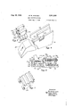
- Figure 2 is an end view of the same, on a larger scale.
- Figure 3 is a partial plan View showing the work holder.
- Figure 4 is an isometric showing of details of the carrier block supporting ways at the driving sprocket end.
- Figure 5 is an isometric view of the bottom of one of the carrier blocks.
- Figure 6 is an enlarged View of one of the cushioned clamping pressure levers and associated apparatus clamping a heel.
- Figure 7 is an isometric view of the top of one lof Vthe carrier blocks.
- Figure 8 is a fragmentary plan View of a grading saw cutting through a heel.
- rllhe grading vmachine illustrated on the drawings comprises a frame I0 which supports a table I2.
- a tool support which consists of a number of relatively adjustable members including a vertical plate Id supported by a pair of legs I5 which are secured to the sides of the table by bolts I6.
- a pivoted plate I8 mounted on the tool support is a pivoted plate I8, guided for pivoted movement about a horizontal axis by a circular track Zi] and actuated by a worm 22 rotatable by a hand crank or wheel 23 carried by a' bracket 24 made fast to the plate I4 by bolts 26.
- the center of pivotal adjustment of the plate .i8 is preferably located at the front edge of the toplift endof a heel of average height in position to be graded.
- Gear teeth 28 are cut in the arcuate edge of the pivoted plate I8 to engage Athe worm 22.
- Degree markings 30 on the plate 'i3 and an index mark 32 on the vplate I4 provide means for recording settings of the plate I3.
- a plate 34 is mounted against the pivoted plate I8 and is adjustable approximately horizontally with reference thereto, being guided by a slightly inclined track or spline 35.
- a plate 36 is mounted against the plate 34 and is adjustable u-p an-d down, being guided by a track or spline 3l which is perpendicular to the track 35.
- an electric motor t Secured -to the plate 36 by bolts 38 is an electric motor t having a shaft 42 on which is mounted a circular saw it which is a grading tool.
- the motor is arranged so thatthe axis of its shaft is parallel to the spline 37 and the plane of the saw liliV is parallel to the spline 35.
- the saw may lbe adjusted axially by moving the plate 36 on the plate 34, or edgewise in its own plane by moving the plate 36 ⁇ on the plate I8.
- a scale 46 and indexy d'8 are provided to indicate axial adjustments, the scale being preferably graduated to read in '116ths of an inch.
- the plates 3e, 3d, L8 Vand I4. are normally locked together by a pair of Vstuds .59 which extend through slots 5,2 inthe plate 34, rectangular openings 54 in the plate
- the slots 52 and openings 54 and 56 are so shaped, asindicated in Figure 2, that the studs 50 will not interfere with the adjustment of the respectivev plates.
- the threaded ends of the studs 50 which project beyond the cap-plate 58 are supplied with nuts-S0 which are set lup to lock the plates in adjusted position.
- nuts-S0 which are set lup to lock the plates in adjusted position.
- a compression spring 62 and a spacing collar 84 are loosely mounted on each stud between the cap-plate 58 and the nut Gil.
- suitable slow-motion devices are provided. These comprise the worm 22 carried by the plate I4 and meshing with a worm gear sector 28 on the plate I8, a rotatable screw 66 carried by a bracket 68 on the plate I8 and threaded into the edge of the plate 36, and a screw I rotatably mounted on a bracket 'i2 on the plate 34 and screw-threaded into the edge of the plate 36.
- the screws 66 and l0 are provided respectively with operating means such as hand cranks '14 and T6.
- any desired adjustment of the grading saw is quickly made by loosening the nuts 60, operating the crank 23 to adjust the inclination of the saw axis for the desired wedge angle, operating the crank '16 for axial adjustment of the saw according to the desired height of the heel, and, if desired, operating the crank 14 to shift the saw in its own plane for more favorable engagement with the heels to -be graded.
- a geared-head motor S bolted to a cross member 82 on the frame I, drives a sprocket wheel 84 mounted for rotation in suitable bearings il on the frame I El and connected to the motor by a chain gli.
- a mating idle sprocket wheel S4 is mounted in a similar manner to the opposite end of the frame IIJ, these two sprocket wheels acting to drive and partially support an endless articulated sectional carrier
- 00 is guided and supported along the top of the table I2 for straight line travel in Ways including a pair of rails
- the carrier comprises a series of blocks
- the blocks have spaced longitudinal bearing surfaces along both sides and portions of the bottom to match corresponding surfaces on ways H32 and
- a central roller IEB within the channel which serves as a bearing member for the block as it approaches one end of the rails
- the rollers ride on short auxiliary rails
- the purpose of this construction is to prevent any part of any block from rising above the level of the line-up of the blocks in the ways along the table top.
- a roller IESA has almost reached the highest point to which the sprocket wheel 94 can carry it, that is, on the level with the rollers of the blocks along the table top.
- the roller IBSA rolls onto the center support I Il) which will then support the front end of the block following the roller IBSA until the next following roller IUBB has been raised by the sprocket wheel 94 to the table level, at which time said ⁇ block will have ybeen swung about the roller IilBA into horizontal alinement with its predecessors along the table top, whereupon it is in proper alinement to ride upon the tracks
- the parts are similar, but their arrangement and the resulting action differ somewhat from those at the oncoming end of the table due to the fact that the carrier is pulled along the table top by the powerdriven sprocket wheel lili.
- the sprocket wheel rlil is on a level with the idle sprocket wheel 94, but it is somewhat more remote from the end of the ways
- 080 has recently rolled off the end of the center support H2 and is supported only by the tension on the adjacent blocks set up by the driving sprocket wheel 8f3.
- il2 terminate at the point where the center support begins, considered in the direction of carrier travel. So, there being no block bottomy support for the block between the rollers W8C and IIlBD, said block is free to swing about the axis of the roller IUSD to aline itself with the tensional pull thereon by the driving sprocket wheel 84 without any portion of the block being levered up above the level of the following blocks.
- the top faces of the blocks in the upper stretch of the carrier form in effect a continuous supporting surface for the work, extending longitudinally of the blocks.
- this supporting surface moves successively through a loading zone in Which heels are placed thereon, an operating zone in which the heels are graded by the saw 44, and a discharge zone in which the graded heels are discharged from the carrier.
- the work-supporting surface which is substantially continuous through the loading, operating and discharge zones are sectional work-gripping elements
- Heels to be graded may be placed at random at any point on this surface in the loading zone. Hence no regular spacing between successive heels is required.
- 20 is provided to protect the operator from injury from the closing gaps between the blocks as they come up around the idle sprocket wheel 94, and a loading platform
- the Yadjustable supporting plates for the grading nsaw are located yabove the carrier a-suicient ydistance to be clear of the path of heels'moving Vwith the carrier from th loading station to the saw.
- 00 is equipped with a fixed heel lip -or ⁇ breast 'stop segment 430 carry-ing a resilient strip
- 30 'in the blocks in the yupper stretch oi Athe 'carrier are alinedand forma substantially continuous breast stop-or abutment memberagainstwhich the work may press.
- 46 and acts toclose the movable gripping elements such asjaw segments
- the movable gripping elements such asjaw segments
- the resultant spring pressure causes the movable jaw segments to clamp the heels lirmly by the ⁇ seat end portion only thereof While they are being graded bythe saw '44, the position of which is indicated in Figure 3 by the outline of its cutting edge
- 80 preferably faced with 'a resilient material, such as rubber, acts to keep 75 ⁇ the graded heel lightly clamped, after Aleaving the cutting area, until entirely clear ofthe saw.
- 96 is arranged at an angle to theY direction of progress of the blocks
- 14 is lockable in its adjusted position by suitable clamping bolts extending through slots
- 06 is connected to the frame
- 93 and .index may be provided to identify :i5
- the heels to be graded are of a 'regular style similar -to heels previously graded' on the machine
- the proper kind of grading cut is illustrated in Figure 8.
- the actual chip 2l2 is a Wedgeshaped piece if the heel blank has been correctly out to minimize waste of material. Having secured the proper grade in height and wedge, records of these settings together with the workholder setting may be made on suitable cards for future set-ups of the same style without experiment.
- the motors 40 and 8U are started, whereupon heels may be loaded onto the work carrier with random spacing between successive heels as shown in Figure 3, it being necessary only t0 see that the toplift end of the heel is uppermost and that the breast of the heel is squarely against the breast stop
- the heels are carried along by the carrier
- the arrangement of the various adjustments is such as to provide maximum economy of time required for accurate adjustment.
- the adjustment of the saw blade in its own plane can be made at any time without affecting the location of the cuts on heels.
- No scale is used here as the setting is not critical and is infrequently made.
- its object is to compensate for reduction in saw diameter as a result of wear or to cause the teeth of the saw to cut across the heel top at some preferred angle, such as shown in Figure 8, in which tle teeth out across the top at an angle of about 45 to the direction of movement of the heel.
- the three regularly used adjustments are all fitted'with scales, and their direction and manner of adjustment are specially designed for best results on this particular machine and purpose.
- the pivotal movement pivots around an imaginary axis positioned relative to an average heel so that a minimum effect on the height of the heel will result from an angular change.
- a tool In a wood heel making machine, a tool, an endless carrier movable past said tool, means on said carrier for ciamping thereon heels placed thereon with random spacing for passage past said tool, means for automatically moving successive portions of said clamping means into clamping position as they approach said tool, and means for automatically moving said portions to releasing position as they recede from said tool.
- a machine of the class described comprising a stationary tool, an endless work carrier having Ull a stretch extending past said tool on which work may be carried, means for driving said carrier, and means on said carrier for clamping the work placed on said carrier at any random points along the portion of said stretch approaching said tool.
- a stationary tool an endless work carrier movable past said tool, clamping means carried by said carrier for gripping work placed on said carrier at Aany random points along the portion of said carrier approaching said tool, and means for automatically operating said clamping means to grip the work on the carrier as it reaches a certain point in its approach to the tool and as it passes the tool and tc release the work after it has passed the tool.
- a heel grading machine comprising a staisty saw, an endless work carrier movable past said saw, clamping means on said carrier for gripping heels placed with random spacing along the portion of said carrier approaching the saw, means for driving said carrier, and means for automatically operating said clamping means to grip heels on the carrier when they reach a certain point in their approach to said saw and to release heels on the carrier after they have passed the saw.
- a tool an endless carrier having a straight stretch adjacent to said tool, said carrier comprising a series of dat-topped blocksforming a substantially continuous surface in said straight stretch, means on said carrier for clamping heels placed at any point on a substantial portion of said carrier approaching said tool, means for automatically operating said clamping means to grip the heels placed thereon as they pass the tool and to release the heels thereafter.
- an endless work carrier including a series of blocks linked together, said carrier having a straight stretch wherein the blocks form a substantially continuous work-supporting surface, clamping means on said blocks for gripping work placed at random on said surface, said clamping means including alined stationary elements forming a substantially continuous abutment and elements movable toward said abutment to grip the work, and means for automatically actuating said movable elements 'to grip and release work on said surface as it passes predetermined points.
- an endless work carrier including a series oi blocks linked together, a pair of spaced wheels about which saidcarrier passes, a horizontal supporting member for said carrier between said wheels, and means including auxiliary supports at the ends of said supporting member for causing said lblocks to move onto and oii vfrom said supporting member without projecting above the level of the blocks upon said supporting member.
- an endless carrier including a series of blocks linked together at their ends, each block having on its bottom a pair of spaced longitudinal bearing surfaces with a channel between and a bearing element at each end of each block within said channel, and means for supporting a stretch of said carrier, said means including trackways to receive the said bearing surfaces of successive blocks and auxiliary ways extending approximateiy a blocks length beyond 'the ends of said trackways to receive said bearing elements.
- an endless work carrier comprising a series of blocks linked together, a pair of spaced wheelsfor driving and partially supporting said carrier, a table supporting the upper stretch of said carrier betweensaid wheels, clamping mechanism including alined stop elements secured to said blocks and forming a substantially continuous abutment member on said upper stretch'of the carrier and a plurality of gripping elements on each block movable crosswise of the block to grip heels placed at random at any point along the top of the block, a cam member engageable by successive gripping elements to move said elements into engagement with heels on the blocks, springloaded pressing elements engageable by said gripping elements to press said elements firmly against said heels, and means for retracting said gripping elements after they have passed the pressing elements to release the heels gripped thereby.
- an endless work carrier comprising a series of blocks linked together, a pair of spaced wheels for driving and partially supportingy said carrier, a table supportingl the upper stretch of said carrier between said wheels, clamping mechanism including alined stop elements secured to said blocks and forming a substantially continuous abutment member on said upper stretch of the carrier and a plurality of ⁇ gripping elements on each block movable crosswise of the block to grip heels placed at random at any point along the top of theblock, aA cam member engageable by successive gripping elements to move said elements into engagement with heels on the blocks, springloaded pressing elements engageable by said gripping elements to presss said elements iirmly against saidr heels, means for retracting said gripping elements, and means for simultaneously adjusting said cam member, pressing elements and retracting means as a unit for operation on heels of a different size.
- an endless work carrier In a heel grading machine, an endless work carrier, a grading. saw mounted adjacent to said' carrier, a supporting plate for said saw, means for adjusting said saw in the direction off' its; axis relatively to said plate, means for adjustably turning said plate in its own plane to changethe angle in inclination of said axis, meansr for adjusting said' saw edgewise in its own plane without disturbing any other adjustments thereof, and means for securing said saw and plate, in adjusted position.v
- a grading saw In a heel grading machine, a grading saw, supporting means therefor including a series of relatively movable members, means -for releasably'securing said members together, and slowmotion means for causing adjusting movements between said members when released to move the saw in. its own plane without disturbing any' other adjustments of said. saw, to move the sawy in the direction of, its aXis, and to change the angle of inclination of said axis.
- adjustable means for supporting said tool comprising a xed plate, a plurality of plates in successive face to face engagement on one side of said xed plate, each of said plurality of plates being adjustable in its own plane relatively to said xed plate, a cap plate on the other side of said fixed' plate, a pair of bolts, passing through all of said plates, securing means on'said bolt for clamping said plates tightly together, and springs on said bolts for maintaining frictional engagement between said plates when the securing means are released.
- adjustable means for supporting said saw comprising a iixed vertical-plate, a series of three plates in successive face tok face eng-agement on one. side of said fixed plate, said three plates being respectively adjustable in their own planes relatively to the iixedr plate in a direction parallel to the axis of said saw, in a direction parallel to the plane of ksaid saw, and angularly about an axis approximately in the plane of the saw, a cap plate on the other side of said fixed plate, and means for clamping all of said plates tightly thereon.
- a stationary tool an endless Work carrier movable past said tool, clamping means on said carrier for gripping a succession of similar objects placed with random spacing along the portion of the carrier approaching the tool, means for driving the carrier, and means for automatically operating said clamping means to grip said ob jects on the carrier when they reach a certain point in their approach to the tooland to release said objects on the carrier after they have passed the tool.
- an endless work carrier comprising a series of blocks linked together, a pair ofspaced wheels for driving and partially supporting said carrier, a table supporting the upper stretch of said carrier between said wheels, clamping mechanism including alined stop elements secured to said' blocks and forming a substantially continuous abutment member on said upper stretch of the carrier and a plurality of gripping elements on each block movable crosswise of the block to grip heels placed at random at any point along the top of the block, a cam member engageable by successive gripping elements to move said elements into engagement with heels on the blocks, spring-loaded pressing elements engageable by said gripping elements to press said elements firmly against said heels, and means for simultaneously adjusting said cam member and press-y ing elements as a unit for operation on heels of a different size.
- a heel grading machine comprising a stationary saw, an endless work carrier movable past said saw, clamping means on said carrier for gripping the seat end portions only of heels placed close together along the portion ofthe carrier approaching the saw, and means for automatically operating said clamping means to grip heels on the carrier when they reach a certain point in vtheir approach to the saw and to release heels on the carrier which have passed the saw.
- a heel grading machine comprising a tool. an endless flexible carrier movable past said tool, means on said carrier for gripping closely spaced heels thereon by their seat end portion only when approaching said tool and releasing said heels after they have passed the tool, and means for operating said gripping means at predetermined points in their travel.
- a heel grading machine comprising a tool, an endless carrier having a straight stretch adjacent to said tool, said carrier comprising av series of flat-topped blocks forming a substantially continuous surface in said straight stretch said machine having loading and discharge stations on opposite sides of said tool, means on said carrier for gripping by the seat end portion only heels placed close together on said carrier at said loading station, and means for operating said gripping means at a predetermined point as they approach said tool 21.
- a heel grading machine comprising a stationary rotatable tool, a flexible endless conveyor having a portion adapted to carry heels past said tool in operative relation thereto, means for gripping the heels by the seat end portion only, said means including clamping elements on said conveyor having relative movements toward and away from each other in a direction transverse with respect to the direction of travel thereof with the conveyor, and means for actuating said clamping elements to clamping position as they reach a predetermined point in their approach to the tool.
- a heel grading machine comprising a rotatable tool, an endless articulated sectional carrier adapted to carry heels past said tool in operative relation thereto, means for gripping the heels by the seat end portion only on said carrier as they approach said tool, said gripping means comprising elements having gripping and releasing movements relative to each other in a direction transverse with respect to the direction of travel of the adjacent portion of the carrier, and means for moving said elements to gripping relation when they reach a predetermined point in their approach to the tool.
- a stationary tool In a machine of the class described, a stationary tool, an endless Work carrier movable past said tool, clamping means carried by said carrier for gripping work placed on said carrier at any random points along the portion of said Icarrier approaching said tool, and means automatically operating said clamping means to grip the work on the carrier as it reaches a certain point in its approach to the tool and as it passes the tool.
- a heel grading machine comprising a stationary saw, an endless Work carrier movable past said saw, clamping means for gripping by their seat end portions heels placed with random spacing along the portion of said carriage approaching the saw, means for driving the carrier, and means for automatically operating said clamping means to grip the heels on the carrier When they reach a certain point in their approach to the saw.
- an endless work carrier including a series of blocks linked together, a pair of spaced Wheels about which said carrier passes, a horizontal supporting member for said carrier between the Wheels, and means including an auxiliary support at an end of said supporting member for causing said blocks as they pass said end of the supporting member to do so Without projecting above the level of the blocks on the supporting member.
- an endless Work carrier including a series of blocks linked together, a pair of spaced wheels about which said carrier passes, a horizontal supporting member for said carrier between the Wheels, and means including an auxiliary support at the discharge end of said supporting member for causing said blocks as they pass from the supporting member to the wheel at the discharge end of the supporting member to do so Without projecting above the level of the blocks on the supporting member,
- means for conveying the work from a loading zone through an operating Zone said means including Worksupporting and work-gripping elements which are substantially continuous through said zones, and means for causing said Work-gripping elements to converge to grip the work when passing 'from the loading zone to the operating Zone.
- means for conveying the work from a loading zone through an operating zone said meansl including Work-supporting and work-gripping elements which are substantially continuous through said zones, means for causing said work-gripping elements to converge to grip the work when passing from the loading zone to the operating zone, and preloaded spring means opposing divergence of said Work-gripping means within the operating zone.
Description
Aug. 12, 1941. M. w. HOWARD I HEEL GRADING MACHINE 'Filed Aug. 2),; 193s 4 Sheets-Sheet 1 y rw w ma 4 Sheets-Sheet 2 Aug. 12, 1941. M. w. HOWARD HEEL GRADING MACHINE Filed Aug. 2', 1958 Z4 ZZ Aug. 12, 1941. M. w. HOWARD 2,251,908
HEEL GRADING MACHINE v l Filed Aug. 2, 1958 4 Sheets-Sheet 3 MevTmMowm' NAW, Gm, Qu 'v www Aug. 12,r 1941. M. w, HOWARD 25251903 HEEL GRADING MACHINE Filed Aug. 2, 1958 4 Sheets-Sheet 4 [Mentor Mex''mn N Howm Patented Aug. 12, 1941 HEEL GRADING MACHINE Merton W. Howard, Haverhill, Mass., assignor to Pope Machinery Corporation, Haverhill, Mass., a corporation of Massachusetts Application August 2, 1938, Serial No. 222,578
30 Claims.
This invention relates to shoe heel grading machines.
In the manufacture of wood heels, the grooving and turning operations are performed while the seat and toplift end surfaces are in their original parallel planes, as in the blank. Usually the next operation consists of sawing off the toplift end of the turned heel at an angle relative to the seat surface, ranging ordinarily from to in order that the heel may have the proper wedge to cause it to tread correctly on the nnished shoe. This sawing operation is called grading in the trade and has heretofore been done on a simple hand machine consisting of a circular saw rotatable on a horizontal aXis and a work carrier on an arm swingable on a parallel axis to bring the work against the edge of the saw. The usual motions of placing the lWork on the carrier and feeding it to the saw render both the operator and the work liable to injury since the fingers of the operator often move near to the saw edge and the rate of progress of the saw through the work is governed largely by the arbitrary feeding pressure exerted on the work by the operator. Excessive pressure is liable to make the saw chip the work as it emerges in completing the cut, thus spoiling the heel.
It is an object of the present invention to provide an automatic machine for grading heels in a much more rapid and efficient manner and with greatly lessened danger of injury to the operators hands.
Continuous straight-line heel movement past the saw is arranged to avoid idle movement of the work-holders. the production only by the operators skill and speed, a work-holder has been devised :which will accept and hold heels Wherever and whenever the operator feeds them in, within the limits of a generous loading area, it being required only that the breast of the heel be positioned against a member which is in effect a continuous unbroken breast gauge or stop. Thus heels may be placed on the carrier in mutual Contact or with random spacing between them.
A workholder of this type can be driven at a constant speed to grip the successive heels placed thereon and to move them past a stationary revolving saw. Since the heels can be presented to the saw with little or no gap between successive heels so that the saw cuts almost continuously instead of intermittently (as in the hand machine, the saw rotating idly after each heel is graded while the work carrier is moved back to loading position and is reloaded), the heels.
With the object of limiting may be moved past the saw at a speed Well under the maximum for proper cutting but fast enough to keep ahead of the operator loading heels thereon.
It is a further object of the invention to provide a Work-holder which includes a substantially continuous platform of abutting sections carried by an endless carrier which passes around spaced wheels, the platform sections being so supported that no portion of any section will rise above the plane of the platform at any time in the operation of the work-holder. 'I'he sections of the Work-holder are mounted on a plurality of articulated blocks adapted to engage and be driven by corresponding flats on a powerdriven driving Wheel, mated ,with an idler Wheel of similar shape, these wheels being mounted at opposite ends of a horizontal table having guideways thereon so that the articulated Work-holder travels along the top of the table in a straight line during which travel the heels are placed in the holder by the operator and are automatically graded.
The work holder includes also a continuous sectional breast or lip stop and a continuous sectional clamp jaw, sections of each of which are carried by the platform sections. The jaw closes on the heels as they approach the grading saw and grips them by their seat end portions between the clamp jaw and the breast stop, pressing the heels tightly against the top surface of the platform. When the heels have been graded, the jaws automatically open to permit them to fall by gravity into a container as the carrier turns down over the driving Wheel. Both the closing and opening movements of the jaws are automatic and each heel is individually clamped, regardless of whether the heels are loaded on the carrier close together or spaced widely and irregularly apart as might be done by an operator While learning. By driving the Work-holder only just'fast enough so that the fastest operator is not quite able to load the heels in actual contact with each other, a cutting speed past the saw is had that is substantially slower than the average used by the old hand operators. This moderate cutting speed, which is about 15 feet per minute, results in improved sawed surfaces and less edge fracture on the heels While still providing opportunity for any operator to place heels on the platform as rapidly as he can handle them.
It is a further object of the invention to p-rovide a grading machine which insures maximum safety to the operator. This is accomplished by providing loading space at a point remote from the saw and by suitable saw guards made possible by the structure of the machine.
The number and facility of adjustments constitute a major consideration in any extremely high production machine of the type illustrated. If l0 minutes are required to set over a machine when 5 minutes would have served, with better and/or fewer adjustments, a substantial difference of production per day or week results.
Essentially there are only two elements to be adjusted in any heel grading machine, namely, the work-holder and the saw. In the machine hereinafter described, a single adjustment, made without tools, serves to adapt the work-holder to any type or size of Louis or Cuban heel. r-he saw requires two adjustments regularly, and occasionally a third adjustment. rIhe regular adjustments are for heel height and heel wedge and the occasional one is an adjustment crosswise of the work-holder path and in the plane of thesaw lblade to compensate for saw wear or to changethe angle of the tangent of the initial saw Ycontact -on the lheel relative vto the workholder path.
Y .According `to the vpresentv invention, a novel combination -of adjusting devices is provided which is specifically designed for the most convenient and rapid handling of the necessary settings for the saw on an automatic grading machine. The details of the construction used will be more clearlyl shown and described in the drawings and accompanying description, but broadly it-censists of'a vertical support, perpendicular to the work-holder path, on which is 5 mounted av 4pivoted plate for heel wedge, pivoting about Van imaginary axis positioned at the front-edge `of the toplift surface of an average heel, another plate arranged for sliding adjustment on the pivoted plate for the above-mentionedoccasional adjustment, and a third plate slidable on the second for Vthe heel height adjustment.
The height of a heel is measured in inches and fractions thereof in a line perpendicular to the graded surface. I have arranged the direction of height adjustment so that a standard scale maybe attached for record purposes and will read directly. .That is, a 1/8 inch adjustment of the saw'as shown on the .scale will result in a 1/8Y inch change in the heel height as understood and Yused bythe trade. 1
Thewedge of the heel is commonly defined as the angle of inclination between the plane of the heel seat and that of the toplift surface and is usually expressed in degrees. For this adjustment -an easy-reading degree scale facilitates quickland accurate setting for the heel wedge. Both height and wedge readings may be readily recorded for future set-ups. The occasional third adjustment needs no recording because ithas no Veffect on the height or wedge of the heel. For extreme facility, two bolts are provided which lockrall three adjustments simultaneously and all adjustments are hand-crank operated. Y,By slightly loosening the two bolts, any .adjustment can be made a matter of seconds and the-parts relocked These and other features of the invention will be more clearly understood from the following description ofV a .preferred embodiment Aof the invention shown in the drawings in which- Figur-e1 is a front elevation of a machine embedyingl 4the invention. j
Figure 2 is an end view of the same, on a larger scale.
Figure 3 is a partial plan View showing the work holder.
Figure 4 is an isometric showing of details of the carrier block supporting ways at the driving sprocket end.
Figure 5 is an isometric view of the bottom of one of the carrier blocks.
Figure 6 is an enlarged View of one of the cushioned clamping pressure levers and associated apparatus clamping a heel.
Figure 7 is an isometric view of the top of one lof Vthe carrier blocks.
Figure 8 is a fragmentary plan View of a grading saw cutting through a heel.
rllhe grading vmachine illustrated on the drawings comprises a frame I0 which supports a table I2. Above the table is a tool support which consists of a number of relatively adjustable members including a vertical plate Id supported by a pair of legs I5 which are secured to the sides of the table by bolts I6. Mounted on the tool support is a pivoted plate I8, guided for pivoted movement about a horizontal axis by a circular track Zi] and actuated by a worm 22 rotatable by a hand crank or wheel 23 carried by a' bracket 24 made fast to the plate I4 by bolts 26. The center of pivotal adjustment of the plate .i8 is preferably located at the front edge of the toplift endof a heel of average height in position to be graded. Gear teeth 28 are cut in the arcuate edge of the pivoted plate I8 to engage Athe worm 22. Degree markings 30 on the plate 'i3 and an index mark 32 on the vplate I4 provide means for recording settings of the plate I3. A plate 34 is mounted against the pivoted plate I8 and is adjustable approximately horizontally with reference thereto, being guided by a slightly inclined track or spline 35. A plate 36 is mounted against the plate 34 and is adjustable u-p an-d down, being guided by a track or spline 3l which is perpendicular to the track 35. Secured -to the plate 36 by bolts 38 is an electric motor t having a shaft 42 on which is mounted a circular saw it which is a grading tool.. The motor is arranged so thatthe axis of its shaft is parallel to the spline 37 and the plane of the saw liliV is parallel to the spline 35. Thus the saw may lbe adjusted axially by moving the plate 36 on the plate 34, or edgewise in its own plane by moving the plate 36 `on the plate I8. For recording particular settings, a scale 46 and indexy d'8 are provided to indicate axial adjustments, the scale being preferably graduated to read in '116ths of an inch.
Asindicated in .Figures 1 and 2, the plates 3e, 3d, L8 Vand I4. are normally locked together by a pair of Vstuds .59 which extend through slots 5,2 inthe plate 34, rectangular openings 54 in the plate |28, arcuate openings 56 in the plate I4, and' nally through holes in the cap-plate 58 which bears against the face of the plate I4 opposite to the plate I8 and bridges the openings in the plate I4. It will be noted that the slots 52 and openings 54 and 56 are so shaped, asindicated in Figure 2, that the studs 50 will not interfere with the adjustment of the respectivev plates.
The threaded ends of the studs 50 which project beyond the cap-plate 58 are supplied with nuts-S0 which are set lup to lock the plates in adjusted position. As it is desirable to have a frictionaly drag between the plates when released, a compression spring 62 and a spacing collar 84 are loosely mounted on each stud between the cap-plate 58 and the nut Gil. Y
For controlling the adjustments of the plates, suitable slow-motion devices are provided. These comprise the worm 22 carried by the plate I4 and meshing with a worm gear sector 28 on the plate I8, a rotatable screw 66 carried by a bracket 68 on the plate I8 and threaded into the edge of the plate 36, and a screw I rotatably mounted on a bracket 'i2 on the plate 34 and screw-threaded into the edge of the plate 36. The screws 66 and l0 are provided respectively with operating means such as hand cranks '14 and T6. Thus any desired adjustment of the grading saw is quickly made by loosening the nuts 60, operating the crank 23 to adjust the inclination of the saw axis for the desired wedge angle, operating the crank '16 for axial adjustment of the saw according to the desired height of the heel, and, if desired, operating the crank 14 to shift the saw in its own plane for more favorable engagement with the heels to -be graded.
A geared-head motor S, bolted to a cross member 82 on the frame I, drives a sprocket wheel 84 mounted for rotation in suitable bearings il on the frame I El and connected to the motor by a chain gli. A mating idle sprocket wheel S4 is mounted in a similar manner to the opposite end of the frame IIJ, these two sprocket wheels acting to drive and partially support an endless articulated sectional carrier |00.
The upper stretch of the carrier |00 is guided and supported along the top of the table I2 for straight line travel in Ways including a pair of rails |02 and lateral guides |63. As illustrated in the drawings, these supporting rails are shown in a horizontal position, but it is to be understood that this term is used for convenient description and not by way of limitation as the machine shown could obviously be operated in a tilted position. The carrier comprises a series of blocks |94 which are linked together by hinge pins i and abut one another in the upper stretch. The blocks have spaced longitudinal bearing surfaces along both sides and portions of the bottom to match corresponding surfaces on ways H32 and |03, the bottom -being hollow to form a central channel between the bearing surfaces, as shown in Figure 5. On each of the pins |06 is a central roller IEB within the channel which serves as a bearing member for the block as it approaches one end of the rails |02 and as it leaves the other end of the rails. The rollers ride on short auxiliary rails ||0 and |I2 which are located midway between the rails |92 but extend a blocks length beyond the ends of these rails, the central rail Il being at the oncoming end of the ways and the rail I|2 being at the offgoing end. The purpose of this construction is to prevent any part of any block from rising above the level of the line-up of the blocks in the ways along the table top. Ordinarily, when an elongated body is pulled up over the edge of a horizontal supporting surface and onto the surface by a tensional drag, the leading end will be pulledup above the surface until the body rocks on the edge as a fulcrurn, raising the following end of the body and lowering the leading end until they are at the same level upon the surface. Thus the leading end rises momentarily above its ultimate level. To avoid this undesirable result, the supporting means for the carrier blocks moving onto the table are arranged tol support the leading end only until the following end has been elevated to the same level. Thus the block swings about its leading end instead of some intermediate point. The action of the carrier supporting means on approaching blocks can be seen in Figure 1, in which the carrier runs from right to left along the table top. A roller IESA has almost reached the highest point to which the sprocket wheel 94 can carry it, that is, on the level with the rollers of the blocks along the table top. At this point the roller IBSA rolls onto the center support I Il) which will then support the front end of the block following the roller IBSA until the next following roller IUBB has been raised by the sprocket wheel 94 to the table level, at which time said `block will have ybeen swung about the roller IilBA into horizontal alinement with its predecessors along the table top, whereupon it is in proper alinement to ride upon the tracks |82 without any portion thereof having risen above the level of the block tops on the table.
On the off-going end of the table the parts are similar, but their arrangement and the resulting action differ somewhat from those at the oncoming end of the table due to the fact that the carrier is pulled along the table top by the powerdriven sprocket wheel lili. The sprocket wheel rlil is on a level with the idle sprocket wheel 94, but it is somewhat more remote from the end of the ways |62 so as to prevent severe downward pressure on the center support ||2 at certain stages in the rotation of the driving sprocket wheel Sil. As seen in Figure 1, the roller |080 has recently rolled off the end of the center support H2 and is supported only by the tension on the adjacent blocks set up by the driving sprocket wheel 8f3. The rails |il2 terminate at the point where the center support begins, considered in the direction of carrier travel. So, there being no block bottomy support for the block between the rollers W8C and IIlBD, said block is free to swing about the axis of the roller IUSD to aline itself with the tensional pull thereon by the driving sprocket wheel 84 without any portion of the block being levered up above the level of the following blocks.
The top faces of the blocks in the upper stretch of the carrier form in effect a continuous supporting surface for the work, extending longitudinally of the blocks. During the operation of the machine, this supporting surface moves successively through a loading zone in Which heels are placed thereon, an operating zone in which the heels are graded by the saw 44, and a discharge zone in which the graded heels are discharged from the carrier. With the work-supporting surface which is substantially continuous through the loading, operating and discharge zones are sectional work-gripping elements |30 and |49 which are also substantially continuous through these zones and which are caused to converge to grip Vthe heels on the carrier when passing from the loading zone to the operating zone, and to diverge to release the graded heels after passing through the operating zone. Heels to be graded may be placed at random at any point on this surface in the loading zone. Hence no regular spacing between successive heels is required.
A safety guard |20 is provided to protect the operator from injury from the closing gaps between the blocks as they come up around the idle sprocket wheel 94, and a loading platform |22 is mounted in fronti of theloading portion -ofthe carrier-to protect the operator and to assistfh-im in loading heels onto the -work carrier at the loading station adjacent to the Vplatform vl2f2. rThe upper stretch of -thec-arrier-extends past Vthe plates which support the grading-saw -as well -as past the saw-itself. The useof the arcuate track 2-0 to Fguide the angular adjustive movements of the plate --|'8 on the 'plate |4 vobviates -the need of a-'pi-votal-connection between the plates at the axis of such-adjustive movements. Hence, as shown in Figure '2, the Yadjustable supporting plates for the grading nsaw are located yabove the carrier a-suicient ydistance to be clear of the path of heels'moving Vwith the carrier from th loading station to the saw.
Each Yblock |04 in the endless carrier-'|00 is equipped with a fixed heel lip -or `breast 'stop segment 430 carry-ing a resilient strip |32 Aof rubber en -the like -to `prevent damage to the heels |34, andl a plurality `of movable gripping elements such as jaw segments |40 each also carrying a resilient .strip |42. The *stopV segments '|30 'in the blocks in the yupper stretch oi Athe 'carrier are alinedand forma substantially continuous breast stop-or abutment memberagainstwhich the work may press. -Each jaw segment |40 'is mounted for-sliding motion vcrosswise of the block on a slidebar |44guided closely within slideways '|45 withinthe block and Abelow its top surface. 'Each jaw segment |40 is -counterboredfor a roller |46 mounted Afor rotation on aV vshoulder screw |48. A- pre-clamping cam Ibar |50 `faced with resilient material -is-engaged 4by successive lrollers |46 and acts=toclose the movable gripping elements such asjaw segments |40 intoV Contact With heels |34 loaded properly oriented, that is, withV 'their *breastsy (in-the case 'of vCuban heels) or their lips (in the -case of Louis heels) squarely against the lip -or breast stop |30, onto the carrier at the carrier at the loadingstation as'the carrier moves constantly -to theleft as lseen in Figure 3. The
spacing between successive heels 'is entirely arbit-ra-ry'as the heeis are `placed 'at any point whatever on the portion of the carrier passing the loading station, the only requirement being that they be inverted and properly oriented. As the heels move along from the loading station, they are rst `lightly clamped by the pre-clamping bar |150. The movable jaw rollers |46 are then carried past a series of cushioned pressure levers |60 pivoted on a common shaft |62. Compression springs |64 'are supported by bolts '|65 and are pre-loaded kby nuts |66 to produce a predetermined cushioned pressure against the .pressure levers |00V to hold them against bolt heads |68 until moved slightly away from said bolt heads by jaw segments which are in engagement with heels on the carrier, as shown in Figure 6. The resultant spring pressure causes the movable jaw segments to clamp the heels lirmly by the `seat end portion only thereof While they are being graded bythe saw '44, the position of which is indicated in Figure 3 by the outline of its cutting edge |10. This leaves the toplift end portion of the heels free and clear, as shown in Figure 6, for `unobstructed operation thereon by the grading saw 44.
The bolts |65 which carry the pressure springs |64 are threaded into a clamp frame |14 and locked in adjusted position by lock nuts |16. A post-clamping bar |80, preferably faced with 'a resilient material, such as rubber, acts to keep 75` the graded heel lightly clamped, after Aleaving the cutting area, until entirely clear ofthe saw.
A cam bar 19t-is provided t'o open the heel clamps :after they `have moved past the bar to release the heels for free discharge from the carrier. The Abar |96 is arranged at an angle to theY direction of progress of the blocks |04 and isengaged 4by the ends of successive slide bars '|44'ito push the jaw segments |40 back from the lip or :breast stop |30 after the clamps have left the grading area. Since the spacing and relationships between the bars |50, |780 and |96 should be maintained constant, these bars are connectedtogether so that all of them move as a unit when adjustments are being made.` To this end 'the pre-clamping, clamping, post-clamping and clamp-opening mechanisms are all carried by the clamp frame |14 as a unit and are adjustable therewith transversely of the work carrier Lon-the table lI2 under guidance of a key |82 by means of `a screw |84 collared in the table |2 yagainst axial movement. The screw |84 is threaded through a boss |06 which projects down through the table l2 from the clamp frame |14 and -is actuable by a handle |88. The clamp frame |14 is lockable in its adjusted position by suitable clamping bolts extending through slots |9| in the frame |14 and threaded into the table :|2.y These bolts may be operated by any convenient means .such as hand-wheels |92. The cam bar |06 is connected to the frame |14 by a link |98,..one end of which is secured to a boss 200 projecting down from the frame. A suitable q scale |93 and .index may be provided to identify :i5
any particular adjustment of the frame |14, so that, when the frame has once been properly adjusted -for vgrading a certain style and size of heel, a record can be made Aof the scale reading so that theV frame can later be quickly and accurately reset .if another lot of heels of the same style andsize are to .be graded.
In operation, if the heels to be graded are of a 'regular style similar -to heels previously graded' on the machine, the single work-holder adjustment and the two active saw adjustments `are set by record, using the scales |93, 46 and 30, and the machine vis ready to operate. If a new style is to'be. grad'edfa heel is placed in the work holder between the breast stop |30 and one of the jaw segments 2|'40 which is inline with a pressure lever |60. y'The frame :|14 vis then moved forward by manipulation of the crank |88 until said pres sure flever is rocked slightly away from contact with the corresponding bolt head |68, as shown in Figure 6, so that this jaw segment is acted upon fby theiforce of the spring |64. The carrier is then :ready to clamp heels properly for grading.V 'Thewedge angle lof the heel, which will be :either from the work tag or from a sample graded heel, vwill-be set in degrees according to scale. 30.,.1but the height must be secured by experimentlfeither by moving a sample graded heel, if atphand, 'under the saw 60 and then adjusting said'saw v-by manipulation of the handle 16 to bring 'the saw just -into contactwith the top of the sample Iheel, or, if a certain height is specined ibut no sample lis available, the saw is setv high, an experimental cut made, and then a correct height adjustment made by the aid of scale 46, the divisions o'f which are spaced apart by l-Gthsofan inch, the customary unit for measuring heelhe'ights, and -correspond to 16ths of an inch :diierences in v`the actual heights Aof theY graded heels. Heel heights are measured on per.
pendiculars to the toplift face of the graded heel, this face being produced by the grading saw. It is for this reason that the saw is adjusted in the direction of its axis for diierent heel heights.
The proper kind of grading cut is illustrated in Figure 8. The actual chip 2l2 is a Wedgeshaped piece if the heel blank has been correctly out to minimize waste of material. Having secured the proper grade in height and wedge, records of these settings together with the workholder setting may be made on suitable cards for future set-ups of the same style without experiment. When adjustments have been made for the grading of a batch of heels, the motors 40 and 8U are started, whereupon heels may be loaded onto the work carrier with random spacing between successive heels as shown in Figure 3, it being necessary only t0 see that the toplift end of the heel is uppermost and that the breast of the heel is squarely against the breast stop |30. The heels are carried along by the carrier |00 and are automatically graded by the saw 44, after which the movable clamping jaw will be automatically opened by the cam ISB and the graded heels discharged by gravity as the endless carrier turns downward over the driving sprocket wheel 84 at the left side of the machine as seen in Figure 1.
The arrangement of the various adjustments is such as to provide maximum economy of time required for accurate adjustment. The adjustment of the saw blade in its own plane can be made at any time without affecting the location of the cuts on heels. No scale is used here as the setting is not critical and is infrequently made. When it is made, its object is to compensate for reduction in saw diameter as a result of wear or to cause the teeth of the saw to cut across the heel top at some preferred angle, such as shown in Figure 8, in which tle teeth out across the top at an angle of about 45 to the direction of movement of the heel. The three regularly used adjustments, however, are all fitted'with scales, and their direction and manner of adjustment are specially designed for best results on this particular machine and purpose. The pivotal movement pivots around an imaginary axis positioned relative to an average heel so that a minimum effect on the height of the heel will result from an angular change.
It is evident that various modifications and changes may be made in the particular form of invention herein shown and described without departing from the spirit and scope of the invention as deiined in the following claims.
I claim:
l. In a Wood heel making machine, a tool, an endless carrier movable past said tool, said machine having a loading station on one side of said .y
tool and a discharge station on the other, and means carried by said carrier for clamping thereon heels placed thereon at any point along the portion thereof passing the loading station.
2. In a wood heel making machine, a tool, an endless carrier movable past said tool, means on said carrier for ciamping thereon heels placed thereon with random spacing for passage past said tool, means for automatically moving successive portions of said clamping means into clamping position as they approach said tool, and means for automatically moving said portions to releasing position as they recede from said tool.
3. A machine of the class described, comprising a stationary tool, an endless work carrier having Ull a stretch extending past said tool on which work may be carried, means for driving said carrier, and means on said carrier for clamping the work placed on said carrier at any random points along the portion of said stretch approaching said tool.
4. In a machine of the class described, a stationary tool, an endless work carrier movable past said tool, clamping means carried by said carrier for gripping work placed on said carrier at Aany random points along the portion of said carrier approaching said tool, and means for automatically operating said clamping means to grip the work on the carrier as it reaches a certain point in its approach to the tool and as it passes the tool and tc release the work after it has passed the tool.
5. A heel grading machine comprising a staionary saw, an endless work carrier movable past said saw, clamping means on said carrier for gripping heels placed with random spacing along the portion of said carrier approaching the saw, means for driving said carrier, and means for automatically operating said clamping means to grip heels on the carrier when they reach a certain point in their approach to said saw and to release heels on the carrier after they have passed the saw.
6. In a wood heel making machine, a tool, an endless carrier having a straight stretch adjacent to said tool, said carrier comprising a series of dat-topped blocksforming a substantially continuous surface in said straight stretch, means on said carrier for clamping heels placed at any point on a substantial portion of said carrier approaching said tool, means for automatically operating said clamping means to grip the heels placed thereon as they pass the tool and to release the heels thereafter.
7. In a machine of the class described, an endless work carrier including a series of blocks linked together, said carrier having a straight stretch wherein the blocks form a substantially continuous work-supporting surface, clamping means on said blocks for gripping work placed at random on said surface, said clamping means including alined stationary elements forming a substantially continuous abutment and elements movable toward said abutment to grip the work, and means for automatically actuating said movable elements 'to grip and release work on said surface as it passes predetermined points.
8. In a machine of the class described, an endless work carrier including a series oi blocks linked together, a pair of spaced wheels about which saidcarrier passes, a horizontal supporting member for said carrier between said wheels, and means including auxiliary supports at the ends of said supporting member for causing said lblocks to move onto and oii vfrom said supporting member without projecting above the level of the blocks upon said supporting member.
9. In a machine of the class described, an endless carrier including a series of blocks linked together at their ends, each block having on its bottom a pair of spaced longitudinal bearing surfaces with a channel between and a bearing element at each end of each block within said channel, and means for supporting a stretch of said carrier, said means including trackways to receive the said bearing surfaces of successive blocks and auxiliary ways extending approximateiy a blocks length beyond 'the ends of said trackways to receive said bearing elements.
10. In a heel grading machine, an endless work carrier comprising a series of blocks linked together, a pair of spaced wheelsfor driving and partially supporting said carrier, a table supporting the upper stretch of said carrier betweensaid wheels, clamping mechanism including alined stop elements secured to said blocks and forming a substantially continuous abutment member on said upper stretch'of the carrier and a plurality of gripping elements on each block movable crosswise of the block to grip heels placed at random at any point along the top of the block, a cam member engageable by successive gripping elements to move said elements into engagement with heels on the blocks, springloaded pressing elements engageable by said gripping elements to press said elements firmly against said heels, and means for retracting said gripping elements after they have passed the pressing elements to release the heels gripped thereby.
11. In a heel grading machine, an endless work carrier'comprising a series of blocks linked together, a pair of spaced wheels for driving and partially supportingy said carrier, a table supportingl the upper stretch of said carrier between said wheels, clamping mechanism including alined stop elements secured to said blocks and forming a substantially continuous abutment member on said upper stretch of the carrier and a plurality of` gripping elements on each block movable crosswise of the block to grip heels placed at random at any point along the top of theblock, aA cam member engageable by successive gripping elements to move said elements into engagement with heels on the blocks, springloaded pressing elements engageable by said gripping elements to presss said elements iirmly against saidr heels, means for retracting said gripping elements, and means for simultaneously adjusting said cam member, pressing elements and retracting means as a unit for operation on heels of a different size.
12;; In a heel grading machine, an endless work carrier, a grading. saw mounted adjacent to said' carrier, a supporting plate for said saw, means for adjusting said saw in the direction off' its; axis relatively to said plate, means for adjustably turning said plate in its own plane to changethe angle in inclination of said axis, meansr for adjusting said' saw edgewise in its own plane without disturbing any other adjustments thereof, and means for securing said saw and plate, in adjusted position.v
13'. In a heel grading machine, a grading saw, supporting means therefor including a series of relatively movable members, means -for releasably'securing said members together, and slowmotion means for causing adjusting movements between said members when released to move the saw in. its own plane without disturbing any' other adjustments of said. saw, to move the sawy in the direction of, its aXis, and to change the angle of inclination of said axis.
1.4i. Ina heel grading machine having a stationary tool and a work carrier adapted to convey heels past said tool, adjustable means for supporting said tool, said means comprising a xed plate, a plurality of plates in successive face to face engagement on one side of said xed plate, each of said plurality of plates being adjustable in its own plane relatively to said xed plate, a cap plate on the other side of said fixed' plate, a pair of bolts, passing through all of said plates, securing means on'said bolt for clamping said plates tightly together, and springs on said bolts for maintaining frictional engagement between said plates when the securing means are released.
15. In a heel grading machine having a stationary rotatable saw and a work carrier adapted to convey heels past said saw, adjustable means for supporting said saw comprising a iixed vertical-plate, a series of three plates in successive face tok face eng-agement on one. side of said fixed plate, said three plates being respectively adjustable in their own planes relatively to the iixedr plate in a direction parallel to the axis of said saw, in a direction parallel to the plane of ksaid saw, and angularly about an axis approximately in the plane of the saw, a cap plate on the other side of said fixed plate, and means for clamping all of said plates tightly thereon.
16. In a machine o f the class described, a stationary tool, an endless Work carrier movable past said tool, clamping means on said carrier for gripping a succession of similar objects placed with random spacing along the portion of the carrier approaching the tool, means for driving the carrier, and means for automatically operating said clamping means to grip said ob jects on the carrier when they reach a certain point in their approach to the tooland to release said objects on the carrier after they have passed the tool.
17. In a heel grading machine, an endless work carrier comprising a series of blocks linked together, a pair ofspaced wheels for driving and partially supporting said carrier, a table supporting the upper stretch of said carrier between said wheels, clamping mechanism including alined stop elements secured to said' blocks and forming a substantially continuous abutment member on said upper stretch of the carrier and a plurality of gripping elements on each block movable crosswise of the block to grip heels placed at random at any point along the top of the block, a cam member engageable by successive gripping elements to move said elements into engagement with heels on the blocks, spring-loaded pressing elements engageable by said gripping elements to press said elements firmly against said heels, and means for simultaneously adjusting said cam member and press-y ing elements as a unit for operation on heels of a different size.
18. A heel grading machine comprising a stationary saw, an endless work carrier movable past said saw, clamping means on said carrier for gripping the seat end portions only of heels placed close together along the portion ofthe carrier approaching the saw, and means for automatically operating said clamping means to grip heels on the carrier when they reach a certain point in vtheir approach to the saw and to release heels on the carrier which have passed the saw.
19. A heel grading machine comprising a tool. an endless flexible carrier movable past said tool, means on said carrier for gripping closely spaced heels thereon by their seat end portion only when approaching said tool and releasing said heels after they have passed the tool, and means for operating said gripping means at predetermined points in their travel.
20. A heel grading machine comprising a tool, an endless carrier having a straight stretch adjacent to said tool, said carrier comprising av series of flat-topped blocks forming a substantially continuous surface in said straight stretch said machine having loading and discharge stations on opposite sides of said tool, means on said carrier for gripping by the seat end portion only heels placed close together on said carrier at said loading station, and means for operating said gripping means at a predetermined point as they approach said tool 21. A heel grading machine comprising a stationary rotatable tool, a flexible endless conveyor having a portion adapted to carry heels past said tool in operative relation thereto, means for gripping the heels by the seat end portion only, said means including clamping elements on said conveyor having relative movements toward and away from each other in a direction transverse with respect to the direction of travel thereof with the conveyor, and means for actuating said clamping elements to clamping position as they reach a predetermined point in their approach to the tool.
22. A heel grading machine comprising a rotatable tool, an endless articulated sectional carrier adapted to carry heels past said tool in operative relation thereto, means for gripping the heels by the seat end portion only on said carrier as they approach said tool, said gripping means comprising elements having gripping and releasing movements relative to each other in a direction transverse with respect to the direction of travel of the adjacent portion of the carrier, and means for moving said elements to gripping relation when they reach a predetermined point in their approach to the tool.
23. In a machine of the class described, a stationary tool, an endless Work carrier movable past said tool, clamping means carried by said carrier for gripping work placed on said carrier at any random points along the portion of said Icarrier approaching said tool, and means automatically operating said clamping means to grip the work on the carrier as it reaches a certain point in its approach to the tool and as it passes the tool.
`24. A heel grading machine comprising a stationary saw, an endless Work carrier movable past said saw, clamping means for gripping by their seat end portions heels placed with random spacing along the portion of said carriage approaching the saw, means for driving the carrier, and means for automatically operating said clamping means to grip the heels on the carrier When they reach a certain point in their approach to the saw.
25. In a machine of the class described, an endless work carrier including a series of blocks linked together, a pair of spaced Wheels about which said carrier passes, a horizontal supporting member for said carrier between the Wheels, and means including an auxiliary support at an end of said supporting member for causing said blocks as they pass said end of the supporting member to do so Without projecting above the level of the blocks on the supporting member.
26. In a machine of th-e class described, an endless Work carrier including a series of blocks linked together, a pair of spaced wheels about which said carrier passes, a horizontal supporting member for said carrier between the Wheels, and means including an auxiliary support at the discharge end of said supporting member for causing said blocks as they pass from the supporting member to the wheel at the discharge end of the supporting member to do so Without projecting above the level of the blocks on the supporting member,
27. In a heel-making machine, means for conveying the Work from a loa-ding zone through an operating Zone, said means having work-supporting and Work-gripping elements which are substantially continuous through said zones, whereby the work may be loaded on said means with successive pieces of Work in mutual contact.
28. In a heel-making machine, means for conveying the Work from a loading Zone through an operating Zone, said means having work-supporting and Work-gripping elements which are substantially continuous through said Zones, and means automatically maintaining said elements in work-gripping relation within said operating zone.
29. In a heel-making machine, means for conveying the work from a loading zone through an operating Zone, said means including Worksupporting and work-gripping elements which are substantially continuous through said zones, and means for causing said Work-gripping elements to converge to grip the work when passing 'from the loading zone to the operating Zone.
30. In a heel-making machine, means for conveying the work from a loading zone through an operating zone, said meansl including Work-supporting and work-gripping elements which are substantially continuous through said zones, means for causing said work-gripping elements to converge to grip the work when passing from the loading zone to the operating zone, and preloaded spring means opposing divergence of said Work-gripping means within the operating zone.
MERTON W. HOWARD.
Priority Applications (1)
| Application Number | Priority Date | Filing Date | Title |
|---|---|---|---|
| US222678A US2251908A (en) | 1938-08-02 | 1938-08-02 | Heel grading machine |
Applications Claiming Priority (1)
| Application Number | Priority Date | Filing Date | Title |
|---|---|---|---|
| US222678A US2251908A (en) | 1938-08-02 | 1938-08-02 | Heel grading machine |
Publications (1)
| Publication Number | Publication Date |
|---|---|
| US2251908A true US2251908A (en) | 1941-08-12 |
Family
ID=22833231
Family Applications (1)
| Application Number | Title | Priority Date | Filing Date |
|---|---|---|---|
| US222678A Expired - Lifetime US2251908A (en) | 1938-08-02 | 1938-08-02 | Heel grading machine |
Country Status (1)
| Country | Link |
|---|---|
| US (1) | US2251908A (en) |
Cited By (1)
| Publication number | Priority date | Publication date | Assignee | Title |
|---|---|---|---|---|
| US11246905B2 (en) | 2016-08-15 | 2022-02-15 | President And Fellows Of Harvard College | Treating infections using IdsD from Proteus mirabilis |
-
1938
- 1938-08-02 US US222678A patent/US2251908A/en not_active Expired - Lifetime
Cited By (1)
| Publication number | Priority date | Publication date | Assignee | Title |
|---|---|---|---|---|
| US11246905B2 (en) | 2016-08-15 | 2022-02-15 | President And Fellows Of Harvard College | Treating infections using IdsD from Proteus mirabilis |
Similar Documents
| Publication | Publication Date | Title |
|---|---|---|
| US2251908A (en) | Heel grading machine | |
| US2404161A (en) | Indexing and chucking device | |
| US3733632A (en) | Roughening machine for lasted uppers | |
| US1823272A (en) | Woodworking machine | |
| US2664927A (en) | Panel trim apparatus with orienting feed means | |
| US3777556A (en) | Air squeeze ware tester | |
| US3880036A (en) | Automatic lumbering apparatus | |
| US4170912A (en) | Band saw machine | |
| US1471246A (en) | Automatic grooving and strip-inserting machine | |
| US565463A (en) | Chipper | |
| US2198501A (en) | Method of and apparatus for notching strip material | |
| US2327921A (en) | Metal sawing machine stock feed mechanism | |
| US1669672A (en) | Machine for manufacturing heels for shoes | |
| US1095233A (en) | Woodworking-machine. | |
| US2228055A (en) | Block sawing machine | |
| US4300671A (en) | Band saw machine | |
| US1449599A (en) | Machine for use in connection with the manufacture of corks and the like | |
| US2062741A (en) | Lathe | |
| US1288083A (en) | Lumber-marking device. | |
| US3835698A (en) | Tester head | |
| US1429309A (en) | Wood-heel-seating machine | |
| US2151445A (en) | Machine tool | |
| US1083366A (en) | Mortising and tenoning machine. | |
| US2072109A (en) | Method of and apparatus for spooling heels | |
| US1201247A (en) | Cork-blocking machine. |