US2240901A - Hydraulic transmission - Google Patents
Hydraulic transmission Download PDFInfo
- Publication number
- US2240901A US2240901A US64901A US6490136A US2240901A US 2240901 A US2240901 A US 2240901A US 64901 A US64901 A US 64901A US 6490136 A US6490136 A US 6490136A US 2240901 A US2240901 A US 2240901A
- Authority
- US
- United States
- Prior art keywords
- line
- ring
- bore
- section
- pump
- Prior art date
- Legal status (The legal status is an assumption and is not a legal conclusion. Google has not performed a legal analysis and makes no representation as to the accuracy of the status listed.)
- Expired - Lifetime
Links
- 230000005540 biological transmission Effects 0.000 title description 11
- 239000007788 liquid Substances 0.000 description 15
- 239000012530 fluid Substances 0.000 description 9
- 230000001788 irregular Effects 0.000 description 6
- 239000003921 oil Substances 0.000 description 6
- 239000010779 crude oil Substances 0.000 description 3
- 230000000717 retained effect Effects 0.000 description 3
- 238000007789 sealing Methods 0.000 description 3
- 239000003129 oil well Substances 0.000 description 2
- 238000005086 pumping Methods 0.000 description 2
- 229940102098 revolution Drugs 0.000 description 2
- CXOXHMZGEKVPMT-UHFFFAOYSA-N clobazam Chemical compound O=C1CC(=O)N(C)C2=CC=C(Cl)C=C2N1C1=CC=CC=C1 CXOXHMZGEKVPMT-UHFFFAOYSA-N 0.000 description 1
- 230000006835 compression Effects 0.000 description 1
- 238000007906 compression Methods 0.000 description 1
- 230000008878 coupling Effects 0.000 description 1
- 238000010168 coupling process Methods 0.000 description 1
- 238000005859 coupling reaction Methods 0.000 description 1
- 238000010586 diagram Methods 0.000 description 1
- 239000002360 explosive Substances 0.000 description 1
- 229940044442 onfi Drugs 0.000 description 1
- 230000002093 peripheral effect Effects 0.000 description 1
- 238000003466 welding Methods 0.000 description 1
Images


Classifications
-
- F—MECHANICAL ENGINEERING; LIGHTING; HEATING; WEAPONS; BLASTING
- F16—ENGINEERING ELEMENTS AND UNITS; GENERAL MEASURES FOR PRODUCING AND MAINTAINING EFFECTIVE FUNCTIONING OF MACHINES OR INSTALLATIONS; THERMAL INSULATION IN GENERAL
- F16H—GEARING
- F16H43/00—Other fluid gearing, e.g. with oscillating input or output
-
- F—MECHANICAL ENGINEERING; LIGHTING; HEATING; WEAPONS; BLASTING
- F15—FLUID-PRESSURE ACTUATORS; HYDRAULICS OR PNEUMATICS IN GENERAL
- F15B—SYSTEMS ACTING BY MEANS OF FLUIDS IN GENERAL; FLUID-PRESSURE ACTUATORS, e.g. SERVOMOTORS; DETAILS OF FLUID-PRESSURE SYSTEMS, NOT OTHERWISE PROVIDED FOR
- F15B15/00—Fluid-actuated devices for displacing a member from one position to another; Gearing associated therewith
- F15B15/18—Combined units comprising both motor and pump
Definitions
- This invention relates to hydraulic transmissions of the type having a hydraulic motor, a pump for. supplying liquidto the motor to drive it and automatic valve mechanism for controlling the operation of the motor.
- An object of the invention is to provide a hydraulic transmission of the above type which is small enough in diameter to be lowered into the casing of an oil well.
- Another object is to provide a small diameter transmission which is capable of operating continuously over long periods of time without requiring to be serviced.
- a hydraulic transmission forming part of a deep well pumping apparatus which includes a reciprocating hydraulic motor for operating a crude oil pump, a power pump for supplying motive liquid to the motor to drive it, valve mechanism for efiecting automatic reversal of the motor, a reservoirfor supplying liquid to the power pump, an electric motor for driving the power pump, and a gas filled chamber for preventing liquid from entering the electric motor, all of which are arranged within a fluid tight casing as shown in the accompanying drawings in which the views are as follows:
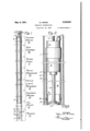
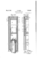
- Fig. 1 is a schematic drawing showing the relation of the several parts of the apparatus to each other, a section of each part being broken away or omitted in order that the view may be made on a larger scale.
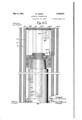
- Fig. 2 is in part an elevation and in part a sectional view of that part of the housing which contains the electric motor and the upper part of a gas chamber.
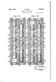
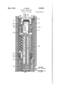
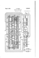
- Fig. 3 is a central vertical section through the upper part of the power pump which is arranged immediately below the gas chamber shown inFig. 2, the view being taken on the line 3-3 of Fig. 6.
- Fig. 4 is a central vertical section taken approximately at right angles to Fig. 3 as indicated by the irregular line 4-4 of Fig. 6.
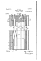
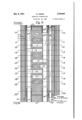
- Fig. 5 is a central vertical section through the lower part of the power pump and shows the fluid channels which connect'the pump to the valve mechanism, the view being taken in the same plane as Fig. 3.
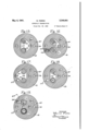
- Fig. 6 is a section plan view taken on the line 66 of Fig. 3.
- Fig.3 is a sectional plan view taken on the line of Fig. 3. V
- Fig. 8 is a sectional plan view taken on the line 8-8 of Fig. 5.
- Fig. 9 is a central vertical section through the valve mechanism, the view being taken on the line 99 of Fig. 10 and immediately below that part of the apparatus shown in Fig. 5.
- Fig. 10 is a sectional plan view taken on the line l0l0 of Fig. 9.
- Fig. 11 is a sectional plan view taken on the line ll-H of Fig. 9.
- Fig. 12 is a sectional plan view taken on the line l2-l2 of 9.
- Fig. 13 is a sectional plan view taken on the line l3-I3 of Fi 9.
- Fig. 14 is a sectional plan view taken on the line 14- of Fig. 9.
- Fig. 15 is a sectional plan view taken on the line l5l5 of Fig. 9.
- Fig. 16 is a sectional plan view taken on the line IB-li of Fig. 9.
- Fig. 1'7 is a sectional plan view taken on the line [1-41 of Fig. 9.
- Fig. 18 is a sectional plan view taken on the line I8-l8 of Fig. 9.
- Fig. 19 is a sectional plan view taken on the line I9-I9 of Fig. 9.
- Fig. 20 is a sectional view taken on the line 20-20 of Fig. 9.
- Fig. 21 is in part a section on the line 2l2l of Fig. 10, showing-the pilot valve and the reversing valve in the positions occupied during an up-stroke of the hydraulic motor, and in part a diagram of the hydraulic'circuit.
- Fig. 22 is a view similar to Fig. 21 but showing the pilot and reversing valves in the positions occupied just before the hydraulic motor completes an up-stroke.
- Fig. 23 is a view similar to Fig. 22 but showing the reversing valve in position to initiate a downstroke of the hydraulic motor.
- Fig. 24 is a vertical section taken on the irregular line 2424 of Figs. 10 and 14.
- Fig. 25 is a vertical section taken,on the irregular line 2525 of Fi 11.
- Fig. 26 is a vertical section taken on the irregular line 26-26 of Fig. 14.
- Fig. 27 is a vertical section taken on the irregular line 21--2l of Fig. 19.
- Fig. 28 is a central vertical section of that part of the apparatus immediately below the valve mechanism shown in Fig. 9, the view being taken on the line 28-28 of Fig. 29 and showing certain connections between the valve mechanism and the reservoir.
- Fig. 29 is a sectional plan view taken on the line 29-29 of Fi 28.
- Fig. 30 is a central vertical section of that part of the apparatus immediately below that part shown in Fig. 28, the view being taken on the same plane as Fig. 28 and showing the hydraulic motor.
- Fig. 31 is a central vertical section showing part of the crude oil pump, the view being a continuation of the view shown in Fig. 30.
- Fig. 32 is avertical section taken on the line 3232 of Fig. 29.
- Fig. 33 is a vertical section taken on the irregular line 3333 of Fig. 29.
- the pumping apparatus has its mechanism arranged within an elongated fluid tight housing l which contains an elongated electric motor A, a gas chamber B, a power pump C, a valve mechanism D, a reservoir E for motive liquid, a hydraulic motor F and an oil pump G, the valves for pump G being arranged in apacker H.
- Housing I which is smaller in diameter than the casing 2 of the oil well in order to provide a space 3 between the housing and the casing through which crude oil may be pumped from the well, is connected by means of a slip joint 4 to packer H which is fixed in casing 2 at or near the bottom thereof and supports at least a part of the weight of the apparatus.
- Packer H has not been illustrated nor described in detail for the reason that such packers are well known and no part of the present invention residestherein. It is deemed sufiicient to state that, as shown schematically in Fig. 1, it has a passage 6 which provides communication between the bottom of the well and the interior of housing a valve i which is arranged in the lower part of passage 6 and permits liquid to flow from the well into passage 6 but prevents it from flowing in the.
- valve 8 which is arranged in the side of passage 8 near the upper end thereof and permits liquid to flow from passage 6 into space 3 but prevents it from flowing in the opposite direction, and a portion 9 which is arranged below valve 8 and is expansible into contact with the wall of casing 2 to support the packer in the casing and to prevent liquid from flowing past it except through passage 6.
- the arrangement is such that, when pump G makes a suction stroke, oil from below packer H will flow through valve I and passage 6 into pump G and, when pump G makes a power stroke, it will eject oil through valve 8 into space 3.
- Housing consists of several sections which have been indicated by the reference numeral I with the exponents a, b, c, d, e, f and g added.
- the upper housing section l is substantially a plain tube sealed at its upper end by a cap III which has a cable attached thereto for raising and lowering the apparatus within casing 2.
- the lower end of section I is connected to and forms a fluid tight 'joint with the upper end of the tubular second section I.
- the adjacent ends of sections I and I are joined by a weld l2 to each other and to 8.. splice ring I3 which is closely fitted therein. This splice ring facilitates the welding, strengthens the joint, and is replaced by a new splice ring should it be necessary to cut the original weld and reweld the joint.
- Electric motor A is fixed in the upper end of section I and adapted to be connected to a power circuit by means of an electric cable Itwhich extends through cap l and makes a fluid tight joint therewith.
- the shaft l of motor A is connected by means'of a coupling l6 to the shaft ll of power pump C which is arranged inside section I.
- the space between the lower end of motor A and the upper end of pump C constitutes a gas chamber B through which shafts l5 and H extend and which contains a non-explosive gas under pressure.
- This gas fills the open spaces in motor A and power pump C and prevents oil from entering the same, thereby preventing the frictional loss that would be caused by churning the oil.
- Figs. 3 to 8 Pump C which is of the type disclosed in Patent No. 2,105,454, is provided with a rotatable cylinder barrel 20 which rotates upon an axis coincident with the axis of housing I.
- Cylinder barrel 2!] is connected at its upper end to shaft IT, as by being formed integral therewith, and it is provided at its lower end with a valve shaft or pintle 2
- is closely fitted for rotation in a bearing bushing 22 fixed in a valve body 23 which is fitted in housing section below cylinder barrel 20.
- Valve body 23 is circular in cross section and is externally slightly arcuate in longitudinal section so that it may adjust itself upon pintle 2
- Cylinder barrel 20 is rotatably supported by a ball thrust bearing 24 having its inner race fixed upon shaft l1 and its outer race fitted in a concentric bore 25 formed in the upper part of a sleeve 26 which is closely fitted in housing section I and has its upper end in contact with the lower end of splice ring l3.
- Shaft l1 extends through but out of contact with a bearing support 21 consisting of an upper circular flange 28, which is concentric with bore 25 and housing and a depending hub 29 which is eccentric thereto as shown in Fig. 4.
- Flange 28 is fitted in bore 25 and rests upon an internal annular flange 30 which is formed in sleeve 26 at the bottom of bore 25.
- Bearing support 21 has a plurality of holes 3
- the outer race of bearing 24 rests upon flange 28 and is held in firm engagement therewith by a ring nut 32 which is threaded into the upper end of sleeve 28 and provided with an external annular flange 33 to engage an internal annular flange 34 formed on the lower end of splice ring l3.
- Ring nut 32 holds the upper end of sleeve 26 against the lower end of splice ring l3 and is prevented from becoming unscrewed by a pin arranged in it and extending into a hole formed partly in splice ring l2 and partly in sleeve 26.
- ! is eccentric and has arranged therein a substantially cylindrical thrust member or drum 35 which has cylinder barrel 26 arranged therein.
- Drum 35 is supported at its upper end by a radial and thrust ball bearing 26 carried by the hub 29 of bearing support 21 and at its lower. end by a roller bearing 31 arranged in the lower end of sleeve 20. Since hub 29 and the lower part of sleeve 26 are eccentric, as shown in Figs. 4, R and I, drum 3! is supported for rotation upon an axis which is offset from the axis of cylinder barrel 20.
- thrust bearing 36 has its outer race fitted in the upper end of drum 35 and retained in position by a snap ring 38 and its inner race fitted on hub 29 and retained in position by a snap ring 33.
- Bearing 31 is shown as having its outer race 46 fitted in the lower end of sleeve 26 and retained therein by a snap ring 4i, its inner race formed integral with the lower end of drum 35 which is reduced in diameter,- and its rollers barrel 20 is rotated, drum 35 will be rotated inunison therewith by the frictional contact of the piston heads with the inner surface of the drum and, since drum 35 is eccentric to cylinder barrel 20, each piston 41 will be forced inward by the drum during' one half-revolution of the cylinder barrel and be permitted to be moved outward by centrifugal force during the other half-revolu tion.
- each piston head will increase as the piston moves outward and decrease as the piston moves inward. Therefore, since drum 35 is rotated substantially in synchronism with cylinder barrel 20 by its contact with the heads of all of the pistons, the head of each piston will move alternately faster and slower than a given point on the inner peripheral surface of drum so that the piston head is caused to roll along the inner surface of drum 35.first in one direction and then the other, thereby causing the piston to rotate as it reciprocates.
- Cylinders 46 are arranged in a plurality of rows and the cylinders in each row communicate with a passage 48 which is formed in cylinder barrel 20 and in pintle 2
- the lower end of each passage 48 extends radially outward to communicate alternately with two segmental ports 48 and 50 which are formed diametrically opposite each other in valve body 23 and its bushing 22 as shown in Figs. 5 and 8.
- Port 48 is connected to reservoir E through passages to be presently described and.
- port 50 is connected through valve mechanism D to hydraulic motor F.
- the passage 48 connected to that row of cylinders is open to port 49 so that the outward moving pistons may draw liquid into their cylinders and, during the other half-revolution, that passage 48 is open to port 50 so that the inward moving pistons will force liquid from their cylinders through the connecting channels and valves to motor F to drive it.
- Port 49 communicates with a plurality of channels 5
- Port 50 communicates with a plurality of channels 53 which extend downward in valve body 23 and then inward into communication with a bore 54 formed in the lower part of valve body 23 concentric with the bore in which pintle 2
- upper end of bore 54 is sealed as by means of a plug 55 threaded therein.
- mayescape through a duct 56 which extends radially therefrom into valve body 23 and then upward to the topof valve body 23-
- This liquid, and all other liquid which may drain onto the top of valve body 23, is permitted to escape through a drain groove 61 formed in the periphery of valve body 23 as shown in Figs. 5 and 8.
- Groove 51 also permits the pressure prevailing in the gas chamberto be communicated to the surface of the oil in the motive liquid reservoir, which surface will usually be at a lower level than valve body 23.
- valve body 23 and the upper end of joint member 52 are shaped to form a fluid tight spherical joint 60 therebetween.
- Support member 64 is closely fitted in the upper part of the third section I of the housing and in the lower part of a splice ring 65 and is supported therein by a pin 66 which is arranged in alined holes formed in splice ring 65 and in support member 64.
- Splice ring 65 is closely fitted in the lower end of housing section I and in the upper end of housing section I and is fixed in position therein by a weld 61 which also joins the adjacent ends of sections l and I to each other.
- Bore 63 communicates intermediate its ends with a suction passage 68 which extends through support member 64 and forms a part of a suction channel 68 through which pump C-draws liquid -from reservoir E.
- - Bore 63 communicates at its Tube 10 has a flange 1
- the upper end of tube 10 is arranged within the bore 54 in valve body 23 and has a ring nut 13 threaded thereon and engaging a sealing ring 14 which is arranged in the lower end of bore 54 and forms a fluid tight joint with ring nut 13.
- Valve body 23 is supported by a helical compression spring 15 which is arranged around tube 10 upon ring nut 12 and reacts against joint member 62, thereby supporting point member 62, joint member 52 and valve body 23.
- Spring 15 also holds ring nut 13 against sealing ring 14 and flange 1i against ring nut 12.
- Ring nut 13 is tightened until passages 43 in pintle 2! are in alinement with ports 48 and 60 in valve body 23 at which time spring 15 is exerting suflicient force to maintain fluid tight joints between flange 1
- Tube 18 is prevented from'turning with nut 13 by a check ring 16 which is arranged in the bottom of bore 63 and provided with notches to receive projec-
Landscapes
- Engineering & Computer Science (AREA)
- General Engineering & Computer Science (AREA)
- Physics & Mathematics (AREA)
- Fluid Mechanics (AREA)
- Mechanical Engineering (AREA)
- Reciprocating Pumps (AREA)
Description
May 6, 1941. w. FERRIS HYDRAULIC TRANSMISSION Filed Feb. 20, 1936 1''! Sheets-Sheet 1 Continued, on F 3.
INVENTOR WALTER F ERR'IS n 4 9/////// V 7//// I W A w O 5 l B ATTO NEY R m m c l 0 M R m T Im mm. W M i5 x 52 vm K/ #1 1'7; Sheets-Sheet 2 w. FERRIS- HYDRAULIC TRANSMISSION Filed Feb. 20; 1956 v m 8 2 3 VmF w \\\\\\\\\\\\\\\\\\\\v\\\\\\\\\\\\\\\\\\ A V///////%V/// m 3 3 J u a m o m 2 as M 6 M w 9. I a a z a L a e a A 4 4 A .y 44/ J J 3 w 7 7 7 4 v \4 3 May 6, 1941.
Continued from Fig.2..
May 6, 1941. w. FERRIS 2,240,901
' HYDRAULIC TRANSMISSION Filed Feb. 20, 1936 17 Sheets-Sheet 4 MW. Rm is. w a m M m g%g Mm //%////3//////////////// w 0 6 w 3m 5 4 2 7 1 2 6 7 W 6 b 2 m x r n. w 5 4V m mm 6 m M 4 w a W F 1 w 5 a w l v 9 O 2 6 4 v 6 5 6 7 Q6 J6 v v 6 M z 6 x V// a I18 2 Y 3 w b 7 w c M f Cant/hue onFi 9 y 1941. w. FERRIS 2,240,901
' HYDRAULIC IRANSMISSION Filed Feb. 20, 1936 I 17 Sheets-Sheet 5 INVENTOR WALTER PERI-HS May 6, 1941. w. FERRIS 2,240,901
I HYDRAULIC TRANSMISSION Filed Feb. 20, 1936 17 Sheets-Sheet 6 INVENTOR ALTER FER'RIS 75 ATTORNEY May 6,1941. w. RRRR IS 2,240,901
ir-1 I i -u May 6, 1941. I wpERRls 2,240,901
HYDRAULI C TRANSMI S S ION Filed Feb. 20, 19 36 17 Sheets-Sheet l0 A INVENTOR WALTER FEH'FHS BY TTORNEY May 6, 1941. w. FERRIS 2,240,901
HYDRAULIC TRANSMISSIQN Filed Feb. 20, 1936 1'7 Sheets-Sheet 12 H. m 7 1 4/ s K May 6, 1941. w. FERRIS HYDRAULIC TRANSMISSION Filed Feb. 20, 1936 17 Sheets-Sheet 15 ZZZ/Z INVENTOR WLTER FEHR'IS- Patented May 6, 1941 HYDRAULIC TRANSMISSION Walter Ferris, Milwaukee, Wis, assignmto The Ollgear Company, Milwank tion of Wisconsin ee, Wia, a corpora- Appllcation February 20, 1936, Serial No. 64,901
20Claim8- This invention relates to hydraulic transmissions of the type having a hydraulic motor, a pump for. supplying liquidto the motor to drive it and automatic valve mechanism for controlling the operation of the motor.
An object of the invention is to provide a hydraulic transmission of the above type which is small enough in diameter to be lowered into the casing of an oil well.
Another object is to provide a small diameter transmission which is capable of operating continuously over long periods of time without requiring to be serviced.
Other objects and advantages will appear from the following description of a hydraulic transmission forming part of a deep well pumping apparatus which includes a reciprocating hydraulic motor for operating a crude oil pump, a power pump for supplying motive liquid to the motor to drive it, valve mechanism for efiecting automatic reversal of the motor, a reservoirfor supplying liquid to the power pump, an electric motor for driving the power pump, and a gas filled chamber for preventing liquid from entering the electric motor, all of which are arranged within a fluid tight casing as shown in the accompanying drawings in which the views are as follows:
Fig. 1 is a schematic drawing showing the relation of the several parts of the apparatus to each other, a section of each part being broken away or omitted in order that the view may be made on a larger scale.
Fig. 2 is in part an elevation and in part a sectional view of that part of the housing which contains the electric motor and the upper part of a gas chamber.
Fig. 3 is a central vertical section through the upper part of the power pump which is arranged immediately below the gas chamber shown inFig. 2, the view being taken on the line 3-3 of Fig. 6.
Fig. 4 is a central vertical section taken approximately at right angles to Fig. 3 as indicated by the irregular line 4-4 of Fig. 6.
Fig. 5 is a central vertical section through the lower part of the power pump and shows the fluid channels which connect'the pump to the valve mechanism, the view being taken in the same plane as Fig. 3.
Fig. 6 is a section plan view taken on the line 66 of Fig. 3.
Fig.3 is a sectional plan view taken on the line of Fig. 3. V
Fig. 8 is a sectional plan view taken on the line 8-8 of Fig. 5.
Fig. 9 is a central vertical section through the valve mechanism, the view being taken on the line 99 of Fig. 10 and immediately below that part of the apparatus shown in Fig. 5.
Fig. 10 is a sectional plan view taken on the line l0l0 of Fig. 9.
Fig. 11 is a sectional plan view taken on the line ll-H of Fig. 9.
Fig. 12 is a sectional plan view taken on the line l2-l2 of 9.
Fig. 13 is a sectional plan view taken on the line l3-I3 of Fi 9.
Fig. 14 is a sectional plan view taken on the line 14- of Fig. 9.
Fig. 15 is a sectional plan view taken on the line l5l5 of Fig. 9.
Fig. 16 is a sectional plan view taken on the line IB-li of Fig. 9.
Fig. 1'7 is a sectional plan view taken on the line [1-41 of Fig. 9.
Fig. 18 is a sectional plan view taken on the line I8-l8 of Fig. 9.
Fig. 19 is a sectional plan view taken on the line I9-I9 of Fig. 9.
Fig. 20 is a sectional view taken on the line 20-20 of Fig. 9.
Fig. 21 is in part a section on the line 2l2l of Fig. 10, showing-the pilot valve and the reversing valve in the positions occupied during an up-stroke of the hydraulic motor, and in part a diagram of the hydraulic'circuit.
Fig. 22 is a view similar to Fig. 21 but showing the pilot and reversing valves in the positions occupied just before the hydraulic motor completes an up-stroke.
Fig. 23 is a view similar to Fig. 22 but showing the reversing valve in position to initiate a downstroke of the hydraulic motor.
Fig. 24 is a vertical section taken on the irregular line 2424 of Figs. 10 and 14.
Fig. 25 is a vertical section taken,on the irregular line 2525 of Fi 11.
Fig. 26 is a vertical section taken on the irregular line 26-26 of Fig. 14.
Fig. 27 is a vertical section taken on the irregular line 21--2l of Fig. 19.
Fig. 28 is a central vertical section of that part of the apparatus immediately below the valve mechanism shown in Fig. 9, the view being taken on the line 28-28 of Fig. 29 and showing certain connections between the valve mechanism and the reservoir.
Fig. 29 is a sectional plan view taken on the line 29-29 of Fi 28.
Fig. 30 is a central vertical section of that part of the apparatus immediately below that part shown in Fig. 28, the view being taken on the same plane as Fig. 28 and showing the hydraulic motor.
Fig. 31 is a central vertical section showing part of the crude oil pump, the view being a continuation of the view shown in Fig. 30.
Fig. 32 is avertical section taken on the line 3232 of Fig. 29.
Fig. 33 is a vertical section taken on the irregular line 3333 of Fig. 29.
' As shown schematically in Fig. 1, the pumping apparatus has its mechanism arranged within an elongated fluid tight housing l which contains an elongated electric motor A, a gas chamber B, a power pump C, a valve mechanism D, a reservoir E for motive liquid, a hydraulic motor F and an oil pump G, the valves for pump G being arranged in apacker H.
Housing I, which is smaller in diameter than the casing 2 of the oil well in order to provide a space 3 between the housing and the casing through which crude oil may be pumped from the well, is connected by means of a slip joint 4 to packer H which is fixed in casing 2 at or near the bottom thereof and supports at least a part of the weight of the apparatus.
Packer H has not been illustrated nor described in detail for the reason that such packers are well known and no part of the present invention residestherein. It is deemed sufiicient to state that, as shown schematically in Fig. 1, it has a passage 6 which provides communication between the bottom of the well and the interior of housing a valve i which is arranged in the lower part of passage 6 and permits liquid to flow from the well into passage 6 but prevents it from flowing in the. opposite direction, a valve 8 which is arranged in the side of passage 8 near the upper end thereof and permits liquid to flow from passage 6 into space 3 but prevents it from flowing in the opposite direction, and a portion 9 which is arranged below valve 8 and is expansible into contact with the wall of casing 2 to support the packer in the casing and to prevent liquid from flowing past it except through passage 6.
The arrangement is such that, when pump G makes a suction stroke, oil from below packer H will flow through valve I and passage 6 into pump G and, when pump G makes a power stroke, it will eject oil through valve 8 into space 3.
Housing consists of several sections which have been indicated by the reference numeral I with the exponents a, b, c, d, e, f and g added.
The upper housing section l is substantially a plain tube sealed at its upper end by a cap III which has a cable attached thereto for raising and lowering the apparatus within casing 2. The lower end of section I is connected to and forms a fluid tight 'joint with the upper end of the tubular second section I. As shown in Fig. 2, the adjacent ends of sections I and I are joined by a weld l2 to each other and to 8.. splice ring I3 which is closely fitted therein. This splice ring facilitates the welding, strengthens the joint, and is replaced by a new splice ring should it be necessary to cut the original weld and reweld the joint.
Electric motor A is fixed in the upper end of section I and adapted to be connected to a power circuit by means of an electric cable Itwhich extends through cap l and makes a fluid tight joint therewith. The shaft l of motor A is connected by means'of a coupling l6 to the shaft ll of power pump C which is arranged inside section I.
The space between the lower end of motor A and the upper end of pump C constitutes a gas chamber B through which shafts l5 and H extend and which contains a non-explosive gas under pressure. This gas fills the open spaces in motor A and power pump C and prevents oil from entering the same, thereby preventing the frictional loss that would be caused by churning the oil.
Figs. 3 to 8 Pump C, which is of the type disclosed in Patent No. 2,105,454, is provided with a rotatable cylinder barrel 20 which rotates upon an axis coincident with the axis of housing I. Cylinder barrel 2!] is connected at its upper end to shaft IT, as by being formed integral therewith, and it is provided at its lower end with a valve shaft or pintle 2| which is also shown as being formed integral therewith.
Pintle 2| is closely fitted for rotation in a bearing bushing 22 fixed in a valve body 23 which is fitted in housing section below cylinder barrel 20. Valve body 23 is circular in cross section and is externally slightly arcuate in longitudinal section so that it may adjust itself upon pintle 2| by rocking slightly in housing section l Cylinder barrel 20 is rotatably supported by a ball thrust bearing 24 having its inner race fixed upon shaft l1 and its outer race fitted in a concentric bore 25 formed in the upper part of a sleeve 26 which is closely fitted in housing section I and has its upper end in contact with the lower end of splice ring l3.
Shaft l1 extends through but out of contact with a bearing support 21 consisting of an upper circular flange 28, which is concentric with bore 25 and housing and a depending hub 29 which is eccentric thereto as shown in Fig. 4. Flange 28 is fitted in bore 25 and rests upon an internal annular flange 30 which is formed in sleeve 26 at the bottom of bore 25.
Bearing support 21 has a plurality of holes 3| extending through it to permit liquid to drain from above and to permit the gas pressure prevailing in chamber B to extend into section l The outer race of bearing 24 rests upon flange 28 and is held in firm engagement therewith by a ring nut 32 which is threaded into the upper end of sleeve 28 and provided with an external annular flange 33 to engage an internal annular flange 34 formed on the lower end of splice ring l3. Ring nut 32 holds the upper end of sleeve 26 against the lower end of splice ring l3 and is prevented from becoming unscrewed by a pin arranged in it and extending into a hole formed partly in splice ring l2 and partly in sleeve 26.
The portion of sleeve 26 below flange 3|! is eccentric and has arranged therein a substantially cylindrical thrust member or drum 35 which has cylinder barrel 26 arranged therein. Drum 35 is supported at its upper end by a radial and thrust ball bearing 26 carried by the hub 29 of bearing support 21 and at its lower. end by a roller bearing 31 arranged in the lower end of sleeve 20. Since hub 29 and the lower part of sleeve 26 are eccentric, as shown in Figs. 4, R and I, drum 3! is supported for rotation upon an axis which is offset from the axis of cylinder barrel 20.
As shown, thrust bearing 36 has its outer race fitted in the upper end of drum 35 and retained in position by a snap ring 38 and its inner race fitted on hub 29 and retained in position by a snap ring 33. Bearing 31 is shown as having its outer race 46 fitted in the lower end of sleeve 26 and retained therein by a snap ring 4i, its inner race formed integral with the lower end of drum 35 which is reduced in diameter,- and its rollers barrel 20 is rotated, drum 35 will be rotated inunison therewith by the frictional contact of the piston heads with the inner surface of the drum and, since drum 35 is eccentric to cylinder barrel 20, each piston 41 will be forced inward by the drum during' one half-revolution of the cylinder barrel and be permitted to be moved outward by centrifugal force during the other half-revolu tion.
The linear speed of each piston head will increase as the piston moves outward and decrease as the piston moves inward. Therefore, since drum 35 is rotated substantially in synchronism with cylinder barrel 20 by its contact with the heads of all of the pistons, the head of each piston will move alternately faster and slower than a given point on the inner peripheral surface of drum so that the piston head is caused to roll along the inner surface of drum 35.first in one direction and then the other, thereby causing the piston to rotate as it reciprocates.
Cylinders 46 are arranged in a plurality of rows and the cylinders in each row communicate with a passage 48 which is formed in cylinder barrel 20 and in pintle 2| and extends for the greater part of its length parallel to the axes thereof as shown in Figs. 3 and 6. The lower end of each passage 48 extends radially outward to communicate alternately with two segmental ports 48 and 50 which are formed diametrically opposite each other in valve body 23 and its bushing 22 as shown in Figs. 5 and 8. Port 48 is connected to reservoir E through passages to be presently described and. port 50 is connected through valve mechanism D to hydraulic motor F. Throughout the greater part of the'half revo lution during which the pistons 41 in one row of cylinder 46 are moving outward, the passage 48 connected to that row of cylinders is open to port 49 so that the outward moving pistons may draw liquid into their cylinders and, during the other half-revolution, that passage 48 is open to port 50 so that the inward moving pistons will force liquid from their cylinders through the connecting channels and valves to motor F to drive it.
' Port 49 communicates with a plurality of channels 5| which extend downward through valve body 23 into communication with a hollowjoint member 52. Port 50 communicates with a plurality of channels 53 which extend downward in valve body 23 and then inward into communication with a bore 54 formed in the lower part of valve body 23 concentric with the bore in which pintle 2| is journaled. In order to prevent the high pressure in bore 54 from acting upon pintle 2 l', upper end of bore 54 is sealed as by means of a plug 55 threaded therein.
Leakage liquid which collects'between plug 55 and the lower end of pintle 2| mayescape through a duct 56 which extends radially therefrom into valve body 23 and then upward to the topof valve body 23- This liquid, and all other liquid which may drain onto the top of valve body 23, is permitted to escape through a drain groove 61 formed in the periphery of valve body 23 as shown in Figs. 5 and 8. Groove 51 also permits the pressure prevailing in the gas chamberto be communicated to the surface of the oil in the motive liquid reservoir, which surface will usually be at a lower level than valve body 23.
The lower end of valve body 23 and the upper end of joint member 52 are shaped to form a fluid tight spherical joint 60 therebetween. The lower part of a bore 63 formed in a support member 64 upon the axis of housing I.
Support member 64 is closely fitted in the upper part of the third section I of the housing and in the lower part of a splice ring 65 and is supported therein by a pin 66 which is arranged in alined holes formed in splice ring 65 and in support member 64.
Splice ring 65 is closely fitted in the lower end of housing section I and in the upper end of housing section I and is fixed in position therein by a weld 61 which also joins the adjacent ends of sections l and I to each other.
Bore 63 communicates intermediate its ends with a suction passage 68 which extends through support member 64 and forms a part of a suction channel 68 through which pump C-draws liquid -from reservoir E.- Bore 63 communicates at its Tube 10 has a flange 1| arranged upon its lower end and engaged by a ring nut 12 which is threaded into the lower part of bore 63 and limits the upward movement of the tube 10, ring nut 12 forming a fluid tight joint with flange 11. The upper end of tube 10 is arranged within the bore 54 in valve body 23 and has a ring nut 13 threaded thereon and engaging a sealing ring 14 which is arranged in the lower end of bore 54 and forms a fluid tight joint with ring nut 13.
Valve body 23 is supported by a helical compression spring 15 which is arranged around tube 10 upon ring nut 12 and reacts against joint member 62, thereby supporting point member 62, joint member 52 and valve body 23. Spring 15 also holds ring nut 13 against sealing ring 14 and flange 1i against ring nut 12.
Ring nut 13 is tightened until passages 43 in pintle 2! are in alinement with ports 48 and 60 in valve body 23 at which time spring 15 is exerting suflicient force to maintain fluid tight joints between flange 1| and ring nut 12 and between ring nut 13 and sealing ring 14. Tube 18 is prevented from'turning with nut 13 by a check ring 16 which is arranged in the bottom of bore 63 and provided with notches to receive projec-
Priority Applications (1)
| Application Number | Priority Date | Filing Date | Title |
|---|---|---|---|
| US64901A US2240901A (en) | 1936-02-20 | 1936-02-20 | Hydraulic transmission |
Applications Claiming Priority (1)
| Application Number | Priority Date | Filing Date | Title |
|---|---|---|---|
| US64901A US2240901A (en) | 1936-02-20 | 1936-02-20 | Hydraulic transmission |
Publications (1)
| Publication Number | Publication Date |
|---|---|
| US2240901A true US2240901A (en) | 1941-05-06 |
Family
ID=22058972
Family Applications (1)
| Application Number | Title | Priority Date | Filing Date |
|---|---|---|---|
| US64901A Expired - Lifetime US2240901A (en) | 1936-02-20 | 1936-02-20 | Hydraulic transmission |
Country Status (1)
| Country | Link |
|---|---|
| US (1) | US2240901A (en) |
Cited By (5)
| Publication number | Priority date | Publication date | Assignee | Title |
|---|---|---|---|---|
| US2428035A (en) * | 1943-06-16 | 1947-09-30 | Stewart Warner Corp | Hydraulically controlled dispensing pump |
| US2455022A (en) * | 1944-08-08 | 1948-11-30 | Benjamin F Schmidt | Submersible double-acting fluid piston deep well pump |
| WO2002036968A1 (en) * | 2000-10-31 | 2002-05-10 | Halliburton Energy Services, Inc. | Low power miniature hydraulic actuator |
| US6543544B2 (en) | 2000-10-31 | 2003-04-08 | Halliburton Energy Services, Inc. | Low power miniature hydraulic actuator |
| EP1930540A1 (en) | 2000-10-31 | 2008-06-11 | Halliburton Energy Services, Inc. | Low power miniature hydraulic actuator |
-
1936
- 1936-02-20 US US64901A patent/US2240901A/en not_active Expired - Lifetime
Cited By (5)
| Publication number | Priority date | Publication date | Assignee | Title |
|---|---|---|---|---|
| US2428035A (en) * | 1943-06-16 | 1947-09-30 | Stewart Warner Corp | Hydraulically controlled dispensing pump |
| US2455022A (en) * | 1944-08-08 | 1948-11-30 | Benjamin F Schmidt | Submersible double-acting fluid piston deep well pump |
| WO2002036968A1 (en) * | 2000-10-31 | 2002-05-10 | Halliburton Energy Services, Inc. | Low power miniature hydraulic actuator |
| US6543544B2 (en) | 2000-10-31 | 2003-04-08 | Halliburton Energy Services, Inc. | Low power miniature hydraulic actuator |
| EP1930540A1 (en) | 2000-10-31 | 2008-06-11 | Halliburton Energy Services, Inc. | Low power miniature hydraulic actuator |
Similar Documents
| Publication | Publication Date | Title |
|---|---|---|
| US3223046A (en) | Rotary radial piston machines | |
| US3174436A (en) | Radial pump | |
| CN106837725A (en) | Two-dimensional axial plunger displacement pump | |
| US2240901A (en) | Hydraulic transmission | |
| US8226383B2 (en) | Downhole pump | |
| CN104153986A (en) | Axial plunger hydraulic pump for hydraulic return stroke | |
| US3186352A (en) | Variable displacement piston pump | |
| US3859011A (en) | Diaphragm pumps | |
| CN115370567B (en) | Plunger pump | |
| CN206562977U (en) | Two-dimensional axial plunger pump | |
| CN104100482B (en) | Wear-resistant axial plunger type hydraulic pump | |
| CN108799037B (en) | Crawler-type hydraulic water injection pump | |
| US2674196A (en) | Piston assembly for axial type hydrodynamic machines | |
| CN107795447A (en) | Entrance boosting type two dimension double crosslinking piston pump | |
| US20020044873A1 (en) | High pressure fuel pump | |
| CN204082514U (en) | Wear-resistant axial plunger type hydraulic pump | |
| US3785753A (en) | Electric drives for centrifugal pumps | |
| US3082693A (en) | Starting valve for variable displacement hydraulic pump | |
| US2789515A (en) | Variable stroke variable pressure pump or compressor | |
| US2373449A (en) | Pump | |
| US1964244A (en) | Variable delivery radial pump | |
| US2932312A (en) | Valve system for pumps | |
| US2816515A (en) | Pumps | |
| CN212898899U (en) | Submersible single-cylinder plunger oil pump | |
| DE102014010416B3 (en) | Hydraulic motor for driving ancillaries |