US2220249A - Gelatin band shifting and tightening means for duplicating machines - Google Patents
Gelatin band shifting and tightening means for duplicating machines Download PDFInfo
- Publication number
- US2220249A US2220249A US273263A US27326339A US2220249A US 2220249 A US2220249 A US 2220249A US 273263 A US273263 A US 273263A US 27326339 A US27326339 A US 27326339A US 2220249 A US2220249 A US 2220249A
- Authority
- US
- United States
- Prior art keywords
- spindle
- band
- drum
- holding
- lever
- Prior art date
- Legal status (The legal status is an assumption and is not a legal conclusion. Google has not performed a legal analysis and makes no representation as to the accuracy of the status listed.)
- Expired - Lifetime
Links
Images

Classifications
-
- B—PERFORMING OPERATIONS; TRANSPORTING
- B41—PRINTING; LINING MACHINES; TYPEWRITERS; STAMPS
- B41L—APPARATUS OR DEVICES FOR MANIFOLDING, DUPLICATING OR PRINTING FOR OFFICE OR OTHER COMMERCIAL PURPOSES; ADDRESSING MACHINES OR LIKE SERIES-PRINTING MACHINES
- B41L9/00—Apparatus for indirectly duplicating from hectographic originals by means of hectographic intermediaries or transfer surfaces, i.e. "dry duplicators"
- B41L9/10—Apparatus for indirectly duplicating from hectographic originals by means of hectographic intermediaries or transfer surfaces, i.e. "dry duplicators" with rotary cylinders carrying sheets of hectographic gelatin-paper
-
- B—PERFORMING OPERATIONS; TRANSPORTING
- B41—PRINTING; LINING MACHINES; TYPEWRITERS; STAMPS
- B41L—APPARATUS OR DEVICES FOR MANIFOLDING, DUPLICATING OR PRINTING FOR OFFICE OR OTHER COMMERCIAL PURPOSES; ADDRESSING MACHINES OR LIKE SERIES-PRINTING MACHINES
- B41L9/00—Apparatus for indirectly duplicating from hectographic originals by means of hectographic intermediaries or transfer surfaces, i.e. "dry duplicators"
- B41L9/04—Apparatus for indirectly duplicating from hectographic originals by means of hectographic intermediaries or transfer surfaces, i.e. "dry duplicators" with flat supports over which gelatin-paper is stretched
- B41L9/08—Apparatus for indirectly duplicating from hectographic originals by means of hectographic intermediaries or transfer surfaces, i.e. "dry duplicators" with flat supports over which gelatin-paper is stretched and with devices for rolling-in and securing hectographic gelatin-paper webs
Definitions
- My invention relates to duplicating machines of the hectograph type employing gelatin duplicating pads, and it has for its object the provision of a new and improved form and arrangement of parts by which the gelatin pad in the form of a long band may be easily and quickly shiftedand tightened in operative position so as to be held securely in place for operation.
- the spindle upon which the opposite end portion of the band is wound is adapted to be 40 driven by power through a manually controllable clutch in the direction for winding the band on the spindle, there being an auxiliary clutch driving mechanism arranged at a suitable point in the train of driving means adapted to yield auto- 45 matically for preventing breakage of the parts when the resistance with respect to further driving becomes unduly great.
- Control means is provided for releasing the latching device for one spindle and for throwing the driving clutch into 50 operation for effecting a transfer of a portion of the gelatin band from one spindle to the other.
- the arrangement is such that upon a return movement of the operating member of said control means the latching device is first thrown 55 into operation while the clutc till operative so as to permit continued rotation of the winding spindle for tightening the band on the drum, after which upon further movement of the operating member the clutch is thrown out of operation at about the completion of the return 5 movement of said operating member.
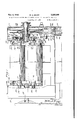
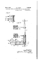
- Fig. 1 is a vertical sectional view of the upper portion of my improved machine, being taken on a somewhat enlarged scale substantially at the line i -'-i of Fig. 4;
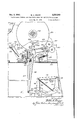
- Figs. 2, 3 and 4 are vertical cross sectional views taken on a smaller scale at the line 2-2, the line 3-3, and the line 4-4, respectively, of Fig. 1;
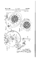
- Fig. 5 is a vertical sectional view taken on an enlarged scale at the line 5-5 of Fig. 1;
- Fig. 6 is a view similar to Fig. 5 but showing a changed position of some of the parts;
- Fig. '7 is a view similar to a portion of Fig. 1 but showing many of the parts in side elevation instead of in section; i
- Figs. 8 and 9 are face'views of a part of the apparatus as shown in Fig. 7 but showing changed positions of certain of the parts;
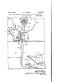
- Fig. 10 is a horizontal sectional view taken substantially at the line lfll 0 of Fig. 3;
- Fig. 11 is a horizontal sectional view taken substantially at the line H--l l of Fig. 2.
- 20 indicates a cabinet formed of sheet metal having housing members 2
- a sheet metal wall member 30 constituting the face of the drum.
- the sheet metal member 30 does not extend completely about the drum, being discontinued at the left hand side of the drum as shown in Fig. 4, so' as to give the drum, a segmental form, as is usual in the hectograph type of machine.
- I have mounted spindles 3
- the end portion of the spindle is inserted within a socket 33 formed on the end plate I 26, serving to compress a coiled spring 34.
- the opposite end of the spindle is then brought into position opposite to a short pin 35 rotatably mounted upon the end plate 21 of the drum, 9.
- lug 36 carried by the pin serving by engagement with-the spindle to connect the spindle and the pin for rotation together when the spindle has been brought into engagement with the lug.
- the spindle 32 is normally inserted into the machine with a long hectograph band 31 wound thereon.
- the end portion of the band 31 is drawn into position about the plate 30 of the drum and is connected with the spindle 3
- Means is provided for driving the spindle 3
- This means comprises a gear 38 rotatably mounted upon the pin and adapted to be operatively connected with said pin by means as hereinafter described.
- the gear 38 is driven by an idler pinion 39 (see Fig. 4) rotatably mounted upon the end plate 21, such idler pinion 39 being in meshing relationship with a pinion 40 fixedly connected with a clutch member 4
- a cooperating clutch member 42 is fixedly mounted uponthe shaft 29, the arrangement being such 40 that the clutch member 4
- the clutch member 42 is driven by a large gear 43 rigidly connected with the clutch member, such gear 43 in turn suitable source of power, pinions 44 and 45 of such train of gearing being shown in the drawings, see Fig. 2.
- the means for connecting the gear38 with the shaft or pin 35 about-which it is mounted comprises a plate member 46 which is fixedly connected with said shaft or pin 35 so as to rotate with said shaft inside of a flange 41 carried by 55 the gear 38.
- a plate member 46 which is fixedly connected with said shaft or pin 35 so as to rotate with said shaft inside of a flange 41 carried by 55 the gear 38.
- plate member 46 is provided with a series of radially disposed sockets 48 therein, each of said sockets being provided with a coiled spring49 and a spherical ball 56 therein for engagement 0 with openings 5
- the arrangement is such that the balls 56 are normally pressed by the springs 49 into engagement with the inner end portion of the openings 5
- the balls 56 are forced inwardly against the action of the springs 49 so as to permit the flange 41 to move circum- 70 ferentially with respect to the plate 46, as is indicated by reference to Fig. 6.
- the gelatin band 31 extends about a roller 52 which is rotatably mounted between the end plates 26 and 21 of the drum.
- roller 52 is Provided at one with a pinion 53 (see Fig. l) which is driven by an idler pinion 54 meshing with the gear 36, as is shown in Fig. 4.
- the arrangement is such that the surface speed of the roller 52 corresponds substantially to the speed at which the gelatin band 31 moves when being shifted with respect to the drum 25.
- a pawl 55 pivotally mounted upon the end plate 21 of the drum in position to engage a ratchet gear 56 carried by the plate member 46.
- a spring 51 is provided holding the dog 55 normally in engagement with the ratchet wheel 56, as is shown in Fig. 5, the spring 51 bearing at one end against a lug 58 carried by the end plate 21.
- the means for holding the spindle 32 against rotation in counterclockwise direction in Fig. 4 comprises a ratchet wheel 59 fixedly mounted upon the pin 35 with which the spindle 32 is rotatably connected in Fig. 1.
- a pawl or dog 60 pivotally mounted in position and normally held by a coiled spring 6
- the parts With the gelatin band 31 in tightened condition upon the drum 25 and with the pawls 55 and 60 holding the spindles against rotary movement in thedirection for unwinding the band from the spindles, the parts are in condition for normal operation of the machine.
- ! is released so as to permit the spindle 32 to rotate in the direction for unwinding the band therefrom. Power is then applied through the driving means above described for rotating the spindle 3
- the pawl 60 is again thrown into operative position for preventing further unwinding of the gelatin band from the spindle 32, the arrangement being such that the drive of the spindle 3
- This serves to tighten the gelatin band 31 upon the drum 25, such tightening effect being continued until the tension upon the band becomes so great as to resist further rotation of the spindle 3
- Suchincreased tension causes the retraction of the balls 50 as above described for permitting the gear 38 to continue its rotation without corresponding rotation of the spindle 3
- is then to be moved out of engagement with the clutch member 42 so as to stop the application of' power through the gear 33 to the spindle 3
- is then to be moved out of engagement with the clutch member 42 so as to stop the application of' power through the gear 33 to the spindle 3
- the drum 25 is driven by power applied from the gear 43.
- the means for applying power from the gear 43 to the drum comprises a ratchet wheel 62 operatively connectedwith the gear 43 so as to rotate yieldingly therewith.
- a second large gear 63 is fixedly mounted upon the shaft '23 adiacent'to the large gear 43, such gear 63 being provided with a pawl 64 pivotally mounted thereon in position to engage the ratchet wheel 62 for causing the gear 63 to rotate with the gear 43.
- the means for effecting an operative connection between the gears 43 and 63 is shown particularly in Fig.
- two pedals 69 and 19 are provided for controlling the operation of the machine.
- the pedal- 69 is fixedly mounted upon a rock shaft ll journaled in the cabinet 29, such shaft ll being provided at one end with an upwardly extending arm 12 which is pivotally connected by a link 13 with the upwardlyextending arm 14 of a bellcrank lever also pivotally mounted in the cabinet 29, the forwardly extending arm 15 of the bellcrank being pivotally connected by a link 16 with the end of the plate 65.
- a spring 11 is connected between the upper end portion of the arm 44 and the bracket in which the shaft 'II is mounted, said spring serving normally to hold the pedal 69 and the plate 65 both in raised position.
- the arrangement is such that when the drum 25 is standing stationary, with the gear being driven continuously by power, a downward stroke of the pedal 69 serves to actuate the means for operatively connecting the gear 58 with the gear 48 40 for causing the drum to move through a single 45 end being provided with an upwardly extending arm 19 fixedly mounted on the sleeve, such arm being pivotally connected by means of a link 86 with the upwardly extending arm 8
- the horizontally extending arm 83 of the bellcrank lever is pivotally connected by means of a link 84 with two toggle links 85 and 86 for operating the clutch member 4
- a coiled spring 81 connected between the bellcrank lever arm 8
- the links 85 and 85 are pivotally connected with the upper end portion of the link 84 by means of a bolt 88, the link 86 being pivotally mounted upon the frame plate 23, and the link. 85 being pivotally connected at its outer end with the lower end portion of a vertically disposed lever 89 which is pivotally mounted at an intermediate point upon a frame member 90 .rising from the cabinet 29. upper end portion, the lever 89' is in the form of a yoke (see Fig. 3) which is operatively connected with the clutch member 4
- Th arrangement is such that when the link 84 is drawn downwardly for bringing the pivotally connected toggle links 85 and 85 into aligned position with respect to each other the lever 89 is movedin At its clockwise direction from the positlon'shown in Fig. 7 to the position as shown in Fig. 8 for moving the clutch member 4
- a, spring 99-41 is connected between the frame member 90 and the link 84 for assisting the spring 81 in moving the links 85 and 86 into their upwardly buckled positions.
- the pedal I0 is given a downward stroke, serving to release the pawl 69 from the ratchet wheel 59 so as to permit the spindle 32 to rotate in the direction for unwinding the gelatin band therefrom and serving also to move the clutch member 4
- This serves to drive the spindle 3
- the operator relaxes the pressure upon the pedal 19 so as to permit the spring 81 to give the pedal and its connected parts a partial return movement.
- the arrangement of the parts is such that when the pedal 10 has reached a predetermined intermedi-' have been returned to its operative position as shown, in Fig, 3 for preventing further rotation of the spindle 32 in the direction for unwinding the gelatin band therefrom while at the same time the clutch member I remains in effective engagement with the clutch member 42 as shown in Fig. 9.
- the desired tightening of the gelatin band is effected, the completion of the tightening operation being indicated by a slight clicking noise which can be heard when the balls 50 are carried past the openings II in the continued rotation of the gear 38 after the stoppage of the plate member 46.
- the pressure upon the pedal is completely removed, whereupon the spring 81 serves to return the parts to their normal position as-shown in Fig. 7, with the clutch member 4
- the roller 99 would be brought downwardly upon the upper face of the arm 96.
- the arm 96 would be moved in clockwise direction in Fig. 3 for permitting the roller 99 to be disengaged from the arm 96 without the application of undue pressure upon any of the parts.
- a duplicating machine the combination of a drum, means for rotating the drum, spindles rotatably mounted on the drum adapted to have 65 the opposite end portions of a gelatin band wound thereon with the intermediate portion of said band wrapped about a portion of the drum, releasable means for holding one of said spindles against rotation in the direction for unwinding 70 the band therefrom, means for driving the other erating member adapted by a portion of a stroke in one direction to cause said first-named spindle holding means to be operative for holding one of -the spindles against rotation while the other spindle rotates and adapted by a later portion of a stroke in the same direction to stop the drive of said other spindle.
- the combination rotatably mounted on the drum adapted to have the opposite end portions of a gelatin band wound thereon with the intermediate portion of said band wrapped about a portion of the drum, releasable means for holding one of said spindles against rotation in the direction for unwinding the band therefrom, means comprising a releasable clutch for driving the other of said spindles in the direction for winding the band thereon, means for holding said other spindle against rotation in the direction for unwinding the band therefrom, and control means for said firstnamed spindle holding means and said clutch comprising an operating member adapted by a movement inone direction to cause said firstnamed spindle holding means to be operative for holding said one spindle against rotation while the other spindle rotates and adapted by further movement in the same direction to open said clutch for stopping the drive of said other spindle.
- a drum means for rotating the drum, spindles rotatably mounted on the drum adapted to have opposite end portions of a gelatin band wound thereon with the intermediate portion of said band wrapped about a portion of the drum, releasable means serving when in operative position to hold one of said spindles positively against rotation in the direction for unwinding the gelatin band therefrom, means for driving the other of said spindles in the direction for winding the band thereon, means for holding said other spindle against rotation in the direction for unwinding the band therefrom, and means comprising a single control member adapted in one position to hold the parts in an operative position for permitting free unwinding of the gelatin band from said one spindle and for driving said other spindle, adapted'in another position to cause said one spindle to be held against rotation in the direction for unwinding the gelatin band therefrom while the drive of,said other spindle is continued, and adapted in a of a drum, means for rotating the
- the combination is of a drum-means for rotating the drum, spindles rotatably mounted on the drum-adapted to-have' opposite end portions of a gelatin band wound thereon with the intermediate portion of said band wrapped about a portion of the drum, re-
- leasable latch means for holding one of said spindles positively-against rotation in the direction for unwinding the band therefrom, means fordriving the other of said spindles in the direction for winding the band thereon, means for direction for unwinding the band therefrom, and control means adapted by'a stroke in one direction to throw said latch means out of holding position and to throw said driving means into operation for transferring a-portion of said band from one spindle to the other, and adapted on the first portion of a return stroke in the reverse direction to throw said latch means into operative holding position for tightening the band during the continued operation of the driving means, and adapted by further movement, in said reverse direction to throw said driving means out of operation.
- a drum Ina duplicating machine, the combination of a drum, means for rotating the drum, spindles rotatably mounted on the drum adapted to have the opposite end portions of a gelatin band wound thereon with the intermediate portion of said band wrapped about a portion of the drum, releasable means for holding one of said spindles against rotation in the direction for unwinding the-band therefrom, means for driving the other of said spindles in the direction for winding the band thereon and comprising tension-releasable means adapted to yield automatically when the pressure thereon reaches a predetermined value, means; for holding said other spindle again t rocause the drive of said'other spindle-to be dis,-
- spindle holding means and adapted by, the initial portion of a stroke in one direction to causesaid first-named spindle holding means to be ,oper-' ative for holding said one spindle,- against rotation in-the direction for unwinding theb'andf therefrom while the other spindle rotates s'o as to tighten said band on the drum, and adapted by a later portion of a stroke in said-one direcf-tion to stop the .drive of said other spindle.
- a duplicating machine the combination of a rotatably mounted drum, means for rotating thedrum, spindlesr'otatably mounted on the drum adapted to have the opposite end portions of a gelatin band wound thereon with the intermediate portion of said band wrapped about a .portion or the drum so that the band may be transferred readily from one spindle to the other, means for driving said other spindle in the direction for winding the band thereon and comprising driving means adapted to yield and slip when the tension thereon reaches a predetermined maximum, means for holding said other spindle against rotation in the direction for unwinding the band therefrom, releasable means for holding said one spindle against rotation in the direction for unwinding the band therefrom adapted when said other spindle is being driven to cause said band to be tightened so as to bring about slippage of said yielding driving means, and means comprising a single control memberfor said driving means and said second-named spindle holding means adapted by the initial portion ofa stroke in one direction to
- a duplicating machine the combination of a rotatably mounted drum, means for rotating the drum, spindles rotatablymounted on the drum adapted to have the opposite end portions of a gelatin band wound thereon with the intermediate portion of saidband wrapped about a portion of the drum so that the band may be transferred readily from one spindle to'the other, means for driving said other spindle in the diretion for winding the band thereonand comprising driving means adapted to yield and slip when the tension thereon reaches a predetermined maxi-' mum, means for holding said other spindle against rotation in the direction for unwinding the band therefrom, releasable means for holding said one spindle against rotation in the direction for unwinding the band therefrom adapted when said other spindle is being driven to cause said band to be,tightened so as to bring about slipp e of said yielding driving means, a pedal member piv- 4 said other spindle to be driven in the direction.
- a duplicating machine the combination of a rotatably mounted drum, two spindles rotatably mounted on the drum adapted to have the end portions of a gelatin band wound thereon with, the intermediate portion of said band wrapped. about a portion of the drum so as to enable the band to be transferred readily from 55 one spindle to -the other, means for driving said other spindle for effecting a transfer of the band thereto, means for holding said other spindle against rotation in the direction for-unwinding the band therefrom, means comprising a mem- 60 ber movably mounted on said drum adapted when in operative position to hold said one spindle against rotation in the direction for unwind,-
- a rotatably mounted drum, two spindles rotatably mounted on the drum adapted to have 15 the end portions of a gelatin band wound there-v on with the intermediate portion of said band wrapped about a portion of the drum so as to enable the band to be transferred readily from one spindle to the other, means for driving said 20 other spindle for effecting a transfer of the band thereto, means for holding said other spindle against rotation in the direction for unwinding the band therefrom, means comprising a member movably mounted on said drum adapted when 25 in operative position to holdsaid one spindle against rotation in the direction for unwinding the gelatin band therefrom, yielding means normally holding said movably mounted member in operative position, means for rotating the drum, means comprising a lever adapted by movements in opposite directions to throw said spindle driving means into and out of operation, a second lever pivotally mounted adjacent to said drum, an arm pivotally mounted on said second lever, stop means for limiting the swinging movement
- said second lever is first retracted so as to cause said movably mounted spindle holding means to become operative while the drive of said other spindle continues for tightening the gelatin band on the drum and that thereafter upon the continued stroke of said first-named lever said spindle driving means is thrown out of operation.
- latch means pivotally mounted on said drum adapted when in operative position to hold said inents in opposite directions to throw said spindle driving means into and out of operation
- operating means movably mounted adjacent to said drum, adapted by an operative movement when the drum is held in a predetermined fixed position to engage said latch means and to move such latch means out of holding position so as to permit the band to unwind from said one spindle
- a rotatably mounted drum means for rotating the drum, two spindles rotatably mounted on the drum adapted to have the end portions of a gelatin band wound thereon with the intermediate portion of said .band wrapped about a portion'of the drum so as to enable the band to be transferred readily from one spindle to the other, means for driving said other spindle for effecting a transfer of the band thereto, means for holding said .other spindle against rotation in the direction for unwinding the band therefrom, latch means pivotally mounted on said drum adapted when in operative position to hold said' one spindle against rotation in the direction for unwinding the gelatin band therefrom, a spring normally holding said latch means in operative position, means comprising a lever adapted by movements in opposite directions to throw said spindle driving means into and out of operation, a second lever pivotally mounted adjacent to 40 said drum, an arm pivotally mounted on said second lever, stop means for limiting the swinging movement of said arm on said lever, yield
- a rotatably mounted drum means for. rotating the drum, spindles rotatably mounted on the drum adapted to have the opposite end portions of a gelatin band wound thereon with the intermediate portion of said band wrapped about a portion of the drum so that the band may be transferred readily-from one spindle to the other, means for driving said other spindle in the direction for winding the band thereon and comprising driving means adapted to yield and slip when the tension thereon reaches a predetermined maximum, means for holding said other spindle against rotation in the direction for unwinding the band therefrom, means comprising a member movably mounted on said drum adapted whenin operative position to hold said one spindle positively against rotation in the direction for unwinding the gelatin band therefrom, yielding means normally holding said movable member in operative position, means comprising a lever adapted by movement in opposite directions to throw said spindle driving means into and out of operation, operating means movably mounted acfiacent to said drum
- a rotatably mounted drum means for rotating the drum, spindles rotatably mounted on the drum adapted to have the opposite end portions of a gelatin band wound' thereon with the intermediate portion of said band wrapped about a portion of the drum so that the band may be transferred readily from one spindle to the other, means for driving said other spindle in the direction for winding the band thereon and comprising driving means adapted to yield and slip when the tension thereon reaches a predetermined maximum andcomprising also a manually controllable clutch mechanism movable into and out of operative driving relation, means for holding said other spindle against rotation in the direction for unwinding the band therefrom, latch means movably mounted on said drum adapted when inoperative position to hold said one spindle positively against rotationin the direction for unwinding the gelatin band therefrom, yielding means normally holding said latch means in operative position, means comprising a lever adapted by movement inopposite directions to throw said clutch into and out of operation for driving said
- a rotatably mounted drum means for rotating the drum, spindles rotatably mounted on the drum adapted to have the opposite end portions ofa gelatin band wound thereon with the in-- termediate portion of said band wrapped about a portion of the drum so that the band may be transferred readily from one spindle to the other, means for driving said other spindle in the direction for winding the band thereon and comprising driving means adapted to yield and slip when the -tension reaches a predetermined maximum and comprising also a manually controllable clutch mechanism movable into and out of operative driving relation, means for holding said other spindle against rotation inthe direction for unwinding the band therefrom, latch means movably mounted on said drum adapted when in operative position to hold said one spindle positively against rotation, in the direction for unwinding the gelatin band therefrom, yield ing means normally holding said latch means in operative position, means comprising a lever adapted by movement in opposite directions to throw said clutch into and out of
Description
NOV. 5, 1940. w KRQPP 2,220,249 Q GELATIN BAND SHIFTING AND TIGHTENING MEANS FOR DUPLICATING MACHINES Filed May 12, 1939 6 Sheets-Sheet 1 .U m *m i Q I N J .l N g N We a N L I go] 31 11- 1 EH M M 35 Q 1 NOV. 5, 1940. w KRQPP I I 2,220,249
GELATIN BAND SHIFTING AND TIGHTENING MEANS FOR DUPLICATING MACHINES Filed May 12, 1939 e Sheets-Sheet 2 NOV. 5, 1940. w, KROPP 2,220,249
GELATIN BAND sHIm'ING AND TIGHTENING MEANS FOR DUPLICATING MACHINES Filed May 12, 1939 6 Sheets-Sheet 3 ZZZLEZZ 2407'! GELATIN BAND SHIFTING AND TIGHTENING MEANS FOR DUPLICATING MACHINES Filed y 12. 19-59 6 Sheets-s 4 ZZZ/fizz Nov. 5, 1940. w. A. KROPP 2,220,249
GELA'I'IN BAND SHIFTING AND TIGHTENING MEANS FOR DUPLICATIING MACHINES Filed May 12, 1939 6 SheetsSheet 5 Ha i 7% Nov. 5, 1940. w, KRQPP 2,220,249
GELATIN BAND SHIFTING AND TIGHTENING MEANS FOR DUPLluATING MACHINES Filed May 12, 1939 Sheets-Sheet 6 V 'jav nzafi J}%M .72, 5 4 a /4 Patented Nov. 5, 1940 PATENT OFFICE GELATIN BAND SHIFTING AND TIGHTENING MEANS FOR DUPLICATING,MACHINES Willis A. Krill Oak Park, 111-, assignor to Ditto,
Incorporated, Chicago, 111.,
West Virginia a corporation of Application May 12, 1939, Serial No. 273,263
17 Claims. (01. 101-132) My invention relates to duplicating machines of the hectograph type employing gelatin duplicating pads, and it has for its object the provision of a new and improved form and arrangement of parts by which the gelatin pad in the form of a long band may be easily and quickly shiftedand tightened in operative position so as to be held securely in place for operation.
It is one of the objects of my invention to simplify the operating and control means by which a shifting of the band is effected and to make such means as nearly automatic as possible so as to enable any ordinarily skilled operator to shift the band Without unduly close attention to the details of the operation. To this end, it has been one of my objects to provide a novel arrangement in which a number of parts are actuated by a single operating -member arranged so as to se- 20 cure the desired timed operation of the parts.
In my improved machine, which corresponds in a general way with the construction illustrated by United States Letters Patent No. 2,034,903, to Hernlund, Marchev and Morrison, dated March 25 24, 1936, I have provided an improved form of driving and control means for the rotatably mounted spindles upon which the opposite end portions of the gelatin band are wound with an intermediate portion of the band wrapped about 9 a. portion of the drum by which such spindles are carried. In the arrangement shown by my drawings, the spindle from which the band is unwound for bringing a fresh portion of the band into position for use is normally held against rotary movement in the direction for unwinding the band by a latching device which is releasable for permitting the band to be unwound when desired. The spindle upon which the opposite end portion of the band is wound is adapted to be 40 driven by power through a manually controllable clutch in the direction for winding the band on the spindle, there being an auxiliary clutch driving mechanism arranged at a suitable point in the train of driving means adapted to yield auto- 45 matically for preventing breakage of the parts when the resistance with respect to further driving becomes unduly great. Control means is provided for releasing the latching device for one spindle and for throwing the driving clutch into 50 operation for effecting a transfer of a portion of the gelatin band from one spindle to the other. The arrangement is such that upon a return movement of the operating member of said control means the latching device is first thrown 55 into operation while the clutc till operative so as to permit continued rotation of the winding spindle for tightening the band on the drum, after which upon further movement of the operating member the clutch is thrown out of operation at about the completion of the return 5 movement of said operating member.
It is another object of my invention to improve machines and devices of this type in sundry details hereinafter pointed out. The preferred means by which I have accomplished my several 1 objects are illustrated in the accompanying drawings, in whicha Fig. 1 is a vertical sectional view of the upper portion of my improved machine, being taken on a somewhat enlarged scale substantially at the line i -'-i of Fig. 4;
Figs. 2, 3 and 4 are vertical cross sectional views taken on a smaller scale at the line 2-2, the line 3-3, and the line 4-4, respectively, of Fig. 1;
Fig. 5 is a vertical sectional view taken on an enlarged scale at the line 5-5 of Fig. 1;
Fig. 6 is a view similar to Fig. 5 but showing a changed position of some of the parts;
Fig. '7 is a view similar to a portion of Fig. 1 but showing many of the parts in side elevation instead of in section; i
Figs. 8 and 9 are face'views of a part of the apparatus as shown in Fig. 7 but showing changed positions of certain of the parts; I
Fig. 10 is a horizontal sectional view taken substantially at the line lfll 0 of Fig. 3; and
Fig. 11 is a horizontal sectional view taken substantially at the line H--l l of Fig. 2. I
Referring now to the several figures of the drawings, in which corresponding parts are indicated by the same reference characters, 20 indicates a cabinet formed of sheet metal having housing members 2| and 22 mounted thereon (see Fig. 1), each of said housing members comprising a heavy frame plate 23 in the form of a casting and a housing member 24 of sheet metal extending inwardly from the frame plate. Between the end plates 26 and 21 are rigidly connected to-' I gether by a sheet metal wall member 30 constituting the face of the drum. As is best indicated by an inspection of Fig. 4, the sheet metal member 30 does not extend completely about the drum, being discontinued at the left hand side of the drum as shown in Fig. 4, so' as to give the drum, a segmental form, as is usual in the hectograph type of machine.
Between the end plates 26 and 21, I have mounted spindles 3| and.32 (see Fig. 1). When one of the spindles 3| or 32 is to be mounted in position, the end portion of the spindle is inserted within a socket 33 formed on the end plate I 26, serving to compress a coiled spring 34. The opposite end of the spindle is then brought into position opposite to a short pin 35 rotatably mounted upon the end plate 21 of the drum, 9. lug 36 carried by the pin serving by engagement with-the spindle to connect the spindle and the pin for rotation together when the spindle has been brought into engagement with the lug. The spindle 32 is normally inserted into the machine with a long hectograph band 31 wound thereon. After the insertion of the spindle 32 in the machine, the end portion of the band 31 is drawn into position about the plate 30 of the drum and is connected with the spindle 3|, the arrangement being such that upon rotation of the spindle 3| as hereinafter described the band is wound into the form of a roll upon said spindle 3|.
Means is provided for driving the spindle 3| in the direction for winding the gelatin band 31 thereon. This means comprises a gear 38 rotatably mounted upon the pin and adapted to be operatively connected with said pin by means as hereinafter described. The gear 38 is driven by an idler pinion 39 (see Fig. 4) rotatably mounted upon the end plate 21, such idler pinion 39 being in meshing relationship with a pinion 40 fixedly connected with a clutch member 4| rotatably mounted upon the shaft 29. A cooperating clutch member 42 is fixedly mounted uponthe shaft 29, the arrangement being such 40 that the clutch member 4| is slidable longitudinally of the shaft 29 into and out of operative engagement with the clutch member 42.
In the arrangement shown, the clutch member 42 is driven by a large gear 43 rigidly connected with the clutch member, such gear 43 in turn suitable source of power, pinions 44 and 45 of such train of gearing being shown in the drawings, see Fig. 2.
The means for connecting the gear38 with the shaft or pin 35 about-which it is mounted comprises a plate member 46 which is fixedly connected with said shaft or pin 35 so as to rotate with said shaft inside of a flange 41 carried by 55 the gear 38. As is clearly shown in Fig. 5, the
plate member 46 is provided with a series of radially disposed sockets 48 therein, each of said sockets being provided with a coiled spring49 and a spherical ball 56 therein for engagement 0 with openings 5| in the flange 41. The arrangement is such that the balls 56 are normally pressed by the springs 49 into engagement with the inner end portion of the openings 5| so as to cause the plate member 46 to rotate with the 65 flange 41 and the gear 33. When however the resistance to the rotation of the plate member 46 becomes great enough, the balls 56 are forced inwardly against the action of the springs 49 so as to permit the flange 41 to move circum- 70 ferentially with respect to the plate 46, as is indicated by reference to Fig. 6. I
In the arrangement shown, the gelatin band 31 extends about a roller 52 which is rotatably mounted between the end plates 26 and 21 of the drum. Such roller 52 is Provided at one with a pinion 53 (see Fig. l) which is driven by an idler pinion 54 meshing with the gear 36, as is shown in Fig. 4. The arrangement is such that the surface speed of the roller 52 corresponds substantially to the speed at which the gelatin band 31 moves when being shifted with respect to the drum 25. a
For holding the spindle 3| against rotation in clockwise direction in Fig. 4, I have provided a pawl 55 pivotally mounted upon the end plate 21 of the drum in position to engage a ratchet gear 56 carried by the plate member 46. A spring 51 is provided holding the dog 55 normally in engagement with the ratchet wheel 56, as is shown in Fig. 5, the spring 51 bearing at one end against a lug 58 carried by the end plate 21.
The means for holding the spindle 32 against rotation in counterclockwise direction in Fig. 4 comprises a ratchet wheel 59 fixedly mounted upon the pin 35 with which the spindle 32 is rotatably connected in Fig. 1. Upon the end plate 21 adjacent to the ratchet wheel 59, I have provided a pawl or dog 60 pivotally mounted in position and normally held by a coiled spring 6| in engagement with the ratchet wheel, as is shown in Fig.3.
With the gelatin band 31 in tightened condition upon the drum 25 and with the pawls 55 and 60 holding the spindles against rotary movement in thedirection for unwinding the band from the spindles, the parts are in condition for normal operation of the machine. When it is desired that the gelatin band be shifted from its position of use so as to bring a fresh portion of the band into effective position, the pawl 6|! is released so as to permit the spindle 32 to rotate in the direction for unwinding the band therefrom. Power is then applied through the driving means above described for rotating the spindle 3| in counterclockwise direction in Fig. 4 so as to eil'ect the desired shifting of the band. When the operator observes that the gelatin band has been advanced sufficiently, the pawl 60 is again thrown into operative position for preventing further unwinding of the gelatin band from the spindle 32, the arrangement being such that the drive of the spindle 3| continues after the pawl 60 has been thrown into operation. This serves to tighten the gelatin band 31 upon the drum 25, such tightening effect being continued until the tension upon the band becomes so great as to resist further rotation of the spindle 3| and the plate member 46 in counterclockwise direction in Fig. 4. Suchincreased tension causes the retraction of the balls 50 as above described for permitting the gear 38 to continue its rotation without corresponding rotation of the spindle 3|. The clutch member 4| is then to be moved out of engagement with the clutch member 42 so as to stop the application of' power through the gear 33 to the spindle 3 In the arrangement shown in my drawings, the
drum 25 is driven by power applied from the gear 43. The means for applying power from the gear 43 to the drum comprises a ratchet wheel 62 operatively connectedwith the gear 43 so as to rotate yieldingly therewith. A second large gear 63 is fixedly mounted upon the shaft '23 adiacent'to the large gear 43, such gear 63 being provided with a pawl 64 pivotally mounted thereon in position to engage the ratchet wheel 62 for causing the gear 63 to rotate with the gear 43. The means for effecting an operative connection between the gears 43 and 63 is shown particularly in Fig. 2 of the drawings, comprising of the spring 68 and that at the end of a single I complete revolution of the ratchet wheel and drum the pawl 64 is again thrown out of engagement with the ratchet wheel 62. The construction and operation 01' the parts by which the ears 43 and 58 are intermittently connected together as above suggested are the same as are disclosed in the above mentioned Patent No. 2.034903, such parts forming in and of themselves no part of my present invention. It is believed accordingly to be unnecessary to describe the mechanismin detail.
In the preferred form of arrangement as shown by my drawings, two pedals 69 and 19 are provided for controlling the operation of the machine. As is clearly shown in Fig. 10, the pedal- 69 is fixedly mounted upon a rock shaft ll journaled in the cabinet 29, such shaft ll being provided at one end with an upwardly extending arm 12 which is pivotally connected by a link 13 with the upwardlyextending arm 14 of a bellcrank lever also pivotally mounted in the cabinet 29, the forwardly extending arm 15 of the bellcrank being pivotally connected by a link 16 with the end of the plate 65. A spring 11 is connected between the upper end portion of the arm 44 and the bracket in which the shaft 'II is mounted, said spring serving normally to hold the pedal 69 and the plate 65 both in raised position. The arrangement is such that when the drum 25 is standing stationary, with the gear being driven continuously by power, a downward stroke of the pedal 69 serves to actuate the means for operatively connecting the gear 58 with the gear 48 40 for causing the drum to move through a single 45 end being provided with an upwardly extending arm 19 fixedly mounted on the sleeve, such arm being pivotally connected by means of a link 86 with the upwardly extending arm 8| of a bellcrank lever fixedly mounted upon a short shaft 50 82 rotatably mounted in the cabinet in parallel relation to the shaft II. The horizontally extending arm 83 of the bellcrank lever is pivotally connected by means of a link 84 with two toggle links 85 and 86 for operating the clutch member 4| as hereinafter described. A coiled spring 81 connected between the bellcrank lever arm 8| and the framework adjacent to the shaft. ll serves normally to hold the pedal I9 and the link 84 in their raised positions.
As is best shown in Fig. 1, the links 85 and 85 are pivotally connected with the upper end portion of the link 84 by means of a bolt 88, the link 86 being pivotally mounted upon the frame plate 23, and the link. 85 being pivotally connected at its outer end with the lower end portion of a vertically disposed lever 89 which is pivotally mounted at an intermediate point upon a frame member 90 .rising from the cabinet 29. upper end portion, the lever 89' is in the form of a yoke (see Fig. 3) which is operatively connected with the clutch member 4|. Th arrangement is such that when the link 84 is drawn downwardly for bringing the pivotally connected toggle links 85 and 85 into aligned position with respect to each other the lever 89 is movedin At its clockwise direction from the positlon'shown in Fig. 7 to the position as shown in Fig. 8 for moving the clutch member 4| from its non-engaged position to its fully engaged position as shown in said Fig. 8.
In the arrangement shown, a, spring 99-41 is connected between the frame member 90 and the link 84 for assisting the spring 81 in moving the links 85 and 86 into their upwardly buckled positions.
Upon the short .shaft 82 in parallel position with respect to the horizontally positioned arm 88 of the bellcrank lever, I have fixedly mounted another horizontally positioned-arm 9| which is connected by means of a link 92 with the hori- 'zontally positioned arm 98 of a bellcrank lever pivotally mounted upon a lug 94 extending from theinner face of the frame plate 23, as is clearly shown in Fig. 7. The upwardly extending arm 95 of this bellcrank lever is provided with an arm 96 pivotally mounted thereon at an intermediate point along .the arm 96, a roller 91 being provided upon one end of the arm 96 in position gear 68 is such that the drum is brought to I rest after each successive revolution in such position that the pawl 6!! stands substantially opposite the arm 96 as above described. The arrangement is such that when the bellcrank lever comprising the arms 93 and 95 is swung in clockwise direction from the position as shown in Fig. 3, the arm 95 is brought into engagement with a roller 99 on the outer end of the pawl 60 so as to serve by a camming action to swing the pawl 59 downwardly against the action of the spring 6| for disengaging the pawl 69 from the ratchet wheel 59.
In the arrangement as shown in Figs. 2 and 3, the drum 25 is held stationary by reason of the disconnection of the dog 64 from the ratchet wheel 62. When it is desired that the drum be given another revolution, the pedal 69 is pressed downwardly so as to operate in the manner described in said prior Patent No. 2,034,903 for cffecting the desired operation. When the drum' has been brought to the normal stop position as shown in said Figs. 2 and 3, the operation of shifting the gelatin band slightly for bringing a fresh portion of the band into position for use can'be eifected very easily and quickly. The pedal I0 is given a downward stroke, serving to release the pawl 69 from the ratchet wheel 59 so as to permit the spindle 32 to rotate in the direction for unwinding the gelatin band therefrom and serving also to move the clutch member 4| into engagement with the clutch member 42. This serves to drive the spindle 3| in the direction for winding the gelatin band thereon, the pedal 10 being held in its depressed position by the operator during the shifting operation. When the operator observes that the gelatin band has been sufiiciently advanced, the operator relaxes the pressure upon the pedal 19 so as to permit the spring 81 to give the pedal and its connected parts a partial return movement. The arrangement of the parts is such that when the pedal 10 has reached a predetermined intermedi-' have been returned to its operative position as shown, in Fig, 3 for preventing further rotation of the spindle 32 in the direction for unwinding the gelatin band therefrom while at the same time the clutch member I remains in effective engagement with the clutch member 42 as shown in Fig. 9. Under such circumstances, the desired tightening of the gelatin band is effected, the completion of the tightening operation being indicated by a slight clicking noise which can be heard when the balls 50 are carried past the openings II in the continued rotation of the gear 38 after the stoppage of the plate member 46. When the tightening has been thus completely effected, the pressure upon the pedal is completely removed, whereupon the spring 81 serves to return the parts to their normal position as-shown in Fig. 7, with the clutch member 4| completely out of engagement with the clutch member 42.
If it should happen that the operator should press the pedal 10 downwardly while the drum is rotating, the roller 99 would be brought downwardly upon the upper face of the arm 96. In such case the arm 96 would be moved in clockwise direction in Fig. 3 for permitting the roller 99 to be disengaged from the arm 96 without the application of undue pressure upon any of the parts.
' By the use of my improved construction, I have provided an arrangement which can be employed to advantage by any ordinarily skillful operator without the necessity for undue regard as to the successive steps for an operation of shifting the gelatin band. The foot lever 10 can be moved downwardly at any time after the drum is brought to rest without regard to the position of the associated parts. For thereafter tightening the gelatin band, the pedal 10 is permitted to return through only a portion of its upward stroke 40 so as to bring about the positioning of the parts as shown in Fig. 9. No bad results however would be brought about by reason of unskillful control of the pedal 10 upon its return movement, except that possibly the gelatin band might be 45 advanced farther than necessary or that the band should not be duly tightened. If the gelatin band should be found to be still loose after the pedal 10 had been returned to normal position, a renew-ed tightening effect could be brought about 50 by pressing the pedal 10' again downwardly through a portion of its stroke.
While I prefer to employ the form and arrangement of parts as shown in my drawings and as above described, it is to be understood that my invention is not limited to such construction and arrangement except so far as the claims may be so limited, it being understood that changes might well be made in the arrangement shown without departing from my invention.
I claim:
1. In a duplicating machine, the combination of a drum, means for rotating the drum, spindles rotatably mounted on the drum adapted to have 65 the opposite end portions of a gelatin band wound thereon with the intermediate portion of said band wrapped about a portion of the drum, releasable means for holding one of said spindles against rotation in the direction for unwinding 70 the band therefrom, means for driving the other erating member adapted by a portion of a stroke in one direction to cause said first-named spindle holding means to be operative for holding one of -the spindles against rotation while the other spindle rotates and adapted by a later portion of a stroke in the same direction to stop the drive of said other spindle.
2. In a duplicating machine, the combination rotatably mounted on the drum adapted to have the opposite end portions of a gelatin band wound thereon with the intermediate portion of said band wrapped about a portion of the drum, releasable means for holding one of said spindles against rotation in the direction for unwinding the band therefrom, means comprising a releasable clutch for driving the other of said spindles in the direction for winding the band thereon, means for holding said other spindle against rotation in the direction for unwinding the band therefrom, and control means for said firstnamed spindle holding means and said clutch comprising an operating member adapted by a movement inone direction to cause said firstnamed spindle holding means to be operative for holding said one spindle against rotation while the other spindle rotates and adapted by further movement in the same direction to open said clutch for stopping the drive of said other spindle.
3. In a duplicating machine, the combination of a drum, means for rotating the drum, spindles rotatably mounted on the drum adapted to have opposite end portions of a gelatin band wound thereon with the intermediate portion of said band wrapped about a portion of the drum, releasable means serving when in operative position to hold one of said spindles positively against rotation in the direction for unwinding the gelatin band therefrom, means for driving the other of said spindles in the direction for winding the band thereon, means for holding said other spindle against rotation in the direction for unwinding the band therefrom, and means comprising a single control member adapted in one position to hold the parts in an operative position for permitting free unwinding of the gelatin band from said one spindle and for driving said other spindle, adapted'in another position to cause said one spindle to be held against rotation in the direction for unwinding the gelatin band therefrom while the drive of,said other spindle is continued, and adapted in a of a drum, means for rotating the drum, spindles third position to hold the parts in position for other of said spindles in the direction for winding the band thereon, means for holding said other spindle againstrotation in the direction for unwinding the band therefrom, a pedal member pivotally mounted in position below said drum, yielding means normally holding said pedal member in its raised position, and means actuated by vertical movements of said pedal member adapted when said pedal member is moved downwardly to the limit of its motion to hold the parts in positation in the direction for unwinding the .held against rotation in the direction for un-- winding the gelatin band therefrom. a
.5. In a duplicating machine, the combination is of a drum-means for rotating the drum, spindles rotatably mounted on the drum-adapted to-have' opposite end portions of a gelatin band wound thereon with the intermediate portion of said band wrapped about a portion of the drum, re-
leasable latch means for holding one of said spindles positively-against rotation in the direction for unwinding the band therefrom, means fordriving the other of said spindles in the direction for winding the band thereon, means for direction for unwinding the band therefrom, and control means adapted by'a stroke in one direction to throw said latch means out of holding position and to throw said driving means into operation for transferring a-portion of said band from one spindle to the other, and adapted on the first portion of a return stroke in the reverse direction to throw said latch means into operative holding position for tightening the band during the continued operation of the driving means, and adapted by further movement, in said reverse direction to throw said driving means out of operation.
6. In a duplicating machine, the combination 40 of a drum, means for rotating the drum, spindles rotatably mounted on the drum adapted to have opposite end portions of a gelatin band wound thereon with the intermediate portion of said band wrapped about a portion of the drum, releasable latch means for holding one of said spindles positively against rotation in the direction for unwinding the band therefrom, means comprising a releasable clutch for driving the other of said spindles in the direction for winding the band thereon, means for holding said other spindle against rotation in the direction for'unwinding the band therefrom, and operating and controlvling means for said latch means and said clutch comprising an operating member adapted bya movement in one direction to cause said latch means to be operative for holding said one spindle against rotation in the direction for unwinding the band therefrom while the other spindle rotates, and adapted by further movement in the same direction to open said clutch for stopping the drive of said other spindle.
'7. Ina duplicating machine, the combination of a drum, means for rotating the drum, spindles rotatably mounted on the drum adapted to have the opposite end portions of a gelatin band wound thereon with the intermediate portion of said band wrapped about a portion of the drum, releasable means for holding one of said spindles against rotation in the direction for unwinding the-band therefrom, means for driving the other of said spindles in the direction for winding the band thereon and comprising tension-releasable means adapted to yield automatically when the pressure thereon reaches a predetermined value, means; for holding said other spindle again t rocause the drive of said'other spindle-to be dis,-
holding said other spindle against rotation in the therefrom, and means comprising anoperating and controlling member adapted to actuateboth said spindle driving means and said first-named.
. spindle holding means and adapted by, the initial portion of a stroke in one direction to causesaid first-named spindle holding means to be ,oper-' ative for holding said one spindle,- against rotation in-the direction for unwinding theb'andf therefrom while the other spindle rotates s'o as to tighten said band on the drum, and adapted by a later portion of a stroke in said-one direcf-tion to stop the .drive of said other spindle.
,8. In a duplicating machine, the combination of a rotatably mounted drum, means for rotating thedrum, spindlesr'otatably mounted on the drum adapted to have the opposite end portions of a gelatin band wound thereon with the intermediate portion of said band wrapped about a .portion or the drum so that the band may be transferred readily from one spindle to the other, means for driving said other spindle in the direction for winding the band thereon and comprising driving means adapted to yield and slip when the tension thereon reaches a predetermined maximum, means for holding said other spindle against rotation in the direction for unwinding the band therefrom, releasable means for holding said one spindle against rotation in the direction for unwinding the band therefrom adapted when said other spindle is being driven to cause said band to be tightened so as to bring about slippage of said yielding driving means, and means comprising a single control memberfor said driving means and said second-named spindle holding means adapted by the initial portion ofa stroke in one direction to cause said secondnamed spindle holding means to be operative for holding said one spindle against rotation in the direction for unwinding the band therefrom while the other spindle rotates so as to tighten said band on the drum, and adapted by a later portion of a stroke in said one direction to stop the drive of said other spindle.
9. In a duplicating machine, the combination of a rotatably mounted drum, means for rotating the drum, spindles rotatablymounted on the drum adapted to have the opposite end portions of a gelatin band wound thereon with the intermediate portion of saidband wrapped about a portion of the drum so that the band may be transferred readily from one spindle to'the other, means for driving said other spindle in the diretion for winding the band thereonand comprising driving means adapted to yield and slip when the tension thereon reaches a predetermined maxi-' mum, means for holding said other spindle against rotation in the direction for unwinding the band therefrom, releasable means for holding said one spindle against rotation in the direction for unwinding the band therefrom adapted when said other spindle is being driven to cause said band to be,tightened so as to bring about slipp e of said yielding driving means, a pedal member piv- 4 said other spindle to be driven in the direction.
for winding the band thereon, adapted when in an intermediate position vertically to cause said 6 one spindle to be held against rotation in the 41 rection for unwinding the gelatin hand therefrom while the drive of said other spindle is continued, and adapted when moved to its uppermost position to cause the drive of said other spindle to be discontinued and to cause both of said spindles. to beheld against rotation in the direction for unwinding. the gelatin band there- "from.
' 10 I 10. In a duplicating machine, the combination 4 of a rotatably mounted drum, two spindles rotatably mounted on the drum adapted to have the end portions of a gelatin band wound thereon with the intermediate portion of said band wrapped about a portionof the drum so as to enable the band to be transferred readily from one spindle to the other, means for driving said other spindle for efiecting a transfer of the hand there- .to, means for'holding said other spindle against rotation in the direction for unwinding the band therefrom, means comprising a member movably mounted on said drum adapted when in operative position to hold said one spindle against rotation in the direction for unwinding; the gelatin v band therefrom, yielding means normally 'holding said movably. mounted member .in operative 35 it out of holding position so as to permit the band to unwind from said one spindle, and means for actuating said operating means from said lever and arranged so that upon a stroke of said lever in the direction for throwing said spindle driv- 40 mg means out of operation said operating means is first retracted so-as' to cause said movably mounted spindle holding means to become operative while the drive of said other spindle continues for tightening thegelatin band on the 45 drum and that thereafter, upon a continuation of said stroke out said llever said spindle driving means is thrown out of operation.
11. In a duplicating machine, the combination of a rotatably mounted drum, two spindles rotatably mounted on the drum adapted to have the end portions of a gelatin band wound thereon with, the intermediate portion of said band wrapped. about a portion of the drum so as to enable the band to be transferred readily from 55 one spindle to -the other, means for driving said other spindle for effecting a transfer of the band thereto, means for holding said other spindle against rotation in the direction for-unwinding the band therefrom, means comprising a mem- 60 ber movably mounted on said drum adapted when in operative position to hold said one spindle against rotation in the direction for unwind,-
ing the gelatin band therefrom, yielding means normally holding said movablymounted member 65 in operative position, means for rotating the drum, means comprising a lever adapted by movements in opposite directions to throw said spindle driving means into and out of operation, a second lever pivotally mounted adjacent to said drum adapted upon an operative stroke when the drum is held in a predetermined fixed position to engage said movably mounted holding member and to move it out of holding position so as to permit the band to unwind from said one spindle, 75 and link means pivotally connected with both of said levers for actuating said second lever iron 1' said first-named lever and arranged so that upon a stroke of said first-named lever in the direcupon the continued stroke of said first-named 1o lever said spindle driving means is thrown out of operation. g
12. In a duplicating machine, the combination. of a rotatably mounted: drum, two spindles rotatably mounted on the drum adapted to have 15 the end portions of a gelatin band wound there-v on with the intermediate portion of said band wrapped about a portion of the drum so as to enable the band to be transferred readily from one spindle to the other, means for driving said 20 other spindle for effecting a transfer of the band thereto, means for holding said other spindle against rotation in the direction for unwinding the band therefrom, means comprising a member movably mounted on said drum adapted when 25 in operative position to holdsaid one spindle against rotation in the direction for unwinding the gelatin band therefrom, yielding means normally holding said movably mounted member in operative position, means for rotating the drum, means comprising a lever adapted by movements in opposite directions to throw said spindle driving means into and out of operation, a second lever pivotally mounted adjacent to said drum, an arm pivotally mounted on said second lever, stop means for limiting the swinging movement of said arm on saidlever, yielding means normally urging said' arm to the position at which it is stopped by said stop means so as to engage said movably mounted holding member upon an 40 operative stroke of said second lever when the drum is held in a predetermined fixed position for moving said movably mounted holding member out of holding position so as to permit the band to unwind from said one spindle, and means for actuating said second lever from said firstnamed lever and arranged so that upon a stroke of said first-named lever. in the direction for throwing said spindle driving means outof operation said second lever is first retracted so as to cause said movably mounted spindle holding means to become operative while the drive of said other spindle continues for tightening the gelatin band on the drum and that thereafter upon the continued stroke of said first-named lever said spindle driving means is thrown out of operation.
13. In a duplicating machine, the combination of a rotatably mounted drum, means for rotating the drum, two spindles rotatably mounted 4 on the drum adapted to have the end portions of a a gelatin band wound thereon with the intermediate portion of said band wrapped about a portion of the drum so as to enable the band to be transferred readily from one spindle to the other,
means for driving said other spindle for effecting 'a transfer of the band thereto, means for holding saidother spindle against rotation in the direction for unwinding the band therefrom,
latch means pivotally mounted on said drum adapted when in operative position to hold said inents in opposite directions to throw said spindle driving means into and out of operation, operating means movably mounted adjacent to said drum, adapted by an operative movement when the drum is held in a predetermined fixed position to engage said latch means and to move such latch means out of holding position so as to permit the band to unwind from said one spindle, and means for actuating said operating means from said lever and arranged so that upon a stroke of said lever in the direction for throwing said spindle driving means out of operation said operating means is first retracted so as to cause said latch means to become operative while the drive of said other "spindle continues for tightening the gelatin band on the drum and that thereafter upon the continued stroke of said lever said spindle driving means is thrown out of operation.
14. In a duplicating machine, the combination of a rotatably mounted drum, means for rotating the drum, two spindles rotatably mounted on the drum adapted to have the end portions of a gelatin band wound thereon with the intermediate portion of said .band wrapped about a portion'of the drum so as to enable the band to be transferred readily from one spindle to the other, means for driving said other spindle for effecting a transfer of the band thereto, means for holding said .other spindle against rotation in the direction for unwinding the band therefrom, latch means pivotally mounted on said drum adapted when in operative position to hold said' one spindle against rotation in the direction for unwinding the gelatin band therefrom, a spring normally holding said latch means in operative position, means comprising a lever adapted by movements in opposite directions to throw said spindle driving means into and out of operation, a second lever pivotally mounted adjacent to 40 said drum, an arm pivotally mounted on said second lever, stop means for limiting the swinging movement of said arm on said lever, yielding means normally urging said arm to the position at which it is stopped by said stop means so as to engage said latch means upon an operative stroke of said second lever when the drum is held in a predetermined fixed position for moving said latch means out of holding p'osition so as to permit the band to unwind from said one spindle, and means for actuating said second lever from said first-named lever and arranged so that upon a stroke of said first-named lever in the direction for throwing said spindle driving means out of operation said second lever is first retracted so as to cause said latch means to become operative while the drive of said other spindle continues for tightening the gelatin band on the drum and that thereafter upon the continued stroke of said first-named lever said spindle driving means is thrown out of operation, the arrangement being such that in case said second lever is given an operative stroke before the drum is brought to said predetermined fixed position the pivotally mounted arm on said second lever will yield upon engagement with said latch means so as to prevent breakage of the parts.
15. In a duplicating machine, the combination of a rotatably mounted drum, means for. rotating the drum, spindles rotatably mounted on the drum adapted to have the opposite end portions of a gelatin band wound thereon with the intermediate portion of said band wrapped about a portion of the drum so that the band may be transferred readily-from one spindle to the other, means for driving said other spindle in the direction for winding the band thereon and comprising driving means adapted to yield and slip when the tension thereon reaches a predetermined maximum, means for holding said other spindle against rotation in the direction for unwinding the band therefrom, means comprising a member movably mounted on said drum adapted whenin operative position to hold said one spindle positively against rotation in the direction for unwinding the gelatin band therefrom, yielding means normally holding said movable member in operative position, means comprising a lever adapted by movement in opposite directions to throw said spindle driving means into and out of operation, operating means movably mounted acfiacent to said drum adapted by an operative movement when the drum is held in a predetermined fixed position. to engage said movablymounted holding member and to move it out of holding position so as to permit the band to unwind from said one spindle, and means for actuating said operating means from said lever and arranged so that upon a stroke of said lever in the direction for throwing said spindle driving means out of operation said operating means is first retracted so as to cause said movably mountedspindle holding means to become operative while the drive of said other spindle continues for tightening the gelatin band on the drum and that thereafter upon a continuation of said stroke of said lever said spindle driving means is thrown out of operation.
16. In a duplicating machine, the combination of a rotatably mounted drum, means for rotating the drum, spindles rotatably mounted on the drum adapted to have the opposite end portions of a gelatin band wound' thereon with the intermediate portion of said band wrapped about a portion of the drum so that the band may be transferred readily from one spindle to the other, means for driving said other spindle in the direction for winding the band thereon and comprising driving means adapted to yield and slip when the tension thereon reaches a predetermined maximum andcomprising also a manually controllable clutch mechanism movable into and out of operative driving relation, means for holding said other spindle against rotation in the direction for unwinding the band therefrom, latch means movably mounted on said drum adapted when inoperative position to hold said one spindle positively against rotationin the direction for unwinding the gelatin band therefrom, yielding means normally holding said latch means in operative position, means comprising a lever adapted by movement inopposite directions to throw said clutch into and out of operation for driving said spindle, operating means movably mounted adjacent to said drum adapted by an operative movement when the drum is held in a predetermined fixed position to engage said latch means and to move such latch means out of holding position so as to permit the band to unwind from said one spindle, and means for actuating said operating means from said lever and arranged so that upon a stroke of said lever in the direction for throwing said spindle driving means out of operation said operating means is first retracted so as to cause said latch means to become operative while the drive of said other spindle continues for tightening the gelatin band on the drum and that thereafter upon the continued stroke of said lever said clutch is thrown out of operation.
17. In a duplicating machine, the combination of a rotatably mounted drum, means for rotating the drum, spindles rotatably mounted on the drum adapted to have the opposite end portions ofa gelatin band wound thereon with the in-- termediate portion of said band wrapped about a portion of the drum so that the band may be transferred readily from one spindle to the other, means for driving said other spindle in the direction for winding the band thereon and comprising driving means adapted to yield and slip when the -tension reaches a predetermined maximum and comprising also a manually controllable clutch mechanism movable into and out of operative driving relation, means for holding said other spindle against rotation inthe direction for unwinding the band therefrom, latch means movably mounted on said drum adapted when in operative position to hold said one spindle positively against rotation, in the direction for unwinding the gelatin band therefrom, yield ing means normally holding said latch means in operative position, means comprising a lever adapted by movement in opposite directions to throw said clutch into and out of operation for drivingsaid spindle, a second lever pivotally mounted adjacent to said drum, an arm pivotally mounted on said second lever, stop means for limiting the swinging movement of said arm on second lever is first retracted so as to cause said latch means to become operative while the drive of said other spindle continues for tightening the gelatin band on thejdrum and that thereafter uponthe continued stroke of said first-named lever .said clutch is thrown out of operation for stopping the drive of said other spindle.
WILLIS A. KROPP.
Priority Applications (1)
| Application Number | Priority Date | Filing Date | Title |
|---|---|---|---|
| US273263A US2220249A (en) | 1939-05-12 | 1939-05-12 | Gelatin band shifting and tightening means for duplicating machines |
Applications Claiming Priority (1)
| Application Number | Priority Date | Filing Date | Title |
|---|---|---|---|
| US273263A US2220249A (en) | 1939-05-12 | 1939-05-12 | Gelatin band shifting and tightening means for duplicating machines |
Publications (1)
| Publication Number | Publication Date |
|---|---|
| US2220249A true US2220249A (en) | 1940-11-05 |
Family
ID=23043217
Family Applications (1)
| Application Number | Title | Priority Date | Filing Date |
|---|---|---|---|
| US273263A Expired - Lifetime US2220249A (en) | 1939-05-12 | 1939-05-12 | Gelatin band shifting and tightening means for duplicating machines |
Country Status (1)
| Country | Link |
|---|---|
| US (1) | US2220249A (en) |
Cited By (2)
| Publication number | Priority date | Publication date | Assignee | Title |
|---|---|---|---|---|
| US2693917A (en) * | 1951-03-03 | 1954-11-09 | Honeywell Regulator Co | Measuring apparatus chart advancing and reroll mechanism |
| US5483764A (en) * | 1994-05-12 | 1996-01-16 | Lin; Jen-Chao | Structure of bottle for decoration and viewing |
-
1939
- 1939-05-12 US US273263A patent/US2220249A/en not_active Expired - Lifetime
Cited By (2)
| Publication number | Priority date | Publication date | Assignee | Title |
|---|---|---|---|---|
| US2693917A (en) * | 1951-03-03 | 1954-11-09 | Honeywell Regulator Co | Measuring apparatus chart advancing and reroll mechanism |
| US5483764A (en) * | 1994-05-12 | 1996-01-16 | Lin; Jen-Chao | Structure of bottle for decoration and viewing |
Similar Documents
| Publication | Publication Date | Title |
|---|---|---|
| US2220249A (en) | Gelatin band shifting and tightening means for duplicating machines | |
| USRE20995E (en) | beasley | |
| US1437949A (en) | Electrically-operated manifolding device | |
| GB731288A (en) | Improvements relating to bale-banding machines | |
| US2368293A (en) | Hose reel | |
| US1960815A (en) | Laundry machinery | |
| US2064646A (en) | Automatic change speed transmission gearing | |
| GB443646A (en) | Improvements in winches and like hoisting apparatus | |
| US2112235A (en) | Hand brake | |
| US3812941A (en) | Power transmitting and zero position restoring device | |
| US2071269A (en) | Hand brake | |
| US2363518A (en) | Domestic appliance | |
| US1890973A (en) | Antireverse brake mechanism | |
| US1737612A (en) | Brake | |
| US1569437A (en) | Hoisting mechanism | |
| US2021409A (en) | Duplicating machine | |
| US871856A (en) | Seaming-machine. | |
| US2401518A (en) | Power-driven wire reel mechanism | |
| US2135896A (en) | Means for preventing the backrolling of autos | |
| US2888874A (en) | Single cycle clutch mechanism for duplicators | |
| US940096A (en) | Variable-speed driving mechanism. | |
| US2719697A (en) | Cable and ratchet wheel lifting jack | |
| US2646695A (en) | Railway car hand brake | |
| US1560167A (en) | Semiautomatic film-spooling lathe | |
| US1901440A (en) | Duplicating machine |