US2218399A - Compensating network - Google Patents
Compensating network Download PDFInfo
- Publication number
- US2218399A US2218399A US157142A US15714237A US2218399A US 2218399 A US2218399 A US 2218399A US 157142 A US157142 A US 157142A US 15714237 A US15714237 A US 15714237A US 2218399 A US2218399 A US 2218399A
- Authority
- US
- United States
- Prior art keywords
- circuit
- frequency
- oscillations
- generator
- resistance
- Prior art date
- Legal status (The legal status is an assumption and is not a legal conclusion. Google has not performed a legal analysis and makes no representation as to the accuracy of the status listed.)
- Expired - Lifetime
Links
Images
Classifications
-
- H—ELECTRICITY
- H03—ELECTRONIC CIRCUITRY
- H03G—CONTROL OF AMPLIFICATION
- H03G5/00—Tone control or bandwidth control in amplifiers
- H03G5/02—Manually-operated control
- H03G5/04—Manually-operated control in untuned amplifiers
- H03G5/06—Manually-operated control in untuned amplifiers having discharge tubes
-
- H—ELECTRICITY
- H03—ELECTRONIC CIRCUITRY
- H03F—AMPLIFIERS
- H03F3/00—Amplifiers with only discharge tubes or only semiconductor devices as amplifying elements
- H03F3/02—Amplifiers with only discharge tubes or only semiconductor devices as amplifying elements with tubes only
Definitions
- the invention relates to a compensating net work having a number of applications and designed particularly to correct or compensate electrical oscillations in a circuit in which the 5 transmission of the oscillations is linearly proportional, either directly or inversely, with respect to frequency over some portion of the frequency range, or to control uniform transmission of electrical oscillations in the circuit so that their transmission becomes enhanced or diminlshed proportionally, either directly or inversely, with respect to frequency over some portion of the frequency range.
- Such a compensating circuit is particularly applicable in a circuit con nected with a generator of a type to be described hereinafter for reproducing or creating a sound groove having a constant velocity characteristic with respect to frequency.
- the invention relates further to the combina- :0 tion of the compensating network, discussed above, with an electro-acoustic device having a generator of the type to be described.
- an electro-acoustic device having a generator of the type to be described.
- Such an electro-acoustic device is used for converting a sound groove into electrical oscillations or for transforming electrical oscillations into a sound groove having a constant velocity characteristic.
- the invention has particular reference to a piezo crystal electro-acoustic device carrying a stylus or cutter for either reproducing or cutting a record sound groove, which groove has a constant velocity characteristic.
- the invention in its simplest form contemplates providing a circuit including two generators,one of which is reactive, either capacitive or inductive-and selecting a resistance to be inserted in the circuit, which resistance may or may not be entirely within the other generator.
- This resistance cooperates with the capacitive reactive generator so that the amplitude of the constant with respect to frequency over a pre determined range, which amplitude of the oscillations would otherwise be proportional to frequency over some portion of the frequency range.
- the principal object of the invention is to devise a compensating network including a reactive means and a resistance means in series, which network is connected in a circuit carrying electrical oscillations, and the values of the impedance of the reactance means and the impedance of the resistance being such that either 9. directly proportional or an inversely proportional linear relation or effect is obtained between the frequency and the transmission of the as electrical oscillations in the circuit.
- Another object is to provide a network having the effect set forth above, but to further control the electrical oscillations transmitted so that the decrease or increase or both the decrease and increase in transmission is limited.
- Another object is to devise an electro-acoustic means utilizing a generator of a type to be described which reproduces a sound groove of the constant velocity form with improved fidelity, or will cut or produce a sound groove of constant m velocity form.
- Another object is to devise a compensating circuit or network for a generator to be described which is to be used either as a-generator of mechanical vibrations for a sound groove cutter when electrical oscillations are applied thereto in order that the cutter will generate a constant velocity sound groove, or as a generator of electrical oscillations when used as a pick-up having a stylus tracking in a sound groove, which sound groove has a constant velocity characteristic so that the pick-up will reproduce the sound groove with improved fidelity.
- a further object is to devise a circuit or 'network for a generator which compensates for the variation caused by the generator being of a constant amplitude type and tracking in a constant velocity type of sound groove, and also controls or limits the decrease and increase in the relative transmission of the circuit at frequencies 3% above and below the desired frequency range.
- a still further object is to provide a method of modifying or controlling the electrical oscilla tions in a circuit so that oscillations which have an amplitude'which is either directly, or inversely proportional to frequency and linear .over some portion of the frequency range will have a constant amplitude with respect to frequency over a desired frequency range, and so that the oscillations which have an amplitude which is constant with respect to frequency over some portion of the frequency range will have an amplitude which is either directly or inversely proportional to frequency over a desired frequency range.
- This object also includes a method of modifying 5 i or correctingthe electrical oscillations controlling the vibration 'of or the electrical oscillations created by a generator, the internal reactance of which is effectively capacitive.
- Figure 1 is a diagrammatic view of a circuit having the compensating network of the invention connected therein for modifying the electrical oscillations produced by a generator, such as of the capacitive internal reactance type, when tracking in a constant velocity sound groove on a phonograph record, such as a disk.
- a generator such as of the capacitive internal reactance type
- Figure 2.1 s a diagrammatic view. of a circuit having th compensating network for reproducing a sound groove of the constant velocity form from a record for reproduction particularly over a radio broadcasting system in which a generator of the constant amplitude type is controlled by the groove.
- Figure 3 is a diagrammatic view of a circuit with the compensating network of the invention connected therein for driving a cutter or engraving tool controlled by a generator of the constant amplitude type forproducing a sound track upon a sound recording means such that a stylus following the track will vibrate with a constant velocity characteristic or form.
- Figure 4 is a diagrammatic view of a modification of the circuit shown in Figure 1 utilizing an inductive reactance and a resistance, instead of a capacitive reactance and resistance as shown in Figure 1, and adapted to produce the same effect.
- the invention to be described in one of its aspects provides for two different situations which willv be enumerated.
- One situation involves a circuit carrying electrical oscillations of a wide range of frequencies in which the transmission of the circuit or the amplitude of the oscillations over some portion of the range of frequencies being transmitted varies proportionately either directly or inversely with respect to frequency, and inside that portion of the range of frequencies, whether inversely or directly proportional, the transmission may be described as either linearly or substantially linearly varying.
- the compensating network to be described herein modifies the circuit so that the transmission of the oscillations is modified and the oscillations have an amplitude which is uniform with respect to frequency over that portion of the frequency range in which the proportional relation existed.
- the second situation involves a circuit carrying oscillations, the amplitude or character of which is substantially uniform with respect to frequency over some portion of the frequency range of the oscillations being transmitted.
- These electrical oscillations are used to drive or control a device and the effect or result could be improved by modifying the circuit so that the oscillations have an amplitude-frequency relation which is either directly or inversely proportional with respect to frequency over some portion of the frequency range of the oscillations.
- each situation discussed above involves two sub-divisions for consideration, namely the character of the resultant oscillations are such that the amplitude or transmission frequency relation is either directly or inversely proportional over some portion of the frequency range.
- the four situations for' which the simple network of the invention is applicable therefore include the correction of a circuit carrying electrical oscillations which vary directly or inversely with respect to frequency over some portion of the frequency range so that the oscillations are substantially uniform with respect to frequency over the corrected range.
- the network of the invention also includes the modification of a circuit carrying electrical oscillations which are substantially uniform in amplitude over the major portion of the frequency range, which oscillations are used to drive a device which should, in order to obtain a desired response, have the electrical oscillations modified so that the oscillations are directly or inversely proportional" to frequency over some portion of the frequency range.
- Records for phonographs and electrical transcriptions as now manufactured have the sound track formed therein such that a stylus following the groove moves at a velocity which is constant with respect to the frequency of the vibrations recorded thereon over some portion of the frequency range.
- the sound groove does not have the constant velocity relation throughout its frequency range, but a predetermined portion thereof in the normal frequency working range has this constant velocity characteristic. That portion or frequency range of the groove having the constant velocity characteristic and its relative position in the frequency range, so
- the constant velocity form of sound-groove has an amplitude which increases with decreasing frequency and decreases with increasing frequency.
- a reproducing apparatus such as an electro-magne'tic pick-up, is capable of translating this constant velocity form of sound track into electrical vibrations which generally only need to be amplified in order to reproduce with good fidelity the sound recorded in the groove.
- amplitude responsive pick-up is found in the piezo electric crystal pickaup, in a condenser pick-up, in a stiffness controlled electro-magnetic mechanism, and certain carbon microphone types of pick-ups-
- the first two are the capacitive internal reactance type of generator, and the third is the inductance internal reactance type.
- a piezo electric acoustic device (and also a stiffness controlled electro-magnetic type) is also used as a generator to drive an engraving or cutting tool for producing a sound groove.
- the sound groove produced from electrical oscillations which are uniform in amplitude over the frequency range would be of a constant amplitude with respect to frequency since this is the inherent characteristic of the oscillations produced by a piezo electric generator.
- Such a sound groove would be unsatisfactory for use with an electro-magnetic pick-up which has a constant velocity characteristic when used without modification of the electrical oscillations generated.
- My compensating network is connected into the circuit to the generator so that the electrical oscillations in the circuit are modified or compensated so that the generator vibrates with a constant velocity characteristic and hence produces a sound groove having this same characteristic.
- the groove produced is of the constant velocity form, although the generator 'is of a type which would produce a different form of groove if not compensated for with the net work of the invention.
- a piezo electric crystal generator used as a generator either for a pick-up or an engraving tool, has several advantages over the electromagnetic generator now in universal use.
- the principal advantage is the difference in weight between the two devices, the electro-magnetic generator being considerably heavier as compared with a piezo electric crystal generator.
- the lighter piezo electric, crystal generator provides a mechanism which is more responsive to high frequencies and is also less likely to damage and cause excessive wear of the record.
- a piezo electric crystal pick-up when tracking in a constant velocity sound groove, generates electrical oscillations which vary proportionately in amplitude at different frequencies so that if their amplitude is plotted with respect to frequency, the line of variation plotted will be linear throughout a considerable portion of the fre quency range, but which amplitude varies inversely with the frequency. If the electrical oscillations generated by the piezo electric crystal are amplified and operate a speaker, the reproduction of the sound track will be unsatisfactory in various respects and particularly in the lack of high frequencies or over-emphasis of the .low frequencies.
- a piezo electric crystal device when used as a pick-up device, is a generator of electrical oscillations, the frequency and amplitude of the oscillations of course being determined by the sound groove.
- the piezo electric crystal device When used as a cutting or engraving tool to form a sound groove, it is a generator of mechanical oscillations, the frequency and amplitude of which oscillations are controlled by the electrical oscillations applied thereto.
- the piezo electric crystal device is a generator of the capacitive internal reactance type, irrespective of whether it is a generator of electrical or mechanical vibrations or oscillations.
- Any generator is contemplated which, when its stylus is tracking in a sound groove having a constantvelocity or any other characteristic, generates electrical oscillations which are either directly or inversely proportional to frequency over at least some portion of the frequency range and, conversely, any generator is contemplated which requires electrical oscillations which are directly or inverse- 1y proportional to frequency over at least some portion of the frequency range in order to pro Jerusalem a desired form or type of mechanical vibrations of the generator, such as, for example, a constant velocity form.
- a circuit is'show-n in Figure l which includes a compensatingnetwork of the invention connected with a piezo electric crystal mounted stylus iii which combination is also part of the invention.
- the circuit is connected with a second generator such as a vacuum tube ii.
- the piezo electric crystal pick-up consists principally of two crystals mounted or secured at one end and carrying a stylus at the other end for following a sound track in a record.
- the vacuum'tube ll illustrated is a three element tube having the usual filament l2, plate l3, and grid It.
- the tube may be of any suitable form or type and not necessarily a three element tube.
- One of the crystals of the piezo electro-acoustic device ill is connected with the grid M and the other crystal is connected with the filament of the tube through a means providing a negative bias l5.
- Piezo electroacoustic devices which will be termed capacitive internal reactance generators, are known to the art and therefore further description of these devices is unnecessary.
- a resistance iii in the neighborhood of two to ten megohms, is connected across the crystals of the piezo electroacoustic device.
- a second vacuum tube 20 has a filament 2
- This tube is shown as a three element tube merely for the sake of illustration and any type of tube is contemplated.
- the compensating network is located between two generators, such as the tubes H and 20, and will now be described.
- the compensating network and any other form of coupling is contemplated.
- the plate l3 of the'tube II is connected to the grid 23 of the tube 29 through a blocking condenser 23, as known to the art, which may be about one micro-fared and is in series with a second condenser 29 which is preferably of fifty micro-micro-farads.
- the second condenser 29 provides the means having a reactance which is a necessary part of the compensating network.
- the condenser 29 is shunted by a limiting resistance 30 of the order of ten megohms. This resistance limits the decrease in transmission through the circuit for relatively low frequency oscillations caused by the condenser 29.
- of the order of one-half megohm is connected between the condenser 29 and the grid 23 of the vacuum tube 20 between the condenser 29 and the grid 23 of the vacuum tube 20. This resistance 3
- the condenser 29, forming part of the compensating network or circuit is connected in the series ciramplifying circuit shown, which tubes, so far as the invention herein is concerned, are generators of electrical oscillations.
- the circuit through the vacuum tubes leads to the output wires 43 and 44.
- is in a shunt circuit shunting the generator or tube 29.
- the resistance'3l also serves as a grid leak for the grid 23 of the tube 29
- the value of this resistance is selected to serve its function as a grid leak and the capacitance connected in series therewith is chosen or determined upon the basis of the value of the resistance so that the resistance and the capacitance cooperate to give the proportional transmission frequency effect of the invention.
- the plate 22 of the vacuum tube 20 may be connected with the primary winding of a standard transformer 35.
- the secondary winding of the transformer is connected with a variable resistance 36 of about two thousand ohms.
- This resistance is shunted by a condenser 31 and inductance 39 which are connected in series and form a series resonant circuit.
- the condenser 31 is of about five micro-farads capacity, and the inductance has a value of about one henry.
- This second network has the function of modifying the transmission frequency relation of the circuit at frequencies preferably above or below the frequency range in which the transmission frequency relation is proportional as produced by the first network and as described above, although some overlap between the effects of the two circuits is not harmful.
- a compensating circuit 42 may be connected across the transformer secondary circuit formed by the wires 43 and 44.
- This compensating circuit may consist of an inductance 45 of twenty milli-henries in series with a condenser 46, which compensating circuit corrects for the mechanical resonance of a piezo electro-acoustic device. Mechanical resonance usually takes place between three thousand to six thousand cycles.
- the condenser 45 is adjusted to tune with inductance to resonate at the mechanical resonance frequency of the device ID.
- a standard scratch filter 41 may also be connected across the wires 43 and 44 as well as a terminator attenuating circuit 49 having the common value of flve to ten decibels.
- the compensating circuit or network forming the principal part of the invention, comprises proportional amplitude frequency characteristic occurs as controlled or determined by the condenser 29 and resistance 3
- the resistance in combination with the characteristics of the piezo crystal, therefore has the effect of increasing the amplitude of the oscillations at the lower or bass frequencies so that they bear a proper ratio with respect to the higher frequencies in the reproduction.
- This shunt resistance has then the function of limiting the decrease in transmission at the lower frequencies caused, in the circuit shown in Figure 1, by the high-impedance of the condenser 29 at these lower frequencies.
- limiting resistance 30 is shown as shunting the reactance means or condenser 29, it will appear more fully hereinafter that this resistance will be connected in series with the reactance means in other circuits in order to limit the decrease in transmission caused by the impedance of the reactance means outside of a certain frequency range.
- the network is shown in a circuit using a piezo electrical crystal pick-up connected to a line transformer for connecting the piezo electro-acoustic device to a radio broadcasting system.
- the piezo electroacoustic device I0 is connected to the ends of the primary winding 50 of a transformer.
- is connected with the mixer 52 of the usual radio broadcasting station.
- the piezo electro-acoustic device and the mixer constitute the generators between which the network of the invention is located.
- of the transformer and the mixer 52 again comprises fundamentally a reactance means 54 connected in series between two generators.
- a reactance means or condenser 54 having a capacity in the neighborhood of .1 micro-farad, is connected so that this condenser is in series with the resistance 53 and in series between the generators l9 and 52.
- the condenser 54 is shunted by a limiting resistance 63 of three thousand ohms which limits the decrease in transmission or the excessive variation in transmission at the lower frequencies below the proportional frequency transmission range in the same manner as the resistance 39 in Figure 1 performs this function.
- a series resonant circuit may shunt the resistance 83 as'well as the condenser Ill and comprises a condenser 55 and an inductance 58 connected in series; :
- the inductance 58 is preferably in the neighborhood of two henries and the condenser 55 has a capacity in the neighborhood of three micro-farads. crease in transmission at low frequencies below the point at which linear variation begins.
- the wires 60 and GI which connect the second.- ary winding ii of the transformer and the compensating network with the mixer 52 may be connected, if desired, through a mechanical resonance peak remover and a scratch filter like those shown. in Figure 1.
- the transformer is preferably designed to work between one-hundred thousand ohms and one -hundred to three-hundred ohms with exceedinglyhigh fidelity.
- The-invention may also be utilized for compensating the vibrations or oscillations of a cutter controlled from a microphone to make the initial sound groove from which the sound groove of records are made.
- the circuit including the network of the invention adapted for controlling a cutting tool. is shown in Figure 3 in which a crystal bimorph or device having a similar charto the crystal bimorph, having a transmission which varies inversely and proportionally to frequency and hence linearly over some portion of the frequency range.
- the production of a sound groove which will vibrate a stylus with a constant velocity is necessary in order that the well known and widely-used present day electromagnetic pick-up may continue to be used.
- a transformer 81 is shown which is connected with a device for translating sound vibrations into electrical vibrations or oscillations such as the usual microphone which produces electrical oscillations which are uniform with respect to frequency.
- the secondary winding 88 of the transformer 61 is connected with the grid or control electrode 68 of a vacuum tube 18.
- this vacuum tube is a generator so far as this invention is concerned.
- a resistance ll having a value in the neighborhood of one megohm is connected in series with the grid 89 of the tube ill.
- the other end of-the secondary winding 68 is connected by a wire I2 to the filament 18 of the vacuum tube or generator 10.
- a condenser I4- is connectedin shunt with the grid circuit or with the generator 10 between resistance. II and the grid 88 and to the wire 12 so that the resistance and the condenser are in series with each other.
- This condenser 14 has a capacity in the Q neighborhood of .01 micro-fared.
- This circuit causes an in- .form' so that a stylus carried by a pick-up of the constant velocity type will vibrate with its usual vibration to produce uniform transmission with respect to frequency over the major portion of the frequency range.
- a resistance 15 is provided in the shunt circuit having the condenser H and in series with the condenser in order to limit the decrease in transmission at higher frequencies which would occur'because of the relatively low impedance of the condenser 14 at these frequencies.
- pedance of the combined capacitance Hand the limiting resistance 15 at the frequency of maximum varying transmission may be determined from a formula to be given and. discussed hereinafter.
- the plate 18 of the tube or generator III is connected to an amplifying or coupling circuit of any desirable kind, that shown being a transformer 18 which is merely illustrative of any amplifying or coupling device.
- This coupling circuit is connected to the crystals forming the crystal bimorph which controls the movement of a stylus or cutter which produces the initial constant velocity sound track or groove which can be subsequently reproduced by known methods using the usual constant velocity types of pick-ups, such as the electro-magnetic pick-up.
- FIG.4 a compensating network which does not utilize a condenser or capacitive reactance, but which controls the electrical oscillations in the circuit in the same manner as the network shown in Figures 1 and 2. In other words, it corrects or compensates for oscillations which are inversely proportional to frequency over some portion of the frequency range to produce uniform transmission with respect to frequency over the desired range.
- the resistance 83 is connected in series with the grid or control electrode 85 of the generator or vacuum tube 84 between the tube and a crystal of a capacitive-effective reactance generator III'.
- the filament 86 of the vacuum tube is connected with theother element of the pick-up.
- a negative bias 0 is employed in a known manner.
- the vacuum tube or generator 84 is shunted by an inductive reactance 88 and a limiting resistance 88 in series with the reactance.
- the vacuum tube I4 is connected by means of the wires 90 and 9
- the cir uit of Figure 4 will'have the same ef-: feet as t at of the circuit shown in Figure 1.
- the network arrangement of Figure 3 may be reversed by substituting for the resistive impedance ll an inductive reactance shunted by a resistance, and by replacing the condenser I4 and resistance II with a resistance determined in accordance with the formulas to be given.
- the decrease in transmission at high frequencies is controlled by the limiting resistance shunting the inductive reactance and having a value determined by formulas to be given hereinafter for determining a limiting resistance.
- the inductive reactance 88 provides means having a reactance which is in series with the resistance II in the series circuit between the generators.
- the impedance of the inductive reactance 88 controls the electrical oscillations across the resistance 83.
- the transmission of electrical oscillations in the circuit varies linearly and directly proportional to frequency over some portion of the frequency range.
- the inverse proportion of relative transmission to frequency is obtainable by placing the inductive reactance 88 in the series circuit and the resistance 83 in the shunt circuit as taught by a comparison of the circuits of Figures 1 and 3.
- the limiting resistance 89 in series with the inductive reactance 8B limits the decrease in'transmission at low frequencies in the circuit, as shown in Figure 4.
- the four forms of the invention disclosed herein show that the essential features of the invention include a resistance means and a reactive means connected in series and that one of these means is connected in series between two generators, and the other means is connected in shunt with one of the generators.
- the transmission of the oscillations in a circuit to be corrected may vary proportionally, either directly or inversely, with respect to frequency over some portion of the frequency range and the desired response may require that the transmission of the oscillations beuniform or constant over this range.
- the corrective network of the invention corrects the transmission be proportional, either directly or inversely, with respect to frequency over some portion of the frequency range in order to get a desired response therefrom.
- the corrective network of the invention provides such proportional transmission.
- the circuit to be corrected may be predominantly reactive so that the circuit can be corrected merely by the addition of resistance of a. suitable value as determined from the formulas hereinafter given, and the reactance already in the circuit cooperates therewith to produce the proportional amplitude frequency effect.
- the invention in its preferred form also contemplates connecting a limiting resistance in the The im-v circuit with respect to the reactive means which limits the decrease in transmission of the circuit caused by this means.
- the reactive means whether capacitive or inductive, has an impedance which varies with the frequency of the electrical oscillations and the impedance of the capacitive reactance becomes so high at low frequencies that transmission of the low frequencies becomes negligible when the reactance is in the series circuit, and transmission of the high frequencies becomes negligible when the reactance is in the shunt circuit.
- the impedance of the inductive reactance becomes so high at high frequencies that the trans- -mission through the circuit becomes excessively low in a reverse relation from that described for the capacitive reactance.
- a limiting resistance is provided, shunting the reactive means or in series therewith, depending upon whether it is an inductive or capacitive reactance and also depending upon whether the reactance is in the series or shunt circuit between the generators.
- a circuit configuration is selected (and the other generator impedance where this is possible) which will make the reactive generators reactance of minimum or no practical effect.
- a generators impedance cannot be directly changed, it may be changed in effect by interposing a transformer.
- the pick-up reactance maybe very great as compared to the other generator, if the latter is a broadcast station mixer.
- a transformer steps up the mixers" 200 ohms resistance to the desired value to present to the equalizer and the pick-up.
- the reactance of the latter may be used as a portion of the equalizer circuit. It is usually ill adapted, however, to cooperate in an eflicient way with the amplifier circuit feeding it. Therefore, the crystal reactance maybe stepped down to amore desirable value witha transformer, as shown elsewhere in my disclosure.
- Frequency of maximum varying transmission h frequency of max! mum linearly varying transmission.
- Zz impedance of output circuit (assumed resistive)
- Z impedance of combination of X and R at frequency of maximum varying transmission
- g phase angle of Z at above frequency.
- circuit sketched above may be described as having the condenser or inductance X shunted across input and output circuits or the generators, with the limiting resistance R in series with the inductance.
- B is determined from previously given formulas.
- a circuit having or requiring variation in oscillation strength or requiring a correcting variation each of which variations is linearly proportional with respect to frequency over some portion of the frequency range comprising an input generator, and an output generator, one of the generators having a reactance which varies proportionally and linearly with respect to frequency over some portion of its frequency range and the other having a resistive character, the resistive generator having a value of resistance so that the transmission of the oscillations in the circuit is corrected in a linearly varying manner in that portion of the frequency range where the aforesaid linearly proportional variation with respect to frequency would normally occur.
- a circuit having or requiring variation in oscillation strength or requiring correcting variation, each of which variations is linearly proportional with respect to frequency over some portion of the frequency range comprising an inresistance means connected within the circuit :0
- a circuit having or requiring variation in oscillation strength or requiring a correcting variation, each of which variations is linearly proportional with respect to frequency over some portion of the frequency range comprising an input generator, an output generator a series connection between the generators, a shunt connection, a resistance forming the sole element of one of said connections and its value of resistance chosen so that the transmission of the oscillations in the circuit is corrected in a linearly varying manner with respect to frequency over some portion of the frequency range, and a reactance means in the other connection which has a reactance which varies linearly with respect to frequency over the desired frequency range and is connected in series with the resistance, the reactance means having a value with respect to the resistance so that transmission of the oscillations in the circuit has a linearly proportional effect with respect to frequency over the aforesaid portion of the frequency range.
- a corrective network to be connected in a circuit connecting two generators for introducing a linear and proportional correction, or in order for, or convert uniformly transmitted oscillations into, oscillations which vary proportionately with respect to frequency over some portion of the frequency range comprising a series connection adapted to be used between the generators,
- a shunt connection a resistance forming the sole element in one of said connections and its value chosen with respect to the impedance of the generators and the total transmission variation so that the transmission of the oscillations in the circuit is corrected in a linearly varying manner with respect to frequency over the aforesaid portion of the frequency range, and a reactance means, the reactance of which varies linearly and proportionally with respect to frequency over the desired frequency range, the reactance means being connected'in the circuit in series with. the resistance and in the other connection between the generators, the reactance means having a value of reactance such that the linearly proportional effect of the transmission of the oscillations is at the desired range of frequency of the oscillations.
- a corrective network to be connected in a 1 circuit connecting two generators for introducforming the sole element connected in series between the generators and its value of resistance chosen with respectto the impedances of the generators and the total transmissionvariation so that the transmission of the oscillations in the circuit is corrected in a linearly varying manner with respect to frequency over the aforesaid portion of the frequency range, and a series resonance peak remover connected in shunt between the generators'and at any point with respect to the resistance and having a value of transmission loss such as to substantially annul the effect of a resonance peak in one or both of the gen erators.
- a corrective network to be connected in a circuit connecting'two generators for introducing a linear and proportional correction, or in order to correct for, or convert uniformly transmitted oscillations intooscillations, the transmission of which will vary proportionately and linearly with respect to frequency over some portion of the frequency range comprising a series connection between the generators, a shunt connection, a resistance forming the sole element of one of said connections depending uponthe result desired and its value of resistance determined with respect to the impedances of the generators and the total transmission variation so that the transmission of the oscillations in the tion of the frequency range, and a reactance.
- A'corrective network to be connected in a circuit connecting two generators for introducing a linear and proportional correction, or in order to correct for, or convert uniformly transmitted oscillations into oscillations, the transmission of which vary proportionately and linearly with respect to frequency over some portion of the frequency range comprising a series connection between the generators, a shunt connection, a resistance forming the sole element of one of said connections and its value of resistance chosen with respect to the resistance of the generators and the total transmission variation so that the to limit the excessive variation in transmission caused thereby.
- An electro-acoustic device adapted to cut or reproduce a sound groove comprising a generator for cutting or reproducing a sound track which generator produces or requires oscillations which vary linearly and proportionally with respect to frequency over some portion of the frequency range, a second generator, and a circuit connecting the two generators which circuit is one of two connections including a series circuit and a series and shunt circuit forming a compensating network, a resistance forming the sole element in one of the connections and the value of which is chosen so that the transmission of the oscillations in the circuit is corrected in a linearly varying manner with respect to frequency over the aforesaid'portion of the frequency range.
- An electro-acoustic device adapted to cut or reproduce a sound groove comprising a generator for cutting or reproducing asound track which generator produces or requires oscillations which vary linearly and proportionally with respect to frequency over some portion of the frequency range, a second generator, and a circuit connecting the two generators including a series connection and a shunt connection, a resistance forming the sole element of one of said connections between the generators and the value of which is chosen so that the transmission of the oscillations in the circuit is corrected in a linearly varying manner with respect to frequency over some portion of the frequency range, and a reactance means connected in series with the resistance and in the other connection between the gener-' ators and its value chosen such that the linearly proportional effect of the transmission of the oscillations is over the desired range of frequencies.
- An electro-acoustic device adapted to cut or reproduce a sound groove comprising a generator for cutting or reproducing a sound track which generator produces or requires oscillations which vary linearly and proportionally with respect to frequency over some portion of the frequency range, a second generator, and a circuit connecting the two generators including a series ner with respect to frequency over some portion of the frequency range, a reactance means con-v nected in series with the resistance means and in the other connection between the generators and its value chosen such that the linearly proportional effect of the transmission of the oscillations is over the desired range of frequencies, and a resistance connected with respect to the reactance means to limit the excessive variation in transmission caused thereby.
- An electro-acoustic device adapted to cut or reproduce a sound groove of the constant velocity form comprising a piezo crystal generator for cutting or reproducing a sound track which generatorproduces or requires oscillations which vary linearly and proportionally with respect to frequency over some portion of the frequency range, a second generator, and a cir- Y cuit is corrected in a linearly varying manner with respect to frequency over the aforesaid portion of the frequency range and forming the sole element in one of the positions of shunt and series connection with respect to the generators.
- An electro-acoustic device adapted to cut or reproduce a sound groove of the constant velocity form comprising a piezo crystal generator for cutting or reproducing a sound track which generator .produces or requires oscillations which vary linearly and proportionally with respect to .frequency over some portion of the frequency range, a second generator, and a circuit connecting the two generators including a series connection and a shunt connection, a resistance forming the sole element of one of said connections and the value of which is chosen so that the transmission of the oscillations in the circuit is corrected in a linearly varying manner with respect to frequency over the aforesaid portion of the frequency range, and a reactance means connected in the circuit and in the other position in the circuit.
- An electro-acoustic device adapted to cut or reproduce a sound groove of the constant velocity form comprising a piezo crystal generator for cutting or reproducing a sound track which generator produces or requires oscillations which vary linearly and proportionally with respect to frequency over some portion of the frequency range, a second generator, and a circuit connecting the two generators including a series connection and a shunt connection, a resistance forming the sole element of one of said connections and the value of which is chosen so that the transmission of the oscillations in the circuit is corrected in a linearly varying manner with respect to frequency over the aforesaid portion of the frequency range, and a reactance means connected in series with the resistance means and in theother connection of the circuit.
- An electro-acoustic device adapted to cut or reproduce a sound groove of the constant velocity form comprising a piezo crystal generator for cutting or reproducing a sound track which generator produces or requires oscillations which vary linearly and proportionally with respect to frequency over some portion of the frequency range, a second generator, and a cirand a series resonant means connected in the shunt connection in the circuit and in any desired relation with respect to the resistance means.
- An electro-acoustic device adapted to cut or reproduce a sound groove of the constant velocity form comprising a piezo crystal generator for cutting or reproducing a sound track which generator produces or requires oscillations which vary linearly and proportionally with respect to frequency over some portion of the frequency range, a second generator, and a circuit connecting the two generators including a series connection and a shunt connection, a resistance forming the sole element of one of said connections and the value of which is chosen so that the transmission of the oscillations in the circuit is corrected in a linearly varying manner with respect to frequency over the aforesaid portion of the frequency range, a reactance means connected in series with the resistance means and in the other connection in the circuit,
- An electro-acoustic device adapted to cut or reproduce a sound groove of the constant velocity form comprising a piezo crystal generator for cutting or reproducing a sound track which generator produces or requires oscillations which vary linearly and proportionally with respect to frequency over some portion of the frequency range, a second generator, and a circuit connecting the two generators including a' series connection and a shunt connection, a resistance forming the sole element of one of said connections and the value of which is chosen so that the transmission of the oscillations in the circuit is corrected in a linearly varying manner with respect to frequency over the aforesaid portion of the frequency range, and a reactance means connected in series with the resistance means and in the other connection in the circu 1'7.
- a circuit having or requiring variation in oscillation strength or requiring a linear and proportional correcting variation, each of which variations is proportional with respect to frequency over some portion of the frequency range comprising an input generator, an output generator, a resistance means connected within the circuit, and a reactance means in series with the resistance means, the value of resistance in the circuit including the generators being determined by one of the formulas so that transmission of the oscillations in the circuit is corrected in a linearly varying manner with respect to frequency over some portion of the frequency range.
- a circuit utilizing a series corrective network having or requiring variation in oscillation strength or requiring a linear and proportional correcting variation, each of which variations is proportional with respect to frequency over some portion of the frequency range comprising an input generator, an output generator, a' resistance means connected within the circuit, and a reand actance means in series with the resistancemeans, a limiting resistance connected with respect to the reactance means to limit the attenuation caused thereby, the value of limiting resistance in the circuit being determined from the so that transmission of the oscillations in the circuit is corrected in a linearly varying manner with respect to frequency over some portion of the frequency range.
- a circuit utilizing a shunt corrective network having or requiring variation in oscillation strength or requiring a linear and proportional correcting variation, each of which variations is proportional with respect to frequency over some portion of the frequency range comprising an input generator, an output generator, a resistance means connected within the circuit, and a reamazes actance means in series with the resistance means.
- a limiting resistance connected with respect to the reactance means to limit the attenuation caused thereby, the value of limiting resistance in the circuit being determined from the formula work connected with the generator for coaotion therewith, the compensating network including one of the two connections namely a series connection and-a series and shunt connection, and a resistance means forming one connection and the value of the resistance is chosen so that the transmission of the oscillations in the circuit is corrected in a linearly varying manner with respect to frequency over the aforesaid portion of the frequency range.
- An electro-acoustic device adapted to cut or reproduce a sound groove comprising a gen.- erator for cutting or reproducing a sound track which generator produces or requires oscillations which vary linearly and proportionally with respect to frequency over some portion of thefrequency range, and a compensating network connected with the generator for coaction therewith including a series connection and a shunt connection, a resistance means forming one of said connections and the value of'the resistance is chosen so that the transmission of the osciilations in the circuit is corrected in a linearly varying manner with respect to frequency over some portion of the frequency range, and a reactance means connected in series with the resistance means and in the other connection and its value of reactance chosen such that the linearly proportional eflect of the transmission of the oscillations is over the desired range of frequencies.
- An electro-acoustic device adapted to cut or reproduce a sound groove comprising a generator for cutting or reproducing a sound track which generator produces or requires oscillations which vary linearly and proportionally with respect to frequency over some portion of the frequency range, and a compensating network con-' nected with the generator for coaction therewith including a series connection and a shunt connection.
- a resistance means forming one of the connections and the value of the resistance is chosen so that the transmission of the oscillations in the circuit is corrected in a linearly varying manner with respect to frequency over some portion of the frequency range, a reactance means connected in series with the resistance.
Description
Oct. 15, 1940. c. J. LE BEL COMPENSATING NETWORK Filed Aug 3, 19,37 2 Sheets-Sheet l INVENTQR ClarencyiLe Be'l I W ATTORNEYS 0a. 15, 1940. ,J E BEL- 2,218,399
COMPENSATING NETWORK Fil ed Aug. 3, 1957 2 Shets-Sheet 2 v lNVENTR Clarence}. Le Bel- @MZW Patented Oct. 15,1940
UNITED STATE s PATENT OFFICE COMPENSATING NErwonn Clarence J. Le Bel, New York, N. Y. Application August 3, 1937, Serial No. 157,142 22 Claims. (of. ii-100.4)
The invention relates to a compensating net work having a number of applications and designed particularly to correct or compensate electrical oscillations in a circuit in which the 5 transmission of the oscillations is linearly proportional, either directly or inversely, with respect to frequency over some portion of the frequency range, or to control uniform transmission of electrical oscillations in the circuit so that their transmission becomes enhanced or diminlshed proportionally, either directly or inversely, with respect to frequency over some portion of the frequency range. Such a compensating circuit is particularly applicable in a circuit con nected with a generator of a type to be described hereinafter for reproducing or creating a sound groove having a constant velocity characteristic with respect to frequency.-
The invention relates further to the combina- :0 tion of the compensating network, discussed above, with an electro-acoustic device having a generator of the type to be described. Such an electro-acoustic device is used for converting a sound groove into electrical oscillations or for transforming electrical oscillations into a sound groove having a constant velocity characteristic. The invention has particular reference to a piezo crystal electro-acoustic device carrying a stylus or cutter for either reproducing or cutting a record sound groove, which groove has a constant velocity characteristic.
The invention in its simplest form contemplates providing a circuit including two generators,one of which is reactive, either capacitive or inductive-and selecting a resistance to be inserted in the circuit, which resistance may or may not be entirely within the other generator. This resistance cooperates with the capacitive reactive generator so that the amplitude of the constant with respect to frequency over a pre determined range, which amplitude of the oscillations would otherwise be proportional to frequency over some portion of the frequency range. The principal object of the invention is to devise a compensating network including a reactive means and a resistance means in series, which network is connected in a circuit carrying electrical oscillations, and the values of the impedance of the reactance means and the impedance of the resistance being such that either 9. directly proportional or an inversely proportional linear relation or effect is obtained between the frequency and the transmission of the as electrical oscillations in the circuit.
electrical oscillations in the circuit is uniform or Another object is to provide a network having the effect set forth above, but to further control the electrical oscillations transmitted so that the decrease or increase or both the decrease and increase in transmission is limited.
Another object is to devise an electro-acoustic means utilizing a generator of a type to be described which reproduces a sound groove of the constant velocity form with improved fidelity, or will cut or produce a sound groove of constant m velocity form.
Another object is to devise a compensating circuit or network for a generator to be described which is to be used either as a-generator of mechanical vibrations for a sound groove cutter when electrical oscillations are applied thereto in order that the cutter will generate a constant velocity sound groove, or as a generator of electrical oscillations when used as a pick-up having a stylus tracking in a sound groove, which sound groove has a constant velocity characteristic so that the pick-up will reproduce the sound groove with improved fidelity.
A further object is to devise a circuit or 'network for a generator which compensates for the variation caused by the generator being of a constant amplitude type and tracking in a constant velocity type of sound groove, and also controls or limits the decrease and increase in the relative transmission of the circuit at frequencies 3% above and below the desired frequency range.
A still further object is to provide a method of modifying or controlling the electrical oscilla tions in a circuit so that oscillations which have an amplitude'which is either directly, or inversely proportional to frequency and linear .over some portion of the frequency range will have a constant amplitude with respect to frequency over a desired frequency range, and so that the oscillations which have an amplitude which is constant with respect to frequency over some portion of the frequency range will have an amplitude which is either directly or inversely proportional to frequency over a desired frequency range.
This object also includes a method of modifying 5 i or correctingthe electrical oscillations controlling the vibration 'of or the electrical oscillations created by a generator, the internal reactance of which is effectively capacitive.
Other objects of the invention will be more apparent from the following description taken in connection with the accompanying drawings, illustrating some preferred'embodiments of the invention, in which:
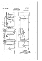
Figure 1 is a diagrammatic view of a circuit having the compensating network of the invention connected therein for modifying the electrical oscillations produced by a generator, such as of the capacitive internal reactance type, when tracking in a constant velocity sound groove on a phonograph record, such as a disk.
Figure 2.1s a diagrammatic view. of a circuit having th compensating network for reproducing a sound groove of the constant velocity form from a record for reproduction particularly over a radio broadcasting system in which a generator of the constant amplitude type is controlled by the groove.
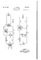
Figure 3 is a diagrammatic view of a circuit with the compensating network of the invention connected therein for driving a cutter or engraving tool controlled by a generator of the constant amplitude type forproducing a sound track upon a sound recording means such that a stylus following the track will vibrate with a constant velocity characteristic or form.
Figure 4 is a diagrammatic view of a modification of the circuit shown in Figure 1 utilizing an inductive reactance and a resistance, instead of a capacitive reactance and resistance as shown in Figure 1, and adapted to produce the same effect.
The invention to be described ,herein in one of its aspects provides for two different situations which willv be enumerated. One situation involves a circuit carrying electrical oscillations of a wide range of frequencies in which the transmission of the circuit or the amplitude of the oscillations over some portion of the range of frequencies being transmitted varies proportionately either directly or inversely with respect to frequency, and inside that portion of the range of frequencies, whether inversely or directly proportional, the transmission may be described as either linearly or substantially linearly varying. The compensating network to be described herein modifies the circuit so that the transmission of the oscillations is modified and the oscillations have an amplitude which is uniform with respect to frequency over that portion of the frequency range in which the proportional relation existed. The second situation involves a circuit carrying oscillations, the amplitude or character of which is substantially uniform with respect to frequency over some portion of the frequency range of the oscillations being transmitted. These electrical oscillations are used to drive or control a device and the effect or result could be improved by modifying the circuit so that the oscillations have an amplitude-frequency relation which is either directly or inversely proportional with respect to frequency over some portion of the frequency range of the oscillations.
It is to be understood that when the amplitude of the oscillations is stated as being proportional, either directly or inversely with respect to frequency, that proportionality may include a constant factor either positive or negative. In other words, if the amplitude-frequency relation is plotted, the linear slope if continued need not pass through the index of the graph, but may cut the X axis at any desired point in the graph.
It will be observed that each situation discussed above in turn involves two sub-divisions for consideration, namely the character of the resultant oscillations are such that the amplitude or transmission frequency relation is either directly or inversely proportional over some portion of the frequency range. The four situations for' which the simple network of the invention is applicable therefore include the correction of a circuit carrying electrical oscillations which vary directly or inversely with respect to frequency over some portion of the frequency range so that the oscillations are substantially uniform with respect to frequency over the corrected range. The network of the invention also includes the modification of a circuit carrying electrical oscillations which are substantially uniform in amplitude over the major portion of the frequency range, which oscillations are used to drive a device which should, in order to obtain a desired response, have the electrical oscillations modified so that the oscillations are directly or inversely proportional" to frequency over some portion of the frequency range.
Electrical oscillations having a wide range of frequencies may frequently have certain bands of frequencies excessively pronounced or subdued, and when either condition exists and the oscillations are either directly or inversely proportional to frequency and hence linearly varying, the circuit can'be modified by the network to be described herein. Also if a device or generator vibrated or driven by electrical oscillations does not vibrate in the manner desired, certain bands of frequencies of the oscillations controlling or driving the same may be modified in amplitude, either pronounced or subdued. The modified oscillations may be either directly or inversely proportional to frequency in order to have a desired response in the device, and such modified amplitude may be obtained with the compensating network described herein. Such electrical oscillations are frequently found in the radio and sound recording arts, as will appear more fully hereinafter.
Records for phonographs and electrical transcriptions as now manufactured have the sound track formed therein such that a stylus following the groove moves at a velocity which is constant with respect to the frequency of the vibrations recorded thereon over some portion of the frequency range. The sound groove does not have the constant velocity relation throughout its frequency range, but a predetermined portion thereof in the normal frequency working range has this constant velocity characteristic. That portion or frequency range of the groove having the constant velocity characteristic and its relative position in the frequency range, so
far as this invention is concerned, may be considered as arbitrarily determined. Commercially these two factors are determined for reasons not necesary to be considered herein.
The constant velocity form of sound-groove has an amplitude which increases with decreasing frequency and decreases with increasing frequency. The motion or oscillation of the tracking stylus and the generator vibrated thereby naturally corresponds with the character of the groove. A reproducing apparatus, such as an electro-magne'tic pick-up, is capable of translating this constant velocity form of sound track into electrical vibrations which generally only need to be amplified in order to reproduce with good fidelity the sound recorded in the groove.
1f now a type of pick-up is used on the constant velocity sound groove which is governed by some other law or characteristic inherent inthe form of pick-up used, the reproduction of the constant velocity sound track will not be accurate and after amplifying the oscillations produced by the generator and driving a speaker therewith,
amplitude responsive pick-up is found in the piezo electric crystal pickaup, in a condenser pick-up, in a stiffness controlled electro-magnetic mechanism, and certain carbon microphone types of pick-ups- The first two are the capacitive internal reactance type of generator, and the third is the inductance internal reactance type.
A piezo electric acoustic device (and also a stiffness controlled electro-magnetic type) is also used as a generator to drive an engraving or cutting tool for producing a sound groove. The sound groove produced from electrical oscillations which are uniform in amplitude over the frequency range, however, would be of a constant amplitude with respect to frequency since this is the inherent characteristic of the oscillations produced by a piezo electric generator. Such a sound groove would be unsatisfactory for use with an electro-magnetic pick-up which has a constant velocity characteristic when used without modification of the electrical oscillations generated. My compensating network is connected into the circuit to the generator so that the electrical oscillations in the circuit are modified or compensated so that the generator vibrates with a constant velocity characteristic and hence produces a sound groove having this same characteristic. Note that the groove produced is of the constant velocity form, although the generator 'is of a type which would produce a different form of groove if not compensated for with the net work of the invention.
A piezo electric crystal generator, used as a generator either for a pick-up or an engraving tool, has several advantages over the electromagnetic generator now in universal use. The principal advantage is the difference in weight between the two devices, the electro-magnetic generator being considerably heavier as compared with a piezo electric crystal generator. The lighter piezo electric, crystal generator provides a mechanism which is more responsive to high frequencies and is also less likely to damage and cause excessive wear of the record.
A piezo electric crystal pick-up, when tracking in a constant velocity sound groove, generates electrical oscillations which vary proportionately in amplitude at different frequencies so that if their amplitude is plotted with respect to frequency, the line of variation plotted will be linear throughout a considerable portion of the fre quency range, but which amplitude varies inversely with the frequency. If the electrical oscillations generated by the piezo electric crystal are amplified and operate a speaker, the reproduction of the sound track will be unsatisfactory in various respects and particularly in the lack of high frequencies or over-emphasis of the .low frequencies. I have devised, therefore, a group of networks which, when used with a piezo electric crystal pick-up, transpose, correct, or compensate the electrical oscillations generated thereby to give oscillations which are uniform in amplitude with respect to frequency, at least when the stylus is tracking through that portion of the frequency range where the sound ,groove has the constant velocity characteristic,
and transposeor compensate the electrical oscillations controlling an engraving tool so that oscillations which would otherwise vibrate the. latter with a constant amplitude. characteristic, instead control or vibrate the tool so that it engraves a sound groove having a constant velocity form or characteristic.-
A piezo electric crystal device, when used as a pick-up device, is a generator of electrical oscillations, the frequency and amplitude of the oscillations of course being determined by the sound groove. When the piezo electric crystal device is used as a cutting or engraving tool to form a sound groove, it is a generator of mechanical oscillations, the frequency and amplitude of which oscillations are controlled by the electrical oscillations applied thereto. In other words, the piezo electric crystal device is a generator of the capacitive internal reactance type, irrespective of whether it is a generator of electrical or mechanical vibrations or oscillations. Any generator is contemplated which, when its stylus is tracking in a sound groove having a constantvelocity or any other characteristic, generates electrical oscillations which are either directly or inversely proportional to frequency over at least some portion of the frequency range and, conversely, any generator is contemplated which requires electrical oscillations which are directly or inverse- 1y proportional to frequency over at least some portion of the frequency range in order to pro duce a desired form or type of mechanical vibrations of the generator, such as, for example, a constant velocity form.
A circuit is'show-n in Figure l which includes a compensatingnetwork of the invention connected with a piezo electric crystal mounted stylus iii which combination is also part of the invention. The circuit is connected with a second generator such as a vacuum tube ii. The piezo electric crystal pick-up consists principally of two crystals mounted or secured at one end and carrying a stylus at the other end for following a sound track in a record. The vacuum'tube ll illustrated is a three element tube having the usual filament l2, plate l3, and grid It. The tube may be of any suitable form or type and not necessarily a three element tube. One of the crystals of the piezo electro-acoustic device ill is connected with the grid M and the other crystal is connected with the filament of the tube through a means providing a negative bias l5. Piezo electroacoustic devices, which will be termed capacitive internal reactance generators, are known to the art and therefore further description of these devices is unnecessary. A resistance iii, in the neighborhood of two to ten megohms, is connected across the crystals of the piezo electroacoustic device.
A second vacuum tube 20 has a filament 2|, plate 22, and a grid 23. This tube is shown as a three element tube merely for the sake of illustration and any type of tube is contemplated. The compensating network is located between two generators, such as the tubes H and 20, and will now be described. The compensating network and any other form of coupling is contemplated. The plate l3 of the'tube II is connected to the grid 23 of the tube 29 through a blocking condenser 23, as known to the art, which may be about one micro-fared and is in series with a second condenser 29 which is preferably of fifty micro-micro-farads. The second condenser 29 provides the means having a reactance which is a necessary part of the compensating network. The condenser 29 is shunted by a limiting resistance 30 of the order of ten megohms. This resistance limits the decrease in transmission through the circuit for relatively low frequency oscillations caused by the condenser 29. Between the condenser 29 and the grid 23 of the vacuum tube 20 is connected a resistance 3| of the order of one-half megohm. This resistance 3| connects the grid with the filament 2| of' the tube 29 through a means providing a negative bias 32 as known to the art.
It is understood that any well known means of providing filament excitation will be added to the circuit, as determined by the types of tubes used.
In the form of circuit shown in Figure 1, the condenser 29, forming part of the compensating network or circuit, is connected in the series ciramplifying circuit shown, which tubes, so far as the invention herein is concerned, are generators of electrical oscillations. The circuit through the vacuum tubes leads to the output wires 43 and 44. The resistance 3|, on the other hand, is in a shunt circuit shunting the generator or tube 29. Where, as in the circuit illustrated in figure l, the resistance'3l also serves as a grid leak for the grid 23 of the tube 29, the value of this resistance is selected to serve its function as a grid leak and the capacitance connected in series therewith is chosen or determined upon the basis of the value of the resistance so that the resistance and the capacitance cooperate to give the proportional transmission frequency effect of the invention.
The plate 22 of the vacuum tube 20 may be connected with the primary winding of a standard transformer 35. The secondary winding of the transformer is connected with a variable resistance 36 of about two thousand ohms. This resistance is shunted by a condenser 31 and inductance 39 which are connected in series and form a series resonant circuit. The condenser 31 is of about five micro-farads capacity, and the inductance has a value of about one henry. This second network has the function of modifying the transmission frequency relation of the circuit at frequencies preferably above or below the frequency range in which the transmission frequency relation is proportional as produced by the first network and as described above, although some overlap between the effects of the two circuits is not harmful.
A compensating circuit 42 may be connected across the transformer secondary circuit formed by the wires 43 and 44. This compensating circuit may consist of an inductance 45 of twenty milli-henries in series with a condenser 46, which compensating circuit corrects for the mechanical resonance of a piezo electro-acoustic device. Mechanical resonance usually takes place between three thousand to six thousand cycles. The condenser 45 is adjusted to tune with inductance to resonate at the mechanical resonance frequency of the device ID. A standard scratch filter 41 may also be connected across the wires 43 and 44 as well as a terminator attenuating circuit 49 having the common value of flve to ten decibels.
The compensating circuit or network, forming the principal part of the invention, comprises proportional amplitude frequency characteristic occurs as controlled or determined by the condenser 29 and resistance 3|. It is desirable to increase the relative gain of the circuit in the frequency range below four-hundred cycles or thereabout. This increased relative gain may be accomplished by connecting the resistance 30 in shunt across the condenser 29. This resistance is of a value so that it has no eflect at the higher frequencies or within the range where the proportional effect occurs, but at the lower frequencies where the reactance of the condenser 29 is high, the resistance functions to stop the decrease of the relative gain or to limit the excessive variation in the circuit at the lower frequencies caused by the reactance means. The resistance, in combination with the characteristics of the piezo crystal, therefore has the effect of increasing the amplitude of the oscillations at the lower or bass frequencies so that they bear a proper ratio with respect to the higher frequencies in the reproduction. This shunt resistance has then the function of limiting the decrease in transmission at the lower frequencies caused, in the circuit shown in Figure 1, by the high-impedance of the condenser 29 at these lower frequencies.
Although the limiting resistance 30 is shown as shunting the reactance means or condenser 29, it will appear more fully hereinafter that this resistance will be connected in series with the reactance means in other circuits in order to limit the decrease in transmission caused by the impedance of the reactance means outside of a certain frequency range.
In Figure 2 the network is shown in a circuit using a piezo electrical crystal pick-up connected to a line transformer for connecting the piezo electro-acoustic device to a radio broadcasting system. In this construction the piezo electroacoustic device I0 is connected to the ends of the primary winding 50 of a transformer. The secondary winding 5| is connected with the mixer 52 of the usual radio broadcasting station. In this construction the piezo electro-acoustic device and the mixer constitute the generators between which the network of the invention is located. The compensating network connected in the circuit between the secondary winding 5| of the transformer and the mixer 52 again comprises fundamentally a reactance means 54 connected in series between two generators. A reactance means or condenser 54, having a capacity in the neighborhood of .1 micro-farad, is connected so that this condenser is in series with the resistance 53 and in series between the generators l9 and 52. The condenser 54 is shunted by a limiting resistance 63 of three thousand ohms which limits the decrease in transmission or the excessive variation in transmission at the lower frequencies below the proportional frequency transmission range in the same manner as the resistance 39 in Figure 1 performs this function.
A series resonant circuit may shunt the resistance 83 as'well as the condenser Ill and comprises a condenser 55 and an inductance 58 connected in series; :The inductance 58 is preferably in the neighborhood of two henries and the condenser 55 has a capacity in the neighborhood of three micro-farads. crease in transmission at low frequencies below the point at which linear variation begins.
The wires 60 and GI which connect the second.- ary winding ii of the transformer and the compensating network with the mixer 52 may be connected, if desired, through a mechanical resonance peak remover and a scratch filter like those shown. in Figure 1. The transformer is preferably designed to work between one-hundred thousand ohms and one -hundred to three-hundred ohms with exceedinglyhigh fidelity.
The-invention may also be utilized for compensating the vibrations or oscillations of a cutter controlled from a microphone to make the initial sound groove from which the sound groove of records are made. The circuit, including the network of the invention adapted for controlling a cutting tool. is shown in Figure 3 in which a crystal bimorph or device having a similar charto the crystal bimorph, having a transmission which varies inversely and proportionally to frequency and hence linearly over some portion of the frequency range. The production of a sound groove which will vibrate a stylus with a constant velocity is necessary in order that the well known and widely-used present day electromagnetic pick-up may continue to be used.
Referring now to Figure 3, a transformer 81 is shown which is connected with a device for translating sound vibrations into electrical vibrations or oscillations such as the usual microphone which produces electrical oscillations which are uniform with respect to frequency. The secondary winding 88 of the transformer 61 is connected with the grid or control electrode 68 of a vacuum tube 18. As previously discussed, this vacuum tube is a generator so far as this invention is concerned. A resistance ll having a value in the neighborhood of one megohm is connected in series with the grid 89 of the tube ill. The other end of-the secondary winding 68 is connected by a wire I2 to the filament 18 of the vacuum tube or generator 10. A condenser I4- is connectedin shunt with the grid circuit or with the generator 10 between resistance. II and the grid 88 and to the wire 12 so that the resistance and the condenser are in series with each other. This condenser 14 has a capacity in the Q neighborhood of .01 micro-fared.
It will be noted that in the form of the invention disclosed in Figure 3, the resistance H and condenser 14 are in series-with respect to each other, as in Figure 1, but the resistance in Figure 3 differs in its location fromthat shown in Figure 1 by being in series with the generator I0, whatever its form may be, and the reactance is in shunt with the generator.
This circuit causes an in- .form' so that a stylus carried by a pick-up of the constant velocity type will vibrate with its usual vibration to produce uniform transmission with respect to frequency over the major portion of the frequency range.
There is shown in Figure 3, therefore, a compensating network which controls the electrical oscillations in the circuit so that the oscillations decrease proportionally and hencelinearly with respect to frequency, or the oscillations are inversely proportional to the frequency of the os-' cillations over some portion of the frequency range.
A resistance 15 is provided in the shunt circuit having the condenser H and in series with the condenser in order to limit the decrease in transmission at higher frequencies which would occur'because of the relatively low impedance of the condenser 14 at these frequencies. pedance of the combined capacitance Hand the limiting resistance 15 at the frequency of maximum varying transmission may be determined from a formula to be given and. discussed hereinafter.
It should also be noted that in Figure 1 the decrease in transmission caused by the condenser The im- 28 is time lower frequencies, whereas in the cira decrease in transmission in the higher frequencies. This'change in the position of the reactance means changes the linear relation so that cuit shown in Figure 3, the condenser 14 causes the transmission varies inversely proportional to frequency over the desired range.
The plate 18 of the tube or generator III is connected to an amplifying or coupling circuit of any desirable kind, that shown being a transformer 18 which is merely illustrative of any amplifying or coupling device. This coupling circuit is connected to the crystals forming the crystal bimorph which controls the movement of a stylus or cutter which produces the initial constant velocity sound track or groove which can be subsequently reproduced by known methods using the usual constant velocity types of pick-ups, such as the electro-magnetic pick-up.
There is shown in Figure .4 a compensating network which does not utilize a condenser or capacitive reactance, but which controls the electrical oscillations in the circuit in the same manner as the network shown in Figures 1 and 2. In other words, it corrects or compensates for oscillations which are inversely proportional to frequency over some portion of the frequency range to produce uniform transmission with respect to frequency over the desired range. In this construction, the resistance 83 is connected in series with the grid or control electrode 85 of the generator or vacuum tube 84 between the tube and a crystal of a capacitive-effective reactance generator III'. The filament 86 of the vacuum tube is connected with theother element of the pick-up. A negative bias 0 is employed in a known manner. The vacuum tube or generator 84 is shunted by an inductive reactance 88 and a limiting resistance 88 in series with the reactance. The vacuum tube I4 is connected by means of the wires 90 and 9| to an output circuit of any desired form or type.
The cir uit of Figure 4 will'have the same ef-: feet as t at of the circuit shown in Figure 1. Similarly, the network arrangement of Figure 3 may be reversed by substituting for the resistive impedance ll an inductive reactance shunted by a resistance, and by replacing the condenser I4 and resistance II with a resistance determined in accordance with the formulas to be given. The decrease in transmission at high frequencies is controlled by the limiting resistance shunting the inductive reactance and having a value determined by formulas to be given hereinafter for determining a limiting resistance.
In Figure 4, it will be observed that the inductive reactance 88 provides means having a reactance which is in series with the resistance II in the series circuit between the generators. The impedance of the inductive reactance 88 controls the electrical oscillations across the resistance 83. When these impedances are determined, the transmission of electrical oscillations in the circuit varies linearly and directly proportional to frequency over some portion of the frequency range. The inverse proportion of relative transmission to frequency is obtainable by placing the inductive reactance 88 in the series circuit and the resistance 83 in the shunt circuit as taught by a comparison of the circuits of Figures 1 and 3. The limiting resistance 89 in series with the inductive reactance 8B limits the decrease in'transmission at low frequencies in the circuit, as shown in Figure 4.
The four forms of the invention disclosed herein show that the essential features of the invention include a resistance means and a reactive means connected in series and that one of these means is connected in series between two generators, and the other means is connected in shunt with one of the generators.
' pedance of the corrective network described alters the relative transmission of the electrical oscillations in the circuit to produce four major effects which, for .the lack of a better term, will be defined as a proportional effect or a propor-' tional variation.. For example, the transmission of the oscillations in a circuit to be corrected may vary proportionally, either directly or inversely, with respect to frequency over some portion of the frequency range and the desired response may require that the transmission of the oscillations beuniform or constant over this range.
The corrective network of the invention corrects the transmission be proportional, either directly or inversely, with respect to frequency over some portion of the frequency range in order to get a desired response therefrom. In such a case, the corrective network of the invention provides such proportional transmission. In some constructions the circuit to be corrected may be predominantly reactive so that the circuit can be corrected merely by the addition of resistance of a. suitable value as determined from the formulas hereinafter given, and the reactance already in the circuit cooperates therewith to produce the proportional amplitude frequency effect.
The invention in its preferred form also contemplates connecting a limiting resistance in the The im-v circuit with respect to the reactive means which limits the decrease in transmission of the circuit caused by this means. In. other words, the reactive means, whether capacitive or inductive, has an impedance which varies with the frequency of the electrical oscillations and the impedance of the capacitive reactance becomes so high at low frequencies that transmission of the low frequencies becomes negligible when the reactance is in the series circuit, and transmission of the high frequencies becomes negligible when the reactance is in the shunt circuit. Similarly, the impedance of the inductive reactance becomes so high at high frequencies that the trans- -mission through the circuit becomes excessively low in a reverse relation from that described for the capacitive reactance. A limiting resistance is provided, shunting the reactive means or in series therewith, depending upon whether it is an inductive or capacitive reactance and also depending upon whether the reactance is in the series or shunt circuit between the generators.
This resistance limits a decrease in transmission at low or high frequencies. Similarly, the impedance of the capacitive reactance in Figure 3 becomes so low at high frequencies and the impedance of the inductive reactance of Figure 4 becomes so low at low frequencies that the transmission through the circuit becomes excessively low and the resistances 15 and 88 are provided to limit this decrease in transmission.
It will now be pointed out that it is not necessary to have the resistance means and the reactance means connected directly in series and there may be various electrical transmitting devices therebetween, such as a transformer, so long as those devices are not of a blocking type, such as a vacuum tube or a terminator attenuating circuit.
I prefer to design my circuit according to the following method, which does not pretend to be of the highest scientific accuracy. However, it is much simpler and shorter than a highly rigorous method would be, and yields results which are entirely satisfactory within the usual practical limits of the art.
1. Determine generator impedances. These should be predominantly resistive. However, if one generator is predominantly reactive, the other generator should be predominantly resistive, or if it is reactive, then it must be of the same character as the first generator. Where one generator is reactive and the other resistive. the proportion of resistance and reactance should be such that the circuit power factor is as high as possible considering only the two generators. Also, in that case a series type of corrective cirsuit should be used in most applications. For example, in correcting the characteristics of a crystal phonograph pick-up, a series, condenser type of circuit is used which presents a very high impedance to the pick-up at the low frequencies, where the pick-up impedance is great enough to require consideration. This is because the pick-up impedance is capacitive. Thereby the reactive character of the pick-up produces no practical effect and can be ignored thereafter in the calculations. Note also that a transformer may be used to change a generator im pedance as presented to the equalizer.
2. Determine response-frequency characteristics of the generator requiring correction. The generator requiring correction need not be one of those between which the corrective network is positioned. In other words, how much linl6 early varying transmission in decibels is needed and where is it to be positioned in the frequencyl spectrum. I am particularly interested in the frequency of maximum linearly varying 4. Decide on what type of equalizer circuit to use. To a. great extent this involves a knowledge of network art. If both generators are resistive in character, pick an equalizer circuit using a condenser in preference to one using an inductance, even though both do the same work. The reason, of course, is that the condenser method is cheaper. In addition, sometimes the inductance found by methods given in succeeding paragraphs is unrealized, for example, due to the distributed capacity being excessive.
Occasionally one of the generators is reactive in character within the working frequency range. Then, as noted inthe procedure step 1 above, a circuit configuration is selected (and the other generator impedance where this is possible) which will make the reactive generators reactance of minimum or no practical effect. If a generators impedance cannot be directly changed, it may be changed in effect by interposing a transformer. For example, again, in designing a crystal pick-up equalizer, the pick-up reactance maybe very great as compared to the other generator, if the latter is a broadcast station mixer. A transformer, however, steps up the mixers" 200 ohms resistance to the desired value to present to the equalizer and the pick-up.
As another example of this procedure, in using a crystal phonograph record cutter, the reactance of the latter may be used as a portion of the equalizer circuit. It is usually ill adapted, however, to cooperate in an eflicient way with the amplifier circuit feeding it. Therefore, the crystal reactance maybe stepped down to amore desirable value witha transformer, as shown elsewhere in my disclosure.
5. Determine the value of the limiting resistance to be used as follows:
A. Series corrective circuit.
L RIM... (z.+z )[(1oga 1] B. Shunt corrective circui1;
Z1=impedance of the input generator, and
Zz=impedance of the output generator.
Use the formula for the circuit previously chosen. For most accurate results it is best to use (L-r+ /2) in place of Dr in the above formula.
- 6. Find the frequency of maximum varying transmission. Use formula:
K= 1.7+.0456L.where L, is in D. B.
Then when transmission of corrective circuit increases with increasing frequency:
Frequency of maximum varying transmission =h frequency of max! mum linearly varying transmission.
Or, when transmission of corrective circuit decreases as frequency increases:
frequency 'of maximum linearly varying trans- Frequency. of maximum} mission varying transmission K 7. Next, calculate Z. the impedance of the combination of the reactance X (of the reactive branch) and its associated limiting resistance R. as connected in either type of circuit, at the frequency of maximum varying transmission.
Choice of condenser or inductance Series circuit:
Input 21 Output 21 The corrective circuit sketched above may be described as having the condenser or inductance X in series with the input and output circuits or in series with the generators. In this corrective circuit. the limiting resistance R shunts'X. R may be found from formulas previously given.
Where Z1==impedance of input circuit (assumed resistive) Zz=impedance of output circuit (assumed resistive) Z =impedance of combination of X and R at frequency of maximum varying transmission, and g =phase angle of Z at above frequency.
Because cannot be known until Z is calculated,
first assume cos =.04 and calculate Z. Then cos may be calculated from well known electrical principles. Then again calculate Z.
Shunt circuit:
Input Zr x A Output 2:
The circuit sketched above may be described as having the condenser or inductance X shunted across input and output circuits or the generators, with the limiting resistance R in series with the inductance. B is determined from previously given formulas.
Where Ro=Z1=Zz that is, input and output are assumed equal, and resistive.
Z =impedance of combination of X and R. at frequency of maximum varying transmission =phase angle of Z at above frequency.
Since 4 cannot be knownexactly u'ntil Z is known, exactly the same two-step procedure must be used as for series equalizer circuit, assuming cos =.04 for the first trial. Then recalculate Z. Formulafor Z is on basis of transmission less their maximum in each case.
8. Calculate X, the reactance of the reactive arm at the frequency of maximum varying transmission previously determined. This is done because either of the following circuits has been previously chosen:
R with R, the limiting resistance, known from previous steps, and Z the impedance of the combination also previously determined. This solution is well known and reference may be had to any good book on alternating current theory for the basic formula and idea, such as:
Principles of Alternating Currents, R. R. rance, McGraw Hill Book Co., 1922.
Handbook for Electrical Engineers, Harold Pender, John Wiley & Sons, second edition revised-page 22.
Radio Engineering Handbook, Keith Henney, McGraw Hill Book Co., 1935 edition, section 6.
9. The value of X found directly above; and the frequency of maximum varying transmission, I, found previously, may now be used' to calculate the value of L or C to be used in a first trial of the equalizer.
Law-
10 2wfX Where)! is in ohms I is in cycles per second L is in henries C is in micro-farads.
10. The value so found is invariably close enough so that it causes no practical difflculty. It is then best to set up such a circuit, as calculated, using commercial adjustable resistances and condensers. Invariably it is found that practical experience dictates slight modifications, chiefly because of unavoidable errors in determining the characteristics in the original test or because slight deviations from linear variation in the device to be corrected exist due to driving mechanism, mechanical' impedance, etc. A slight change and retest usually make the best compromise consistent with commercial conditions and the design is then complete.
Various modifications will occur to those skilled in the art in the configuration, composition and disposition of the component elements going to make up the invention as a whole, as well as in the selective combination or application of the respective elements, and no limitation is intended by the phraseology of the foregoing description or illustrations in the accompanying drawings, except as indicated in the appended claims.
What is claimed is:
'1. A circuit having or requiring variation in oscillation strength or requiring a correcting variation," each of which variations is linearly proportional with respect to frequency over some portion of the frequency range comprising an input generator, and an output generator, one of the generators having a reactance which varies proportionally and linearly with respect to frequency over some portion of its frequency range and the other having a resistive character, the resistive generator having a value of resistance so that the transmission of the oscillations in the circuit is corrected in a linearly varying manner in that portion of the frequency range where the aforesaid linearly proportional variation with respect to frequency would normally occur.
2. A circuit having or requiring variation in oscillation strength or requiring correcting variation, each of which variations is linearly proportional with respect to frequency over some portion of the frequency range comprising an inresistance means connected within the circuit :0
and its value of resistance chosen so that the transmission of the oscillations in the circuit is corrected in a linearly varying manner in that portion of the frequency range where the aforesaid linearly proportional variation with respect to frequency would normally occur.
3. A circuit having or requiring variation in oscillation strength or requiring a correcting variation, each of which variations is linearly proportional with respect to frequency over some portion of the frequency range comprising an input generator, an output generator a series connection between the generators, a shunt connection, a resistance forming the sole element of one of said connections and its value of resistance chosen so that the transmission of the oscillations in the circuit is corrected in a linearly varying manner with respect to frequency over some portion of the frequency range, and a reactance means in the other connection which has a reactance which varies linearly with respect to frequency over the desired frequency range and is connected in series with the resistance, the reactance means having a value with respect to the resistance so that transmission of the oscillations in the circuit has a linearly proportional effect with respect to frequency over the aforesaid portion of the frequency range.
4. A corrective network to be connected in a circuit connecting two generators for introducing a linear and proportional correction, or in order for, or convert uniformly transmitted oscillations into, oscillations which vary proportionately with respect to frequency over some portion of the frequency range comprising a series connection adapted to be used between the generators,
a shunt connection, a resistance forming the sole element in one of said connections and its value chosen with respect to the impedance of the generators and the total transmission variation so that the transmission of the oscillations in the circuit is corrected in a linearly varying manner with respect to frequency over the aforesaid portion of the frequency range, and a reactance means, the reactance of which varies linearly and proportionally with respect to frequency over the desired frequency range, the reactance means being connected'in the circuit in series with. the resistance and in the other connection between the generators, the reactance means having a value of reactance such that the linearly proportional effect of the transmission of the oscillations is at the desired range of frequency of the oscillations.
5. A corrective network to be connected in a 1 circuit connecting two generators for introducforming the sole element connected in series between the generators and its value of resistance chosen with respectto the impedances of the generators and the total transmissionvariation so that the transmission of the oscillations in the circuit is corrected in a linearly varying manner with respect to frequency over the aforesaid portion of the frequency range, and a series resonance peak remover connected in shunt between the generators'and at any point with respect to the resistance and having a value of transmission loss such as to substantially annul the effect of a resonance peak in one or both of the gen erators.
6. A corrective network to be connected in a circuit connecting'two generators for introducing a linear and proportional correction, or in order to correct for, or convert uniformly transmitted oscillations intooscillations, the transmission of which will vary proportionately and linearly with respect to frequency over some portion of the frequency range comprising a series connection between the generators, a shunt connection, a resistance forming the sole element of one of said connections depending uponthe result desired and its value of resistance determined with respect to the impedances of the generators and the total transmission variation so that the transmission of the oscillations in the tion of the frequency range, and a reactance.
means connected in the other connection and having a value of reactance such that the linearly proportional effect of the transmission of the oscillations is at the desired range of frequency of the oscillations, and a resistance means connected with respect to the reactance means to limit the decrease in transmission caused thereby. f
7. A'corrective network to be connected in a circuit connecting two generators for introducing a linear and proportional correction, or in order to correct for, or convert uniformly transmitted oscillations into oscillations, the transmission of which vary proportionately and linearly with respect to frequency over some portion of the frequency range comprising a series connection between the generators, a shunt connection, a resistance forming the sole element of one of said connections and its value of resistance chosen with respect to the resistance of the generators and the total transmission variation so that the to limit the excessive variation in transmission caused thereby. I
8. An electro-acoustic device adapted to cut or reproduce a sound groove comprising a generator for cutting or reproducing a sound track which generator produces or requires oscillations which vary linearly and proportionally with respect to frequency over some portion of the frequency range, a second generator, and a circuit connecting the two generators which circuit is one of two connections including a series circuit and a series and shunt circuit forming a compensating network, a resistance forming the sole element in one of the connections and the value of which is chosen so that the transmission of the oscillations in the circuit is corrected in a linearly varying manner with respect to frequency over the aforesaid'portion of the frequency range.
9. An electro-acoustic device adapted to cut or reproduce a sound groove comprising a generator for cutting or reproducing asound track which generator produces or requires oscillations which vary linearly and proportionally with respect to frequency over some portion of the frequency range, a second generator, and a circuit connecting the two generators including a series connection and a shunt connection, a resistance forming the sole element of one of said connections between the generators and the value of which is chosen so that the transmission of the oscillations in the circuit is corrected in a linearly varying manner with respect to frequency over some portion of the frequency range, and a reactance means connected in series with the resistance and in the other connection between the gener-' ators and its value chosen such that the linearly proportional effect of the transmission of the oscillations is over the desired range of frequencies.
10. An electro-acoustic device adapted to cut or reproduce a sound groove comprising a generator for cutting or reproducing a sound track which generator produces or requires oscillations which vary linearly and proportionally with respect to frequency over some portion of the frequency range, a second generator, and a circuit connecting the two generators including a series ner with respect to frequency over some portion of the frequency range, a reactance means con-v nected in series with the resistance means and in the other connection between the generators and its value chosen such that the linearly proportional effect of the transmission of the oscillations is over the desired range of frequencies, and a resistance connected with respect to the reactance means to limit the excessive variation in transmission caused thereby.
11, An electro-acoustic device adapted to cut or reproduce a sound groove of the constant velocity form comprising a piezo crystal generator for cutting or reproducing a sound track which generatorproduces or requires oscillations which vary linearly and proportionally with respect to frequency over some portion of the frequency range, a second generator, and a cir- Y cuit is corrected in a linearly varying manner with respect to frequency over the aforesaid portion of the frequency range and forming the sole element in one of the positions of shunt and series connection with respect to the generators.
12. An electro-acoustic device adapted to cut or reproduce a sound groove of the constant velocity form comprising a piezo crystal generator for cutting or reproducing a sound track which generator .produces or requires oscillations which vary linearly and proportionally with respect to .frequency over some portion of the frequency range, a second generator, and a circuit connecting the two generators including a series connection and a shunt connection, a resistance forming the sole element of one of said connections and the value of which is chosen so that the transmission of the oscillations in the circuit is corrected in a linearly varying manner with respect to frequency over the aforesaid portion of the frequency range, and a reactance means connected in the circuit and in the other position in the circuit.
13. An electro-acoustic device adapted to cut or reproduce a sound groove of the constant velocity form comprising a piezo crystal generator for cutting or reproducing a sound track which generator produces or requires oscillations which vary linearly and proportionally with respect to frequency over some portion of the frequency range, a second generator, and a circuit connecting the two generators including a series connection and a shunt connection, a resistance forming the sole element of one of said connections and the value of which is chosen so that the transmission of the oscillations in the circuit is corrected in a linearly varying manner with respect to frequency over the aforesaid portion of the frequency range, and a reactance means connected in series with the resistance means and in theother connection of the circuit.
14. An electro-acoustic device adapted to cut or reproduce a sound groove of the constant velocity form comprising a piezo crystal generator for cutting or reproducing a sound track which generator produces or requires oscillations which vary linearly and proportionally with respect to frequency over some portion of the frequency range, a second generator, and a cirand a series resonant means connected in the shunt connection in the circuit and in any desired relation with respect to the resistance means.
15.An electro-acoustic device adapted to cut or reproduce a sound groove of the constant velocity form comprising a piezo crystal generator for cutting or reproducing a sound track which generator produces or requires oscillations which vary linearly and proportionally with respect to frequency over some portion of the frequency range, a second generator, and a circuit connecting the two generators including a series connection and a shunt connection, a resistance forming the sole element of one of said connections and the value of which is chosen so that the transmission of the oscillations in the circuit is corrected in a linearly varying manner with respect to frequency over the aforesaid portion of the frequency range, a reactance means connected in series with the resistance means and in the other connection in the circuit,
and a resistance connected in the connection with the reactance means and in relation thereto to limit the decrease in transmission caused thereby.
16. An electro-acoustic device adapted to cut or reproduce a sound groove of the constant velocity form comprising a piezo crystal generator for cutting or reproducing a sound track which generator produces or requires oscillations which vary linearly and proportionally with respect to frequency over some portion of the frequency range, a second generator, and a circuit connecting the two generators including a' series connection and a shunt connection, a resistance forming the sole element of one of said connections and the value of which is chosen so that the transmission of the oscillations in the circuit is corrected in a linearly varying manner with respect to frequency over the aforesaid portion of the frequency range, and a reactance means connected in series with the resistance means and in the other connection in the circu 1'7. A circuit having or requiring variation in oscillation strength or requiring a linear and proportional correcting variation, each of which variations is proportional with respect to frequency over some portion of the frequency range, comprising an input generator, an output generator, a resistance means connected within the circuit, and a reactance means in series with the resistance means, the value of resistance in the circuit including the generators being determined by one of the formulas so that transmission of the oscillations in the circuit is corrected in a linearly varying manner with respect to frequency over some portion of the frequency range.
18. A circuit utilizing a series corrective network having or requiring variation in oscillation strength or requiring a linear and proportional correcting variation, each of which variations is proportional with respect to frequency over some portion of the frequency range comprising an input generator, an output generator, a' resistance means connected within the circuit, and a reand actance means in series with the resistancemeans, a limiting resistance connected with respect to the reactance means to limit the attenuation caused thereby, the value of limiting resistance in the circuit being determined from the so that transmission of the oscillations in the circuit is corrected in a linearly varying manner with respect to frequency over some portion of the frequency range.
19. A circuit utilizing a shunt corrective network having or requiring variation in oscillation strength or requiring a linear and proportional correcting variation, each of which variations is proportional with respect to frequency over some portion of the frequency range comprising an input generator, an output generator, a resistance means connected within the circuit, and a reamazes actance means in series with the resistance means. a limiting resistance connected with respect to the reactance means to limit the attenuation caused thereby, the value of limiting resistance in the circuit being determined from the formula work connected with the generator for coaotion therewith, the compensating network including one of the two connections namely a series connection and-a series and shunt connection, and a resistance means forming one connection and the value of the resistance is chosen so that the transmission of the oscillations in the circuit is corrected in a linearly varying manner with respect to frequency over the aforesaid portion of the frequency range.
21. An electro-acoustic device adapted to cut or reproduce a sound groove comprising a gen.- erator for cutting or reproducing a sound track which generator produces or requires oscillations which vary linearly and proportionally with respect to frequency over some portion of thefrequency range, and a compensating network connected with the generator for coaction therewith including a series connection and a shunt connection, a resistance means forming one of said connections and the value of'the resistance is chosen so that the transmission of the osciilations in the circuit is corrected in a linearly varying manner with respect to frequency over some portion of the frequency range, and a reactance means connected in series with the resistance means and in the other connection and its value of reactance chosen such that the linearly proportional eflect of the transmission of the oscillations is over the desired range of frequencies.
22. An electro-acoustic device adapted to cut or reproduce a sound groove comprising a generator for cutting or reproducing a sound track which generator produces or requires oscillations which vary linearly and proportionally with respect to frequency over some portion of the frequency range, and a compensating network con-' nected with the generator for coaction therewith including a series connection and a shunt connection. 'a resistance means forming one of the connections and the value of the resistance is chosen so that the transmission of the oscillations in the circuit is corrected in a linearly varying manner with respect to frequency over some portion of the frequency range, a reactance means connected in series with the resistance.
means and in the other connection and its value of reactance chosen such that the linearly proportional effect of the transmission of the oscillations is over the desired range of frequencies, and a resistance connected with respect to the reactance means to limit the variation in transmission caused thereby.
CLARENCE J. LE BEL.
Priority Applications (1)
| Application Number | Priority Date | Filing Date | Title |
|---|---|---|---|
| US157142A US2218399A (en) | 1937-08-03 | 1937-08-03 | Compensating network |
Applications Claiming Priority (1)
| Application Number | Priority Date | Filing Date | Title |
|---|---|---|---|
| US157142A US2218399A (en) | 1937-08-03 | 1937-08-03 | Compensating network |
Publications (1)
| Publication Number | Publication Date |
|---|---|
| US2218399A true US2218399A (en) | 1940-10-15 |
Family
ID=22562495
Family Applications (1)
| Application Number | Title | Priority Date | Filing Date |
|---|---|---|---|
| US157142A Expired - Lifetime US2218399A (en) | 1937-08-03 | 1937-08-03 | Compensating network |
Country Status (1)
| Country | Link |
|---|---|
| US (1) | US2218399A (en) |
Cited By (6)
| Publication number | Priority date | Publication date | Assignee | Title |
|---|---|---|---|---|
| US2451613A (en) * | 1944-08-02 | 1948-10-19 | Remington Arms Co Inc | Electrical conductivity testing machine |
| US2480052A (en) * | 1943-02-03 | 1949-08-23 | Hartford Nat Bank & Trust Co | Combined filter network and electromechanical transducer |
| US2541393A (en) * | 1947-01-22 | 1951-02-13 | Wilcox Gay Corp | Crystal cutter driving circuit |
| US2657276A (en) * | 1949-12-22 | 1953-10-27 | Stromberg Carlson Co | Method and means for obtaining a predetermined phase shift characteristic |
| US4199730A (en) * | 1949-09-28 | 1980-04-22 | The United States Of America As Represented By The Secretary Of The Army | Double peaked amplifier |
| US4622660A (en) * | 1983-02-17 | 1986-11-11 | Cowans Kenneth W | Systems and methods for signal compensation |
-
1937
- 1937-08-03 US US157142A patent/US2218399A/en not_active Expired - Lifetime
Cited By (6)
| Publication number | Priority date | Publication date | Assignee | Title |
|---|---|---|---|---|
| US2480052A (en) * | 1943-02-03 | 1949-08-23 | Hartford Nat Bank & Trust Co | Combined filter network and electromechanical transducer |
| US2451613A (en) * | 1944-08-02 | 1948-10-19 | Remington Arms Co Inc | Electrical conductivity testing machine |
| US2541393A (en) * | 1947-01-22 | 1951-02-13 | Wilcox Gay Corp | Crystal cutter driving circuit |
| US4199730A (en) * | 1949-09-28 | 1980-04-22 | The United States Of America As Represented By The Secretary Of The Army | Double peaked amplifier |
| US2657276A (en) * | 1949-12-22 | 1953-10-27 | Stromberg Carlson Co | Method and means for obtaining a predetermined phase shift characteristic |
| US4622660A (en) * | 1983-02-17 | 1986-11-11 | Cowans Kenneth W | Systems and methods for signal compensation |
Similar Documents
| Publication | Publication Date | Title |
|---|---|---|
| US2173427A (en) | Electric oscillator | |
| US2434155A (en) | Electronically controlled variable gain amplifier | |
| US2218399A (en) | Compensating network | |
| US1689339A (en) | Energy-translation system | |
| US2282383A (en) | Audio frequency amplifier | |
| US2282381A (en) | Amplifier | |
| US2245652A (en) | Method of and apparatus for the reproduction of sound | |
| US2205190A (en) | Oscillation generator | |
| US2491244A (en) | Signal receiving and transmitting apparatus | |
| US2358630A (en) | Amplification system | |
| US1478078A (en) | Equalizing network | |
| US2456992A (en) | Frequency shift keying plus phase modulation | |
| US2286437A (en) | Piezoelectric temperature compensating circuit | |
| US1569411A (en) | Dynamic transmitter | |
| US2323392A (en) | Electrical musical instrument | |
| US1928410A (en) | Sound reproducing system | |
| US2157880A (en) | Recording system | |
| US2118602A (en) | Phonograph with automatically compensated tone and volume control | |
| US2866856A (en) | Controlled oscillator systems | |
| US2800586A (en) | Artificial inductor | |
| US1687933A (en) | Electrical signaling system | |
| US2349888A (en) | Sound recording system | |
| US1713039A (en) | Phonograph recording and reproducing | |
| US1725954A (en) | Amplifier | |
| US2480052A (en) | Combined filter network and electromechanical transducer |