US2206492A - Spline shaft grinding machine - Google Patents
Spline shaft grinding machine Download PDFInfo
- Publication number
- US2206492A US2206492A US271302A US27130239A US2206492A US 2206492 A US2206492 A US 2206492A US 271302 A US271302 A US 271302A US 27130239 A US27130239 A US 27130239A US 2206492 A US2206492 A US 2206492A
- Authority
- US
- United States
- Prior art keywords
- piston
- passages
- conduit
- index
- passage
- Prior art date
- Legal status (The legal status is an assumption and is not a legal conclusion. Google has not performed a legal analysis and makes no representation as to the accuracy of the status listed.)
- Expired - Lifetime
Links
- 238000000227 grinding Methods 0.000 title description 21
- 230000007246 mechanism Effects 0.000 description 51
- 230000001276 controlling effect Effects 0.000 description 8
- 230000009471 action Effects 0.000 description 4
- 230000002093 peripheral effect Effects 0.000 description 4
- 238000006073 displacement reaction Methods 0.000 description 2
- 239000007788 liquid Substances 0.000 description 2
- 230000008901 benefit Effects 0.000 description 1
- 230000007547 defect Effects 0.000 description 1
- 238000010586 diagram Methods 0.000 description 1
- 238000003754 machining Methods 0.000 description 1
- 238000003801 milling Methods 0.000 description 1
- 238000012986 modification Methods 0.000 description 1
- 230000004048 modification Effects 0.000 description 1
- 230000001105 regulatory effect Effects 0.000 description 1
- 230000000284 resting effect Effects 0.000 description 1
Images


Classifications
-
- B—PERFORMING OPERATIONS; TRANSPORTING
- B24—GRINDING; POLISHING
- B24B—MACHINES, DEVICES, OR PROCESSES FOR GRINDING OR POLISHING; DRESSING OR CONDITIONING OF ABRADING SURFACES; FEEDING OF GRINDING, POLISHING, OR LAPPING AGENTS
- B24B19/00—Single-purpose machines or devices for particular grinding operations not covered by any other main group
- B24B19/02—Single-purpose machines or devices for particular grinding operations not covered by any other main group for grinding grooves, e.g. on shafts, in casings, in tubes, homokinetic joint elements
Definitions
- Our invention relates to automatic machine tools for grinding splinedshafts, cutting the teeth of gear wheels, and the like, and producing in general circumferentially profiled pieces of work, of which the blanks in the course of the machining operations are axially reciprocated relatively to the tool, and are step by step angularly indexed relatively to the tool.
- the invention relates more especially to improvements in automatic machine tools of the type and for the purposes set forth hereinafter briefly called spline shaft grinding machines, in which the said reciprocating and indexing movements are both performed by hydraulically operated mechanisms.
- Spline shaft grinding machines having hydraulically operated mechanisms for performing the reciprocating and indexing movements concerned are nowadays preferred in many cases, because-their hydraulic mechanisms are capable of being more easily controlled by the operator, namely, readjusted in a continuous and highly exact manner as to their working speed, for
- the principal object of this invention is to provide an improved hydraulically operated spline shaft grinding machine of the type'concerned, in which the mechanism for reciprocating the 40 blank relatively to the tool is cooperatively associated with and functionally subordinated to the indexing mechanism in such manner, that the reciprocating mechanism is not unlocked and set free for starting upon a fresh working stroke until the indexing mechanism has been properly re-set and locked in its fresh working position.
- the invention aims at avoiding damaging the workpiece of the machine tool or both in the event of the hydraulically actuated indexing mechanism not operating accurately on account of leakage in the conduits, namely at positively preventing the table to start upon a instance as to the feeding of the blank relatively the control elements and to reduce the wear of the delicate parts of the indexing mechanism for the purpose of facilitating their smooth operation and ensuring gentle and highly accurate indexing operations.
- the invention aims at reducing the number of the component parts of the indexing mechanism, especially the number of liquid conduits, so as to reduce the sources of defects.
- the invention aims at providing improved means for regulating the speed in the indexing operationsincluding turning of the index plate, and engagement of the pawl-so as to afford coarse indexing to be performed as quickly as fine indexing.
- Fig. 1 is a. fragmentary front elevation showing the re-designed machine with its most important parts
- Figs. 2 and 2a are electric wiring diagrams showingthe main pawl of the indexing mecha- 6 nism in different positions
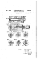
- Fig. 3 shows the indexing mechanism on a larger scale and in section vertically taken through its main axis
- Fig. 3a is a cross-section of the indexing mech- 35 anism taken on line IIIa-IIIa of Fig. 3,
- Fig. 4 is a front elevation of-,the indexing mechanism with casing cover removed
- Figs. 5 and 5a show in section taken on line V--V of Fig. 4 a time-relay provided in the in- 40 dexing mechanism and its hydraulic motors for the index pawl and for the index plate in differ. ent operating positions
- Fig. 6 is a section vertically taken through the table and indexing control mechanism on line 45
- Fig. 7 is a section horizontally taken through the principal oscillatable control member on line VI[VII of Fig. 6; Y
- Fig. 8 shows some partsiof the control member 50 shown in Fig.6 in section
- Fig. 9 is a cross section vertically taken through the principal control member on line IX-IX of Fig. 6 and showing also an electromagnetically operated shut off valve associated therewith; 5'5
- Figs. 10 to 15 are cross sections through the I principal control member taken on lines XX to XVXV of Fig. 6;
- Fig. 16 is a diagrammatic general view of a machine modified structurally, wherein the reciprocating table carries the grinding wheel, whereas the indexing mechanism and the workpiece are stationary.
- the spline shaft grinding machine re-designed with the objects in view outlined above comprises:
- i and the indexing mechanism 22 are both operated by hydraulic pressure produced by an oil pump 26 driven by a prime mover M (Figs. 2, 2a) the oil is sucked from storage tank 3
- the oil conduit 20 divides into several branches within a control block 40, allowing the oil to pass from the conduit 29 through a throttle valve 19 (Fig. 6) operable by hand into two passages and 9
- the shut-off valve 31 (Figs. 1, 9) has a longitudinal channel 36 and an annular recess I04 and isconnected to an electromagnet I03; conduit 39 leads from valve 31 to a cock plug 4
- and 42 (Figs. 6, 'l and 81 are arranged coaxially in a bore hole of the control block 40; they are rigidly interconnected by a spline shaft 43; a sleeve 44 is slidably arranged on said spline shaft 43 between said cock plugs and participates in their rotary motion.
- has a circumferential groove 93 (Fig. 9) and a longitudinal groove 56 (Figs. 6 and 8),
- cock plug 42 has two peripheral passages 94 and (Figs. 7, 14, 15) and a longitudinal passage 55, whereas the sleeve 44 has two peripheral recesses 48 and 52.
- and 42 are turned around jointly with the sleeve 44 by means of an adjustable dog or abutment 46 (Fig. 1) fixed on the table 2
- and 62 (Fig. 6) in the control block 40 are connected with a discharge passage 54, a spring loaded pressure ball valve .99 being arranged in the discharge of the passages 6
- control block 40 has passages 49, 59 (Fig. 7) which unite to form a passage 91 leading to the right sid of the piston 50 operating the table 2
- the indexing mechanism 22 comprises an index plate (Figs. 3 and 4) which is exchangeably mounted on the workpiece spindle 92 and in which an oscillatably mounted index pawl 9
- Keyed on the workpiece spindle 92 is a ratchet wheel 96 in which a pawl engages which is mounted on a toothed wheel 94 and kept constantly in contact with the ratchet wheel 99 r by a spring not shown on the drawings.
- a rack 93 (Fig. 3a) movable perpendicular to the plane of the drawings meshes with the toothed wheel 94 and is arranged on and coaxial to the piston of a hydraulic motor I00 (Figs. 3a and 5).
- (Fig. 4) is a two-armed lever which is mounted on a bolt I02 (Fig. 4) and has on the end of one arm a nose 91 engaging the notches in the index plate and on the end of the other arm a contact plate 99 which is pressed constantly'against a contact 92 of a two-wire electric cable 69 for the electric magnet I03 (Fig. 9).
- the cable 69 has a second contact 18 (Fig. 2) which, when the index pawl 9
- is continually pressed strongly against the index plate 90 by a spring I21 (Fig. 4).
- is operated by a hydraulic motor, the piston IOI of which (Figs. 4, 5) has annular passages H6 and H1 and is connected to an extension of the pawl 9
- Passages H3 and I are formed in the indexing mechanism which are connected to the conduit 64' referred to above (Figs. 1 and 5).
- are cooperatively interconnected bypassages II5, 20 and I24; the piston IOI is in turn connected by conduits I2
- 2I and its extension V lead to the front side (Figs. 3a and 5) of the piston I00 operating the index plate 90, while the passage I23 and its continuation H lead to the rear side of said piston I00.
- passages I09, I09, II9, I22, I25 are connected to an overflow conduit II9 which leads to an oil collecting tank I26.
- the electric equipment comprises (1) a main,
- the table control the Working piston 58 (Fig. 1), and forces the latter towards the left.
- the oil on the left side of the piston 58 fiows back to the collecting tank through the conduits 88, 5
- Pressure oil also passes from the conduit 28 through the passages 33, 34, to the right side of the sleeve 44, the left side of which is connected to the discharge passage 54 by the passages 56, 51, so that the sleeve 44 is maintained in its extreme'left position by the liquid pressure.
- the tool may be mounted on the reciprocating table, while the work piece and the indexing mechanism are stationarily fixed as seen in Fig. 16 of the drawings:
- the indexing mechanism 22' is secured to the machine bed 20' by screw bolts 1', 2', while the support 24' of the grinding wheel 24" is fixed at e, e' and carried by the reciprocating table 2
- the pressure oil conduit 84" can be made in the form of an ordinary pipe rigidly connecting the indexing mechanism with the control block 40', while in the machine shown in Fig. 1 a telescope or other extensible tube 94' and a flexible cable 69 following the reciprocating movements of the indexing mechanism must be provided.
- said reciprocating mechanism comprising a piston attached to said table and means for alternately distributing oil under pressure to opposite sides of said piston
- said controlling means comprising a shut-off valve and an electromagnet operating the latter and cooperatively associating the said indexing mechanism and distributing means, the latter comprising a rotary spline shaft adapted to be revolvingly reciprocated by the table, a pair of recessed cock plugs coaxially fixed on said spline shaft, and a recessed sleeve slidably fixed on said spline shaft between said cock plugs for cooperation with the latter.
- a machine tool having a tool and a table adapted to be reciprocated relatively to each other in rectilinear paths of movement
- said indexing mechanism comprising a circumferentially notched index plate, an index pawl adapted to engage the notches 0!
- said plate a ratchet mechanism en- .,gagingthesaidheadstockspindleandintum revolving said index plate, a piston tor actuating said ratchet mechanism, another piston for actuating said index pawl, and a time-relay for controlling the admission ofoil under pressure to said pistons
- said index pawl comprisinga double armed lever loaded by a spring, acircuit making and breaking plate for cooperation with said controlling means, and a bell crank lever interengaging said lever and the piston actuating the index pawl.
- said indexing mechanism comprising a circumferentially notched index plate, an index pawl adapted to engage the notches of said plate, a ratchet mechanism engaging the said headstock spindle and in turn revolving said index plate, a piston for actuating said ratchet mechanism, another piston for actuating said index pawl, and a time-relay for controlling the admission of oil under pressure p to said pistons, said time-relay comprising a
Landscapes
- Engineering & Computer Science (AREA)
- Mechanical Engineering (AREA)
- Machine Tool Units (AREA)
Description
July 2 1940. R. WESTENBERGER ET AL SPLINE SHAFT GRINDING uAcn'nlE Filed May 2, 1939 '7 Sheets-She'et -1' Fig-.
Inventors: Rudolf 9103601050 ,0 1. U0 wn H u. m mw fave/5 Attorney.
July 2, 1940. R. WESTENBER GER ET AL 2 SPLINE SHAFT GRINDING MAQHIIIE Filed May 2, 19:59 7 Sheets-Sheet 2 Fig.3
7nuen/ors: Ruao/fh/es/enbcrger h/a/ler Haqff Willy 689,91, WM m6 Al/omey July 2, 1940. R. WESTENBERGER tr AL 2.0. 3
SPLINE SHAFT GRINDING MACHIIE Filed May 2, 1939 I 'T Sheets-Sheet 3 I"In!llllllllllllJl/llll[I'll/111111111111 Jnwenfon: Rudolf mumm Wall!!- Hquffo Willy awgi Attomoy.
July 2. 1940 R. WESTENBERGER Er AL' 2,205,492
SPL-INE SHAFT emm'ame MACHINE Filed May 2, 1939 '7 She etS-Sheet 4" Jnnnfofd': Rudd} Wutmbergir Walter Hauffc Willy Georg M Attorney.
July 2,1940. R. WESTENBERGER El AL 3 SPLINE SHAFT GRINDING MACHI'E Fned May 2-, 19:59 7 Shets-Sheet s Fig. 5
IIImInfOI-J Rudolf wastcnbergcr Walter Hqujfa Willy Georgi ARM-My July 2, 1940. R. WESTENBERGER IEI' AL 2,205,492
SPLINE SHAFT GRINDING MACHINE 7 Sh eets-Sheet'6 Filed May 2, 1939 Inventors: Rudolf Wutcnberger Waller Haufio wi Georgi I 2, 9 R. WESTENBERGER ET AL 2,206,492
SPLINE SHAFT GRINDING MACHINE Filed May 2, 1959 7 Sheets-Sheet 7 5 L 5 0 v3 5 a I ll. 1 I JIM!" I C My I m V 7 5' 7 v H 0w 1 I 9 4 H inventor-$1 Rudolf Wufgnbe rgcr mm mm WM Ma Atformy Patented July 2, 1940 UNITED STAT-ES 2,205,492 SPLINE smr'r oanmme MACHINE Rudolf Westenberger, Walter Hauife, and Willy Georgi, Chemnitz, Germany, assignors to J. E. Reinecker, Aktien-Gesellschaft, Chemnitz, Germany Application May 2, 1939, Serial No. 271,302 In Germany November 30, 1932 4 Claims. (01. 51-92) Our invention relates to automatic machine tools for grinding splinedshafts, cutting the teeth of gear wheels, and the like, and producing in general circumferentially profiled pieces of work, of which the blanks in the course of the machining operations are axially reciprocated relatively to the tool, and are step by step angularly indexed relatively to the tool.
The invention relates more especially to improvements in automatic machine tools of the type and for the purposes set forth hereinafter briefly called spline shaft grinding machines, in which the said reciprocating and indexing movements are both performed by hydraulically operated mechanisms. Spline shaft grinding machines having hydraulically operated mechanisms for performing the reciprocating and indexing movements concerned are nowadays preferred in many cases, because-their hydraulic mechanisms are capable of being more easily controlled by the operator, namely, readjusted in a continuous and highly exact manner as to their working speed, for
to the grinding wheel, by means of simple throttle valves, in contradisti'nction to machine tools, in which the working speed of mechanically driven mechanisms can be adjusted only intermittently and by degrees or steps.
On the other hand the hydraulically operated mechanisms of spline shaft grinding machines are subject to leakage resulting in inaccurate indexing and even in damage to the tool or blank causing long interruptions in the working of the machine.
The principal object of this invention is to provide an improved hydraulically operated spline shaft grinding machine of the type'concerned, in which the mechanism for reciprocating the 40 blank relatively to the tool is cooperatively associated with and functionally subordinated to the indexing mechanism in such manner, that the reciprocating mechanism is not unlocked and set free for starting upon a fresh working stroke until the indexing mechanism has been properly re-set and locked in its fresh working position.
In other words the invention aims at avoiding damaging the workpiece of the machine tool or both in the event of the hydraulically actuated indexing mechanism not operating accurately on account of leakage in the conduits, namely at positively preventing the table to start upon a instance as to the feeding of the blank relatively the control elements and to reduce the wear of the delicate parts of the indexing mechanism for the purpose of facilitating their smooth operation and ensuring gentle and highly accurate indexing operations. I
Furthermore the inventionaims at reducing the number of the component parts of the indexing mechanism, especially the number of liquid conduits, so as to reduce the sources of defects.
Finally, the invention aims at providing improved means for regulating the speed in the indexing operationsincluding turning of the index plate, and engagement of the pawl-so as to afford coarse indexing to be performed as quickly as fine indexing. 15
Other objects of the invention will become apparent to practitioners in this field as the description proceeds.
The nature and scope of the invention are briefly outlined in the appended claims-and will 29 be more fully understood from the following specification taken together with the accompanying drawings, in which spline shaft grinding machines re-designed according to this invention are shown by way of examples: 25
Fig. 1 is a. fragmentary front elevation showing the re-designed machine with its most important parts,
Figs. 2 and 2a are electric wiring diagrams showingthe main pawl of the indexing mecha- 6 nism in different positions,
Fig. 3 shows the indexing mechanism on a larger scale and in section vertically taken through its main axis,
Fig. 3a is a cross-section of the indexing mech- 35 anism taken on line IIIa-IIIa of Fig. 3,
Fig. 4 is a front elevation of-,the indexing mechanism with casing cover removed,
Figs. 5 and 5a show in section taken on line V--V of Fig. 4 a time-relay provided in the in- 40 dexing mechanism and its hydraulic motors for the index pawl and for the index plate in differ. ent operating positions,
Fig. 6 is a section vertically taken through the table and indexing control mechanism on line 45 Fig. 7 is a section horizontally taken through the principal oscillatable control member on line VI[VII of Fig. 6; Y
Fig. 8 shows some partsiof the control member 50 shown in Fig.6 in section;
Fig. 9 is a cross section vertically taken through the principal control member on line IX-IX of Fig. 6 and showing also an electromagnetically operated shut off valve associated therewith; 5'5
Figs. 10 to 15 are cross sections through the I principal control member taken on lines XX to XVXV of Fig. 6;
Fig. 16 is a diagrammatic general view of a machine modified structurally, wherein the reciprocating table carries the grinding wheel, whereas the indexing mechanism and the workpiece are stationary.
The spline shaft grinding machine re-designed with the objects in view outlined above comprises:
A table 2|, reciprocable in the direction of arrows 25, which is slidably mounted on the machine bed 20 under a grinding wheel 24; the table 2| carries a workpiece headstock structurally associated with an indexing mechanism 22 and the workpiece 23 which is rotated by means 'of a catch 23. The table 2|i and the indexing mechanism 22 are both operated by hydraulic pressure produced by an oil pump 26 driven by a prime mover M (Figs. 2, 2a) the oil is sucked from storage tank 3| through conduit 21 and forced 'into a conduit 28 provided with a pressure relief valve 29 loaded by a spring 29'; by means of a check valve 30 operable by hand the oil under pressure can be turned on and off, while the oil pump 26 is running. The oil conduit 20 divides into several branches within a control block 40, allowing the oil to pass from the conduit 29 through a throttle valve 19 (Fig. 6) operable by hand into two passages and 9|, and, before reaching the throttle valve 19, into conduits 32 and 33, of which the conduit 32 leads to a shut-oil valve 31 (Fig. 9) loaded by a spring S, whereas the conduit 33 divides up into two additional passages 34 and 35 which both lead to a cock plug 42.
The shut-off valve 31 (Figs. 1, 9) has a longitudinal channel 36 and an annular recess I04 and isconnected to an electromagnet I03; conduit 39 leads from valve 31 to a cock plug 4|, and another conduit 39 leads to a discharge channel 51; 39' is a pressure relief channel provided in control block 40 and leading from conduit 39 to the front end of the shut-off valve 31. v
' Both cock plugs 4| and 42 (Figs. 6, 'l and 81 are arranged coaxially in a bore hole of the control block 40; they are rigidly interconnected by a spline shaft 43; a sleeve 44 is slidably arranged on said spline shaft 43 between said cock plugs and participates in their rotary motion. The cock plug 4| has a circumferential groove 93 (Fig. 9) and a longitudinal groove 56 (Figs. 6 and 8),
-which is open at the end adjacent the sleeve 44 (Fig. 8); cock plug 42 has two peripheral passages 94 and (Figs. 7, 14, 15) and a longitudinal passage 55, whereas the sleeve 44 has two peripheral recesses 48 and 52. v
The cock plugs 4| and 42 are turned around jointly with the sleeve 44 by means of an adjustable dog or abutment 46 (Fig. 1) fixed on the table 2| and acting on a lever 45 indicated in dash lines in Fig. I. Other passages 51, 53, 60, 6| and 62 (Fig. 6) in the control block 40 are connected with a discharge passage 54, a spring loaded pressure ball valve .99 being arranged in the discharge of the passages 6|, 62 which unite to form a passage 63; the spring 99' of the ball valve 89 is weaker than the spring 29' of the pressure relief valve 29 (Fig. 1).
In addition to the above mentioned passages,
the control block 40 has passages 49, 59 (Fig. 7) which unite to form a passage 91 leading to the right sid of the piston 50 operating the table 2| (Fig. 1), hich is rigidly connected therewith at 2I'passages 51, 58 (Fig. '7) which'unite to form a passage 99 leading to the left side of the working piston 50and a passage 64 (Fig. '7) connected to the indexing mechanism by means of a pipe 64' (Fig. 1).
The indexing mechanism The indexing mechanism 22 comprises an index plate (Figs. 3 and 4) which is exchangeably mounted on the workpiece spindle 92 and in which an oscillatably mounted index pawl 9| engages. Keyed on the workpiece spindle 92 is a ratchet wheel 96 in which a pawl engages which is mounted on a toothed wheel 94 and kept constantly in contact with the ratchet wheel 99 r by a spring not shown on the drawings.
A rack 93 (Fig. 3a) movable perpendicular to the plane of the drawings meshes with the toothed wheel 94 and is arranged on and coaxial to the piston of a hydraulic motor I00 (Figs. 3a and 5). The index pawl 9| (Fig. 4) is a two-armed lever which is mounted on a bolt I02 (Fig. 4) and has on the end of one arm a nose 91 engaging the notches in the index plate and on the end of the other arm a contact plate 99 which is pressed constantly'against a contact 92 of a two-wire electric cable 69 for the electric magnet I03 (Fig. 9). The cable 69 has a second contact 18 (Fig. 2) which, when the index pawl 9| is disengaged, is connected to the contact 92 by the contactiplate 99. The nose 91 of the index pawl 9| is continually pressed strongly against the index plate 90 by a spring I21 (Fig. 4).
The time-relay Index pawl 9| is operated by a hydraulic motor, the piston IOI of which (Figs. 4, 5) has annular passages H6 and H1 and is connected to an extension of the pawl 9| by means of a bell crank lever 99; the movements of the piston IOI are controlled by a hydraulic time-relay designed as a plunger I06, I06, having annular passages III and H2 and being loaded by a spring I01; said plunger is operated by hydraulic pressure the supply of which is adjustable by means of a manually controlled throttle valve IIO.
Passages H3 and I are formed in the indexing mechanism which are connected to the conduit 64' referred to above (Figs. 1 and 5).
The time-relay plunger I06, I06 and the piston IOI for operating the index pawl 9| are cooperatively interconnected bypassages II5, 20 and I24; the piston IOI is in turn connected by conduits I2| and I23 to the piston I00 for actuating the index plate 90. The conduit |2I and its extension V lead to the front side (Figs. 3a and 5) of the piston I00 operating the index plate 90, while the passage I23 and its continuation H lead to the rear side of said piston I00.
Other passages I09, I09, II9, I22, I25 are connected to an overflow conduit II9 which leads to an oil collecting tank I26.
The electric equipment The electric equipment comprises (1) a main,
of which being closed by a wire 13; the other wire of 16 the cable 69 leads to an electromagnetic switch 10, the circuit of which is closed by a wire 10 and (3) electric connecting wires 1|, l2 and 14.
The table control the Working piston 58 (Fig. 1), and forces the latter towards the left. The oil on the left side of the piston 58 fiows back to the collecting tank through the conduits 88, 5| (Figs. 1, 6, 7, 10), the peripheral passage 52 of the sleeve 44 and the conduits 53 and 54.' Pressure oil also passes from the conduit 28 through the passages 33, 34, to the right side of the sleeve 44, the left side of which is connected to the discharge passage 54 by the passages 56, 51, so that the sleeve 44 is maintained in its extreme'left position by the liquid pressure. As the conduit 64' leading to the indexing mechanism 22 is under a slight pressure determined by the ball valve 89, and as cock plug 42, being in the position shown in Figs. 6 and 15, connects the conduit 64 and the discharge conduit 62 through the passage 82, the time-relay I86 loaded by the spring I81 and pressed by the latter to the right will assume the position shown in Fig. 5.
Operation of the machine When the table 2| moves to the left; and as soon as the abutment 46 (Fig. 1) comes into contact with the lever 45, thecock plugs 4| and 42 and sleeve 44 are turned around in clockwise direction (Figs. 9 to 15), the control edges of which are so arranged relatively to the conduits and passages cooperatively associated therewith that the following control operations are performed successively.
(1) The communication of the passages 56, 83 with the discharge conduit 51 is interrupted in the plug 4| (Fig. 9), at the same time the communication of the passages 55, 84 (Fig. 14) with they pressure oil conduit 34, and of the passages 64, 85 (Fig. 15) with the discharge conduit 64 is blocked in the cock plug 42. In the meantime the table 2| continues to travel and to turn around said plugs and sleeve, namely with unreduced speed, since the sleeve 44 (Figs. 10 and 12) turns idly up to this point and the control edges of the passages 52 and 48 have not yet reached the passages 53 and 8| respectively.
(2) As soon as the passage 62 (Fig. 15) is completely shut off the passage 85, the communication between the passages 35 and 85 is established as the plugs continue -to turn in clockwise I matically.
(3) The pressure oil reaching the indexing mechanism through the conduit 64' passes into the conduits H3 and H4 (Fig. 5) and flows from conduit II4 through the annular space I and the passage II5 to the left side of the piston I8| operating the index pawl 9| and shifts the latter to the right, since the right side of the piston I8I is in communication through conduit I28, the annular space 2 of the time-relay I86, I96
and passage III with the overflow 8 and the collecting tank I26. At the same time the pressure oil flowing through the passage 3 to the right side of the time-relay I86, I86 forces the latter to the left against the pressure of the spring I81; this is accomplished, because the left side of the time-relay plunger is also in communication with the overflow passage H9 and the collecting tank I26 through passage I88 and throttle valve II8 cooperating with the time-relay; said throttle valve is so adjusted that the piston I8I. operating the index pawl 9| has completed its travel on reaching its extreme right position, namely before the communication of the passage II8 with passage I28 and of the passages I|4, II5'-established by the annular spaces III and 2 of the time-relay, is interrupted, and before the passage I24 isi' set free by the timerelay.
- In the course of the displacement of the piston |8I operating the index pawl 9| towards the right the latter is disengaged against the action of the spring |2'| ,(Fig. 4), namely through the intermediary bell crank lever 99 engaging the extension I (Figs. 3 and 5), whereupon the contact plate 98 of the index pawl 9| will interconnect the contacts 18 and 82 immediately after the disengagement has begun, and the electro-magnet I83 (Figs. 6, 9) will receive current through the cable 69 and will pull the shut-off valve 31 instantaneously so far to the right, that the coinmunication of the conduits 32 and 38 is inter-' rupted, while the communication of the annular passage I84 and the conduits 38 and 39 is established.
(4) After the shut-off valve 31 has interconnected the passages 38 and 39, thecock plug 4|, rotated by the table 2|, which gradually slows down, arrives in a specific position in which the 42 (Figs. 8 and 14), rotated in the same direction, now connects also the right side of sleeve 44 to the discharge conduit 54 through the passages 55, 84, 6|, the ball valve 89 (Fig. 6) and the passage 63. Because of the surplus of oil pressure prevailing at the right side of the sleeve 44 and being controlled by the spring loaded ball valve 89, sleeve 44 will remain, axially unmoveable, in
its position, whereupon the table 2| is-by turning around the sleeve 44ultimately locked automatically and will: remain in its'extreme left position.
After the table 2| has been arrested at the end of its above described travel to the left and.- as the piston |8| has reached meanwhile its extreme right position (Fig. 5a), the time relay plunger by moving to the left will open the passage I24, so that pressure oil can pass from the conduit 64' through the passages II3, I24, 6 and |2| to the front side of the motor I88 operating the index plate 98. v
While the piston |8| operating the index pawl 9| is in its extreme right position (Fig. 5a), and since the rear side H of the piston I88 operating the index plate 98 is in communication with the collecting tank I26 through the conduit I23, annular space II! and passage I25, the rack 93 is displaced to the left andthroughpinion 9 4, pawl 95 and ratchet wheel 96, whereby the workpiece spindle 92 and the index plate 98 are revolved.
As the time-relay plunger I86, I86 continues its movement to the left the annular space I establishes communication between the conduit 5 and the conduit I09 soon after'the passage I20 has been opened (Fig. 50.), so that the left side of the piston |0| is connected to the discharge II9; concurrently the adjacent annular space N2 of the time-relay'plunger establishes communication between the conduit I I4 and passage I20, so that the pressure oil is free to pass to the right side of the piston |0| operating the index pawl .9I, whereupon the latter will be pressed against the index plate 90 by the bell crank lever 99 and spring I2'I (Fig. 4).
However, since the piston I00 operating the index plate 90 has just received pressure oil, and as theindex plate 90 has already been turned around through a small angle, the nose 9! of the pawl 9| will bear against the peripheral edge of the index plate 90. Thus the piston |0| operating the index pawl 9| will be advanced to the right very little, namely not more than permitted by the index pawl bearing against the index plate 90.
(5) While the table 2| is still at rest the index plate 90 continues to turn around under the index pawl 9| through the action of the pressure oil reaching the front side of the piston I00 through the passages II3, I24, 6, IeI and V, so that in accordance to the width of the respective notches of the index plate 90 the index pawl 9| will after a while snap into one of said notches under the action of the spring I2'I-and the oil pressure resting upon the right side of the piston I00. In consequence of the engagement of the index'pawl 9| in a notch of the index plate 90 (Fig. 4) the electric circuit in thecable 68 is interrupted at the contact point I8, and following the return of the piston IOI into its extreme left position (Fig. 5), the pressure oil passing through passages II3, I24 will proceed through the annular space I I1 and the passages I23 and H to the rear side of the working piston I00, the front side of which is in communication with the overflow passage 9 by the passages V, I2I, annular space I I6 and passage I22, with the result that the piston I00 operating the index plate 90 is reversed and returns into its initial position.
(6) The indexing operation is finished after the nose 91 of the indexing pawl 9| has engaged the respective notch of the index plate 90.
As the result of the breaking of the electric circuit at the contacts I8, 82 by the engagement of the index pawl 9| in the index plate 90 the shut-off valve 31 loaded by spring S returns into the position, shown in Fig. 9, and establishes the communication of the conduit 32 with the conduit 38, whereupon pressure oil flowing through the passages 32, 38, 38 and the passages 83, 56 of the revolved cock plug 4| will now reach the left side of the sleeve 44 (Fig. 8); the latter, being in an angular position, into which it had been turned by the table abutment 46, and in which the table 2| is blocked, is now shifted to the right.
By this longitudinal displacement of the sleeve 44 the table movement is reversed: While sleeve 44 is in its specific displaced position, the pressure oil passes from the passage 20 (Fig. 6) through the throttle valve I0 and the passages 00, 52, 80,
- 58 (Fig. '7) to the left side of the piston operating the table 2|, concurrently the oil at the right side of the piston 50" escapes into the discharge conduit 54 (Fig. 6) through the passages 81, 59, 48, and in turn the table 2| re-commences to move to the right.
When the table 2| reaches its extreme right position the cock plugs 4|, 42 and the sleeve 44 are turned around back into the positionshown in Fig. 1 by an abutment 45' provided at the left end of the table, with the result, that the table 2| is reversed while the conduits 64, 64 for the indexing mechanism are in communication with the discharge conduit 54; meanwhile the time-relay plunger I00, I06 (Fig. 5) also returns into its initial extreme right position under the action of the spring I01, so that the whole indexing mechanism is re-set for a fresh cycle of operations.
Various changes and modifications may be conveniently made in the structural details of spline shaft grinding machines of the improved design described with reference to Figs. 1 to 15 of the drawings without departing from the spirit and the salient ideas of this invention.
Instead of a single profiled grinding wheel 24 two or three grinding wheels rotating at high speed may be used to advantage, also tools of other types including rotary milling cutters may be conveniently used for cutting the grooves in the work pieces concerned.
Instead of mounting the indexing mechanism 22 on the reciprocating table 2|, as seen in Fig. l, and providing a stationary tool 24, the tool may be mounted on the reciprocating table, while the work piece and the indexing mechanism are stationarily fixed as seen in Fig. 16 of the drawings: In the latter the indexing mechanism 22' is secured to the machine bed 20' by screw bolts 1', 2', while the support 24' of the grinding wheel 24" is fixed at e, e' and carried by the reciprocating table 2|" operated by piston 50'.
In this case the pressure oil conduit 84" can be made in the form of an ordinary pipe rigidly connecting the indexing mechanism with the control block 40', while in the machine shown in Fig. 1 a telescope or other extensible tube 94' and a flexible cable 69 following the reciprocating movements of the indexing mechanism must be provided.
The various other mechanisms shown in Fig. 16 for distributing the pressure oil to the working piston 50' and the indexing mechanism 22' structurally conform to those described with reference to Figs. 1 to 15 and designated by the same reference numbers 21 to I03.
What we claim is:
1. In a machine tool having a tool and a table adapted to be reciprocated relatively to each other in rectilinear paths of movement, the combination with a headstock spindle for carrying a work piece to be revolvingly indexed, of a hydraulic indexing mechanism attached to 'said headstock spindle for indexing the work piece 'and positively locking it in its indexed position,
another hydraulic mechanism for reciprocating said table, and controlling means cooperatively interengaging said hydraulic mechanisms for locking the table until the work piece has been locked in its indexed position, said reciprocating mechanism comprising a piston attached to said table and means for alternately distributing oil under pressure to opposite sides of said piston, said controlling means comprising a shut-off valve and an electromagnet operating the latter and cooperatively associating the said indexing mechanism and distributing means, the latter comprising a rotary spline shaft adapted to be revolvingly reciprocated by the table, a pair of recessed cock plugs coaxially fixed on said spline shaft, and a recessed sleeve slidably fixed on said spline shaft between said cock plugs for cooperation with the latter.
2. a machine tool having a tool and a table adapted to be reciprocated relatively to each other in rectilinear paths of movement, the
' combination with a headstock spindle for carrying a work piece to be revolvingly indexed, of
' engaging the said headstock spindle and in turn revolving said index plate, a piston for actuating said ratchet mechanism, another piston for actuating said index pawl, and a time-relay for controlling the admission of oil under pressure to said piston.
3. In a machine tool having a tool and a table adapted to be reciprocated relatively to each other in rectilinear paths of movement, the combination with a headstock spindle for carrying a work piece to be revolvingly indexed, of a hydraulic indexing mechanism attached to said headstock spindle for indexing the work piece and positively looking it in its indexed position, another hydraulic mecha m for reciprocating'said table, and controlling means cooperatively interengaging said hydraulic mechanisms for locking the table until the work piece has been locked in its indexed position, said indexing mechanism comprising a circumferentially notched index plate, an index pawl adapted to engage the notches 0! said plate, a ratchet mechanism en- .,gagingthesaidheadstockspindleandintum revolving said index plate, a piston tor actuating said ratchet mechanism, another piston for actuating said index pawl, and a time-relay for controlling the admission ofoil under pressure to said pistons, said index pawl comprisinga double armed lever loaded by a spring, acircuit making and breaking plate for cooperation with said controlling means, and a bell crank lever interengaging said lever and the piston actuating the index pawl.
4. In a machine tool having a tool and a table adapted to be reciprocated relatively to each other in rectilinear paths of movement, the combination with a headstock spindle for carrying a work piece to be revolvingly indexed, 01' a hydraulic indexing mechanism. attached to said headstock spindle for indexing the work piece and positively locking it in its indexed position, another hydraulic mechanism for reciprocating said table, and controlling means cooperatively interengaging said hydraulic mechanisms for locking the table until the work piece has been locked in its indexed position, said indexing mechanism comprising a circumferentially notched index plate, an index pawl adapted to engage the notches of said plate, a ratchet mechanism engaging the said headstock spindle and in turn revolving said index plate, a piston for actuating said ratchet mechanism, another piston for actuating said index pawl, and a time-relay for controlling the admission of oil under pressure p to said pistons, said time-relay comprising a
Applications Claiming Priority (1)
| Application Number | Priority Date | Filing Date | Title |
|---|---|---|---|
| DE2206492X | 1932-11-30 |
Publications (1)
| Publication Number | Publication Date |
|---|---|
| US2206492A true US2206492A (en) | 1940-07-02 |
Family
ID=7990056
Family Applications (1)
| Application Number | Title | Priority Date | Filing Date |
|---|---|---|---|
| US271302A Expired - Lifetime US2206492A (en) | 1932-11-30 | 1939-05-02 | Spline shaft grinding machine |
Country Status (1)
| Country | Link |
|---|---|
| US (1) | US2206492A (en) |
Cited By (11)
| Publication number | Priority date | Publication date | Assignee | Title |
|---|---|---|---|---|
| US2422414A (en) * | 1943-04-19 | 1947-06-17 | Cincinnati Milling Machine Co | Index milling machine |
| US2442635A (en) * | 1943-08-16 | 1948-06-01 | Vinco Corp | Machine tool |
| US2539449A (en) * | 1947-03-17 | 1951-01-30 | Mackmann Arthur | Machine for forming tapered toothed members |
| US2578531A (en) * | 1948-08-14 | 1951-12-11 | Jones & Lamson Mach Co | Machine for grinding impeller bucket shanks |
| US2600323A (en) * | 1948-08-12 | 1952-06-10 | Barber Colman Co | Automatic cutter sharpening machine |
| US2740236A (en) * | 1953-07-15 | 1956-04-03 | Norton Co | Grinding machine |
| US3203139A (en) * | 1963-02-14 | 1965-08-31 | Tomlinson Ind Inc | Machine and method for surface finishing objects |
| US3231655A (en) * | 1960-10-17 | 1966-01-25 | Phillips Petroleum Co | Production of large slabs of plastic |
| EP1380410A1 (en) * | 2002-07-11 | 2004-01-14 | BHS CORRUGATED MASCHINEN- UND ANLAGENBAU GmbH | Corrugator roll and method for obtaining same |
| CN102825523A (en) * | 2012-09-04 | 2012-12-19 | 马钢(集团)控股有限公司 | Grooving device for electric steel paint coating roll and process method for grooving by applying same |
| CN103921195A (en) * | 2014-04-10 | 2014-07-16 | 马钢(集团)控股有限公司 | Electric steel coating roller grooving method |
-
1939
- 1939-05-02 US US271302A patent/US2206492A/en not_active Expired - Lifetime
Cited By (14)
| Publication number | Priority date | Publication date | Assignee | Title |
|---|---|---|---|---|
| US2422414A (en) * | 1943-04-19 | 1947-06-17 | Cincinnati Milling Machine Co | Index milling machine |
| US2442635A (en) * | 1943-08-16 | 1948-06-01 | Vinco Corp | Machine tool |
| US2539449A (en) * | 1947-03-17 | 1951-01-30 | Mackmann Arthur | Machine for forming tapered toothed members |
| US2600323A (en) * | 1948-08-12 | 1952-06-10 | Barber Colman Co | Automatic cutter sharpening machine |
| US2578531A (en) * | 1948-08-14 | 1951-12-11 | Jones & Lamson Mach Co | Machine for grinding impeller bucket shanks |
| US2740236A (en) * | 1953-07-15 | 1956-04-03 | Norton Co | Grinding machine |
| US3231655A (en) * | 1960-10-17 | 1966-01-25 | Phillips Petroleum Co | Production of large slabs of plastic |
| US3203139A (en) * | 1963-02-14 | 1965-08-31 | Tomlinson Ind Inc | Machine and method for surface finishing objects |
| EP1380410A1 (en) * | 2002-07-11 | 2004-01-14 | BHS CORRUGATED MASCHINEN- UND ANLAGENBAU GmbH | Corrugator roll and method for obtaining same |
| US20040009861A1 (en) * | 2002-07-11 | 2004-01-15 | Bhs Corrugated Maschinen-Und Anlagenbau Gmbh | Fluted roll and method for the manufacture thereof |
| US7059051B2 (en) | 2002-07-11 | 2006-06-13 | Bhs Corrugated Maschinen- Und Anlagebau Gmbh | Fluted roll and method for the manufacture thereof |
| CN102825523A (en) * | 2012-09-04 | 2012-12-19 | 马钢(集团)控股有限公司 | Grooving device for electric steel paint coating roll and process method for grooving by applying same |
| CN102825523B (en) * | 2012-09-04 | 2016-01-20 | 马钢(集团)控股有限公司 | A kind of electrical steel dope coating roller patterning apparatus and application patterning apparatus carry out the process of cutting |
| CN103921195A (en) * | 2014-04-10 | 2014-07-16 | 马钢(集团)控股有限公司 | Electric steel coating roller grooving method |
Similar Documents
| Publication | Publication Date | Title |
|---|---|---|
| US2206492A (en) | Spline shaft grinding machine | |
| US2672773A (en) | Table indexing mechanism | |
| US2084562A (en) | Timing relay for machine tools | |
| US2424271A (en) | Gear grinding machine | |
| US2092895A (en) | Grinding machine | |
| US2261052A (en) | Machine tool | |
| US2005822A (en) | Hydraulic machine tool | |
| US1909166A (en) | Hydraulic operating system for machine tools | |
| US2442635A (en) | Machine tool | |
| US2368061A (en) | Milling machine | |
| US2930163A (en) | Machine for grinding toothed parts | |
| US2896490A (en) | Hydraulic copying attachment on lathes | |
| US3466976A (en) | Feed mechanism for grinding machine | |
| US2295342A (en) | Infeeding mechanism for grinding machines | |
| US2071786A (en) | Lathe | |
| US1978360A (en) | Milling machine | |
| US2947223A (en) | Gear machine or the like | |
| US2634657A (en) | Bevel gear cutting machine | |
| US2926366A (en) | Screw thread cutting machine | |
| US2039349A (en) | Planetary milling machine | |
| US1624868A (en) | Metal-working machine | |
| US2133386A (en) | Gear grinding machine | |
| US2535896A (en) | Pattern controlled milling machine | |
| US2183297A (en) | Machine tool | |
| US1936447A (en) | Control for hydraulic operating systems |