US2186706A - Combustion engine and a method for the operation thereof - Google Patents
Combustion engine and a method for the operation thereof Download PDFInfo
- Publication number
- US2186706A US2186706A US753068A US75306834A US2186706A US 2186706 A US2186706 A US 2186706A US 753068 A US753068 A US 753068A US 75306834 A US75306834 A US 75306834A US 2186706 A US2186706 A US 2186706A
- Authority
- US
- United States
- Prior art keywords
- heat
- exchanger
- medium
- compression
- combustion engine
- Prior art date
- Legal status (The legal status is an assumption and is not a legal conclusion. Google has not performed a legal analysis and makes no representation as to the accuracy of the status listed.)
- Expired - Lifetime
Links
- 238000002485 combustion reaction Methods 0.000 title description 78
- 238000000034 method Methods 0.000 title description 16
- 239000007788 liquid Substances 0.000 description 57
- 238000002156 mixing Methods 0.000 description 52
- 230000006835 compression Effects 0.000 description 50
- 238000007906 compression Methods 0.000 description 50
- 239000002826 coolant Substances 0.000 description 50
- 239000000498 cooling water Substances 0.000 description 31
- XLYOFNOQVPJJNP-UHFFFAOYSA-N water Substances O XLYOFNOQVPJJNP-UHFFFAOYSA-N 0.000 description 28
- 239000000203 mixture Substances 0.000 description 20
- 238000001816 cooling Methods 0.000 description 19
- 238000009835 boiling Methods 0.000 description 12
- 239000000446 fuel Substances 0.000 description 11
- 239000007789 gas Substances 0.000 description 10
- 238000004519 manufacturing process Methods 0.000 description 10
- 238000001704 evaporation Methods 0.000 description 8
- 238000005507 spraying Methods 0.000 description 7
- 238000009834 vaporization Methods 0.000 description 4
- 230000008016 vaporization Effects 0.000 description 4
- 239000000567 combustion gas Substances 0.000 description 2
- 238000005192 partition Methods 0.000 description 2
- 229920006395 saturated elastomer Polymers 0.000 description 2
- 230000000153 supplemental effect Effects 0.000 description 2
- 238000010276 construction Methods 0.000 description 1
- 239000000463 material Substances 0.000 description 1
- 239000002912 waste gas Substances 0.000 description 1
Images


Classifications
-
- F—MECHANICAL ENGINEERING; LIGHTING; HEATING; WEAPONS; BLASTING
- F02—COMBUSTION ENGINES; HOT-GAS OR COMBUSTION-PRODUCT ENGINE PLANTS
- F02C—GAS-TURBINE PLANTS; AIR INTAKES FOR JET-PROPULSION PLANTS; CONTROLLING FUEL SUPPLY IN AIR-BREATHING JET-PROPULSION PLANTS
- F02C3/00—Gas-turbine plants characterised by the use of combustion products as the working fluid
- F02C3/20—Gas-turbine plants characterised by the use of combustion products as the working fluid using a special fuel, oxidant, or dilution fluid to generate the combustion products
- F02C3/30—Adding water, steam or other fluids for influencing combustion, e.g. to obtain cleaner exhaust gases
-
- F—MECHANICAL ENGINEERING; LIGHTING; HEATING; WEAPONS; BLASTING
- F02—COMBUSTION ENGINES; HOT-GAS OR COMBUSTION-PRODUCT ENGINE PLANTS
- F02C—GAS-TURBINE PLANTS; AIR INTAKES FOR JET-PROPULSION PLANTS; CONTROLLING FUEL SUPPLY IN AIR-BREATHING JET-PROPULSION PLANTS
- F02C7/00—Features, components parts, details or accessories, not provided for in, or of interest apart form groups F02C1/00 - F02C6/00; Air intakes for jet-propulsion plants
- F02C7/12—Cooling of plants
- F02C7/14—Cooling of plants of fluids in the plant, e.g. lubricant or fuel
- F02C7/141—Cooling of plants of fluids in the plant, e.g. lubricant or fuel of working fluid
- F02C7/143—Cooling of plants of fluids in the plant, e.g. lubricant or fuel of working fluid before or between the compressor stages
Definitions
- My invention relates to a plant comprising a combustion engine and a compressor for the production of compressed air required for the combustion of fuel and to a method for the operation of said plant. More particularly, my invention is concerned with a plant comprising a combustion gas turbine and a multi-stage air compressor driven by same.
- combustion engine used in the specification and claims has reference to an internal combustion engine with pistons and to a combustion gas turbine.
- One object of my invention is to provide a plant and a method for the operation of same, by means of which the heat, which is generated during the compression of the air to be introduced into the combustion chamber and is transferred into the cooling water in the intercoolers, may be utilized for the combustion engine.
- my method comprises the stepsof compressing the air to a predetermined pressure, transferring the heat of compression into the cooling water by indirect heat-exchange, mixing the cooling water carrying the heat of the compression with the compressed air discharged from the compressor, evaporating a part of said heated cooling water in presence of lsaid compressed air at a temperature being -below the temperature pertaining to the boiling point of said water at the pressure given by the pressure of compressed air and cooling thereby the remaining part of the heated cooling medium to cooling temperature conducting the mixture of air and vaporsathus obtained into the combustion chamber of "fthe combustion engine, and using again the. cooled water for the reception of the heat of compression.
- my invention permits the return of the heat of compression into the thermodynamic cycle of the plant and the obtainance voi the increased amount of the medium to be added to the fuel for lowering the combustion temperatures by the vapors mixed with the air, which are produced by the above mentioned particular vaporization of the heated cooling water.
- the heated cooling water is cooled to cooling temperature during the above mentioned vaporization of a part of the cooling water,- the entire heat ofcompression is in the vapors of the alrvapor mixture and is returned into the thermodynamic cycle.
- the requirements for excess air is AS Will considerably reduced. and the compressor does not need to be oversized to a great extent.
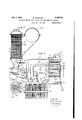
- FIG. 1 is a diagrammatic view of a plant, partly in section, in which the cooling water is conducted into the surface heat-exchangers of the compressor in series and is mixed with the com- 10 pressed air in a separate mixing heat-exchanger,
- Fig. 2 is a diagrammatic view of another embodiment of the arrangement of the surface heat-exchangers and the mixing heat-exchanger, in which the cooling water passes in several 15 cycles in parallel through said surface heat-exchanger,
- Fig. 3 is a sectional view of a surface heat-exchanger used in the plant shown in Figs. 1 and 2,
- Fig. 4 is a diagrammatic view of another em- 20 bodiment of the plant, in which the cooling water is mixed with the compressed air in a chamber of the surface heat-exchangers and the mixture of water and air passes through the tubes of the surface heat-exchangers in series, 25
- Fig. 5 is a longitudinal sectional view of the surface heat-exchanger used in the plant shown in Fig. 4, y
- Fig. 6 is'ar- ⁇ cross-sectional view of the surface heat-exchanger shown in Fig. 5. taken on line so 6--6 of said Fig. 5.
- I D indicates a gas turbine, which drives an electric generator II and a compressor I2 positively connected to the main shaft of the turbine.
- the compressor has four 35 stages. Every stage is provided with two run ⁇ ners arranged in series, so that every runner performs a portion of the work of compression of of the respective stage.
- the air or other gaseous lmedium to be compressed enters the compressor 4Q I2 through an inlet I3. Afterthe first stage of compression, the air flows through the pipe I4' into the surface heat-exchanger I5 (see Fig. 3) and ⁇ is cooled therein by indirect heat-exchange by ⁇ the water or other liquid medium flowing 45 through the tubes I6' of said heat-exchanger I5.
- the cooled air enters the second stage of the turbo-compressor I2 through the pipe I'I.
- the air is conducted into the surface heat-exchanger I5" 50 through the pipe I4", is cooled by the cooling water running through the tubes I6" thereof and is led into the third stage of the compressor I2 through the pipe Il".
- the air enters the surface 55 heat-exchanger IU'" through the pipe Il'", is cooled in the heat-exchanger by the cooling water running through the tubes II'" thereof and enters the last stage of the compressor through the pipe I 1"'.
- the mixing heat-exchanger is divided into two chambers n and 2
- the pump 2l sucks the cooling water from the chamber 20 of the mixing heat-exchanger I8 and discharges the cooling water into the tubes I6"" of the surface heat-exchanger
- the cooling water carrying the heat of compression of the last stage flows through the pipes 26"", 25" into the tubes Ii'" of the heat-exchanger IS'", where it receives the heat of compression of the third stage.
- the cooling water flows .in series through the pipes 26"', 2B", the tubes IB" of the heat-exchanger I5", the pipes 28", 25' and the tubes I6 of the heatexchanger I5.
- the heated cooling water carrying the heat of compression of all stages leaves the surface heat-exchanger I5' through the pipe 2l' connected to the line 26, which leads the heated cooling water into the upper chamber 2
- the heated cooling water is discharged from the line 26' through a plurality of spraying nozzles 21 and flows through the trickling bed 28 in a direction opposite to the flow of compressed air coming from the pipe I9.
- the temperature in the mixing heat-exchanger is below the temperature pertaining to the boiling temperature of the water at the pressure existing in said mixing heat-exchanger due to the pressure of the compressed air.
- the entire heat of compression is returned into the thermodynamic cycle of the plant and is not lost in the cooling water.
- the volume of the gaseous medium to be introduced into the combustion chamber of the gas turbine is increased by the volume of the vapors in the air-vapor mixture, which are obtained by the vaporization of the cooling water under the above mentioned particular conditions.
- the air-vapor mixture flows through the line 2S into the heat regenerator 30 heated by the waste gases of the gas turbine and then through the line 3
- the fuel enters the combustion chamber 32 through the pipe I3.
- the mixing heat-exchanger is provided with a float 3l connected to a valve 3i, which serves to maintain a predetermined amount. of cooling4 water in the water cycle. If the level of the water in the chamber 20 falls, the i'ioat 3l opens the valve 25, and fresh supplemental water heated in the preheater
- FIG. 2 shows another embodiment of my invention according to which the cooling water flows in parallel cycles through the surface heat-exchangers i5', I5 and I 5"'. Furthermore. the entire amount of compressed air is led from the last stage of compression into the mixing heat-exchanger II' througl. the pipe Il; there is no fourth surface heat-exchanger
- the mixing heat-exchanger into four chambers 2
- the first cycle is formed by the pump 2l', the tubes of the surface heat-exchanger I5 having the construction shown in Fig. 3, the line 2
- a float 3l connected to a valve serves to admit supplemental water through the line into the receptacle 31', if the level of the cooling water inzthe chamber 20' falls below a predetermined height.
- the operation of the mixing heat-exchanger I8' is the same as the above described mixing heat-exchanger Il arranged in the embodiment shown in Fig. l.
- the compressed air and the cooling water flow in a direction opposite 'to each other. a portion of the water is vaporized at a temperature below the temperature of the boiling point of the water at the pressure in the mixing'heat-exchanger determined by the pressure of the compressed air.
- the cooled water is returned into the different cycles of cooling water, and the compressed air mismos charged with moisture leaves the mixing heati miilethsfuelusedinthel'bovedescribedemexchanger il' through the line 20 to be introducedinto the combustion chamber of the gas turbine.
- Fig. 4 shows still another embodiment of the plant according to my invention.
- the cooling medium ilows in series through the surface heat-exhangers
- a fourth surface heat-exchanger has beenl omitted and the. entire amount of compressed air is led into the combustion chamber 32 of the gas-turbine I0.
- Figs. ⁇ 5 and 6 illustrate in an enlarged scale a surface heat-exchanger as it maybe used in the embodiment of the plant shown in Fig. 4.
- the air enters the surface heat-exchanger I 00 through the line
- the compressed air flows through the surface heat-exchangers
- the air-vapor mixture leaves the surface heat-exchanger
- the air-vapor mixture ready for the introduction into the combustion chamber of the combustion engine leaves the surface heatexchanger IGO' through the line. 200, and enters the combustion chamber 32 of the turbine I0 through the heat-regenerator 30 and the line 3
- 80", I80" is provided with a float 34', 34", 34', connected to a valve 35', 35", 35"' for theadmission of supplemented ⁇ water through the line 36', 36", 36"', if the level of the water in the mixing chamber falls below a predetermined height.
- bodiments is a liquid fuel
- a gaseous fuel such as regenerator-gas or blast-furnace-gas could be used for the operation of the combustion engine.
- the gaseous fuel enteringthe combustion chamber of the combustion engine must be at the same pressure as the compressed air entering said combustion chamber.
- the gaseous fuel must be compressed prior to its introductlon'intn the combustion chamber.
- heat of compression is produced by the compression of the gaseous fuel or medium, and the same methods as described above .in connection with the heat of compression produced by the compression of 'the air may be applied to the utilization of the heat of compression produced by the compressione! the gaseous fuel, so that vapors may be formed in heat-exchangers by said heat of compression produced by the compression of the gaseous fuel or medium which may be introduced into the compressed gaseous fuel or medium to be led into the combustion chamber of the engine.
- a plant comprising a combustion engine and a compressor driven by said combustion engine for the production of a compressed gaseous medium to be introduced into the combustion chamber of said combustion engine, the stops of compressing the gaseous medium in several stages to a predetermined pressure, branching ott a portion oi the compressed gaseous medium from the last stage to a place of consumption, transferring the heat of compression after every stage 'with the exception of the last stage into a liquid cooling medium by indirect heat-exchanger, leading the liquid cooling medium in a single cycle in series through the several places oi' indirect heat-exchange, mixing the liquid cooling medium carrying the heat of compression with the unbranched portion of the compressed gaseous medium discharged from the last stage of the compressor, evaporating a part of said heated liquid cooling medium in presence of said compressed gaseous medium at a temperature below the temperature pertaining to the boiling point oi said liquid medium at the pressure determined by the pressure of the compressed gaseous medium and cooling thereby the remaining part of
- the heated liquid cooling medium to cooling temperature, conducting the mixture oi gaseous medium and vapors thus obtained into the combustion chamber of the comto their introduction into the combustion cham- ⁇ ber of the combustion engine, and using again the cooled liquid cooling medium for the reception of the heat oi' compression.
- a plant comprising: a combustion engine, a multi-stage compressor driven by said combustion engine for the production of a compressed gaseous medium, a plurality of surface heat-exchangers connected to said compressor for the indirect heat-transfer between the compressed gaseous medium and a liquid cooling medium after each stage of compression with the exception of the last stage of compression, a mixing heat-exchanger, a pipe connecting the last stage of the compressor with said mixing heat-exchanger for the introduction of the compressed gaseous medium into said mixing heat-exchanger, a system of lines leading ⁇ the liquid cooling medium through said surface heat-exchangers and into said mixing heat-exchanger designed to evaporate a part of the heated liquid cooling medium in the presence of said compressed gaseous medium at a temperature below the temperature pertaining to the boiling point of said liquid medium at the pressure determined by the pressure of the compressed gaseous medium, and a conduit connecting said mixing heat-exchanger with the combustion engine for the introduction of the mixture of gaseous medium and vapors obtained in said mixing heat-exchanger
- a plant comprising: a combustion engine, a multi-stage compressor driven by said combustion engine for the production of a compressed gaseous medium, a plurality of surface heat-exchangers connected to said compressor for the indirect heat-transfer between the compressed gaseous medium and a.
- a mixing heat-exchanger a pipe connecting the last stage of the compressor with said mixing heat-exchanger for the introduction of the compressed gaseous medium into said mixing heat-exchanger, an additional surface heat-exchanger, a line leading to a place of consumption connected to said additional surface heat-exchanger, a branching pipe connecting the last stage of the compressor with said additional surface heat-exchanger for branching off a portion of the compressed gaseous medium into said line of consumption, a system of lines leading the liquid cooling medium through said plurality of surface heat-exchangers and through said additional heat-exchanger and into said mixing heat-exchanger designed to evaporate a part of the heated liquid cooling medium in the presence of said compressed gaseous medium at a temperature below the temperature pertaining to the boiling point of said liquid medium at the pressure determined by the pressure of the compressed gaseous medium, and a conduit connecting said mixing heat-exchanger with the combustion engine for the introduction of the mixture of gaseous
Landscapes
- Engineering & Computer Science (AREA)
- Chemical & Material Sciences (AREA)
- Combustion & Propulsion (AREA)
- Mechanical Engineering (AREA)
- General Engineering & Computer Science (AREA)
- Engine Equipment That Uses Special Cycles (AREA)
Description
M. MARTINKA 2,186,706
COMBUSTION ENGINE AND A METHOD FOR THE OPERATION THEREOF Jan. 9, 1940.
Filed Nov. 14, 1934 5 Sheets-Sheet 2 Jan. 9, 1940. M MART|NKA 2,186,706
. COMBUSTION ENGINE AND A METHOD FOR THE `OPERATION THEREOF Patented Jan. 9, v1940 COMBUSTIO ENGINE AND A METHOD FOR THE OPERATION THEBEOF Michael Martinka, Duisburg, Germany Application November 14, 1934, Serial No. 753,068
Germany November 14, 1933 11 Claims. (Cl. Bti-542) My invention relates to a plant comprising a combustion engine and a compressor for the production of compressed air required for the combustion of fuel and to a method for the operation of said plant. More particularly, my invention is concerned with a plant comprising a combustion gas turbine and a multi-stage air compressor driven by same.
It is understood that the term combustion engine" used in the specification and claims has reference to an internal combustion engine with pistons and to a combustion gas turbine.
One object of my invention is to provide a plant and a method for the operation of same, by means of which the heat, which is generated during the compression of the air to be introduced into the combustion chamber and is transferred into the cooling water in the intercoolers, may be utilized for the combustion engine.
In order to carry out my inventioninfo practice, my method comprises the stepsof compressing the air to a predetermined pressure, transferring the heat of compression into the cooling water by indirect heat-exchange, mixing the cooling water carrying the heat of the compression with the compressed air discharged from the compressor, evaporating a part of said heated cooling water in presence of lsaid compressed air at a temperature being -below the temperature pertaining to the boiling point of said water at the pressure given by the pressure of compressed air and cooling thereby the remaining part of the heated cooling medium to cooling temperature conducting the mixture of air and vaporsathus obtained into the combustion chamber of "fthe combustion engine, and using again the. cooled water for the reception of the heat of compression. There are various embodiments of fthe plant possible for said method, slimev preferred embodiments will be described later on. be readily understood, my invention permits the return of the heat of compression into the thermodynamic cycle of the plant and the obtainance voi the increased amount of the medium to be added to the fuel for lowering the combustion temperatures by the vapors mixed with the air, which are produced by the above mentioned particular vaporization of the heated cooling water. As the heated cooling water is cooled to cooling temperature during the above mentioned vaporization of a part of the cooling water,- the entire heat ofcompression is in the vapors of the alrvapor mixture and is returned into the thermodynamic cycle. The requirements for excess air is AS Will considerably reduced. and the compressor does not need to be oversized to a great extent.
The above objects aswell as others n'ot particularly pointed out will appear from the following description with reference to the accom- 5 panying drawings, in which Fig. 1 is a diagrammatic view of a plant, partly in section, in which the cooling water is conducted into the surface heat-exchangers of the compressor in series and is mixed with the com- 10 pressed air in a separate mixing heat-exchanger,
Fig. 2 is a diagrammatic view of another embodiment of the arrangement of the surface heat-exchangers and the mixing heat-exchanger, in which the cooling water passes in several 15 cycles in parallel through said surface heat-exchanger,
Fig. 3 is a sectional view of a surface heat-exchanger used in the plant shown in Figs. 1 and 2,
Fig. 4 is a diagrammatic view of another em- 20 bodiment of the plant, in which the cooling water is mixed with the compressed air in a chamber of the surface heat-exchangers and the mixture of water and air passes through the tubes of the surface heat-exchangers in series, 25
Fig. 5 is a longitudinal sectional view of the surface heat-exchanger used in the plant shown in Fig. 4, y
Fig. 6 is'ar-` cross-sectional view of the surface heat-exchanger shown in Fig. 5. taken on line so 6--6 of said Fig. 5.
Referring now to Fig. 1, I D indicates a gas turbine, which drives an electric generator II and a compressor I2 positively connected to the main shaft of the turbine. The compressor has four 35 stages. Every stage is provided with two run` ners arranged in series, so that every runner performs a portion of the work of compression of of the respective stage. The air or other gaseous lmedium to be compressed enters the compressor 4Q I2 through an inlet I3. Afterthe first stage of compression, the air flows through the pipe I4' into the surface heat-exchanger I5 (see Fig. 3) and` is cooled therein by indirect heat-exchange by `the water or other liquid medium flowing 45 through the tubes I6' of said heat-exchanger I5. Then, the cooled air enters the second stage of the turbo-compressor I2 through the pipe I'I. After the second stage of compression the air is conducted into the surface heat-exchanger I5" 50 through the pipe I4", is cooled by the cooling water running through the tubes I6" thereof and is led into the third stage of the compressor I2 through the pipe Il". Likewise. after the third Stage of compression. the air enters the surface 55 heat-exchanger IU'" through the pipe Il'", is cooled in the heat-exchanger by the cooling water running through the tubes II'" thereof and enters the last stage of the compressor through the pipe I 1"'. After the last stage of compression, the air being under a predetermined pressure enters the mixing heat-exchanger i8 through the pipe I9, so that substantially the same pressure prevails behind the mixing heat-exchanger il as in the last stage of the compressor 2. The mixing heat-exchanger is divided into two chambers n and 2| by a perforated partition 22. 'I'he lower chamber is partly filled with water, and the upper chamber 2| is partly filled with inert illling material such as Raschig rings 2l.
There is another surface heat-exchanger I8"", into which a portion of the compressed air flows from the last stage of the compressor I2 through the pipe |4". This portion of the compressed air, which may be used at any place of consumption, for example as motive power in pneumatic motors or the like, is cooled by the water running through the tubes I6"" of the heat-exchanger I5"" and flows in dry condition through the line 2l to the place of consumption. While the compressed air entering the mixing heatexchanger Il is introduced into the combustion chamber of the gas turbine as will be described later on, the portion of the compressed air entering the surface heat-exchanger W'" is conducted to a place remote from the gas turbine. 'I'he cycle of the cooling water is as follows: The pump 2l sucks the cooling water from the chamber 20 of the mixing heat-exchanger I8 and discharges the cooling water into the tubes I6"" of the surface heat-exchanger |5"" through the pipe The cooling water carrying the heat of compression of the last stage flows through the pipes 26"", 25" into the tubes Ii'" of the heat-exchanger IS'", where it receives the heat of compression of the third stage. Then the cooling water flows .in series through the pipes 26"', 2B", the tubes IB" of the heat-exchanger I5", the pipes 28", 25' and the tubes I6 of the heatexchanger I5. The heated cooling water carrying the heat of compression of all stages leaves the surface heat-exchanger I5' through the pipe 2l' connected to the line 26, which leads the heated cooling water into the upper chamber 2| of the mixing heat-exchanger i8. The heated cooling water is discharged from the line 26' through a plurality of spraying nozzles 21 and flows through the trickling bed 28 in a direction opposite to the flow of compressed air coming from the pipe I9. The temperature in the mixing heat-exchanger is below the temperature pertaining to the boiling temperature of the water at the pressure existing in said mixing heat-exchanger due to the pressure of the compressed air. As the compressed air coming from the compressor is non-saturated with moisture, a' part of the heated cooling water coming from the spraying nozzles 21 is vaporized in the mixing chamber 2| by direct heat-exchange at the given temperature and pressure, whereby the heat for the vaporization of the water is taken from the water, which is cooled to the original cooling temperature of the cooling water, and from the compressed air, which at the same time is saturated and charged with moisture. Thus, an air-vapor mixture is formed in the mixing heat-exchanger I8 and the heat of compression carried by the heated cooling water in the line 25 is transferred into the vapors of the air-vapor mixture. As the alr-vapor mixture is conducted into the combustion chamber of the gas turbine, as will be described hereinafter, the entire heat of compression is returned into the thermodynamic cycle of the plant and is not lost in the cooling water. On the other hand, the volume of the gaseous medium to be introduced into the combustion chamber of the gas turbine is increased by the volume of the vapors in the air-vapor mixture, which are obtained by the vaporization of the cooling water under the above mentioned particular conditions. The air-vapor mixture flows through the line 2S into the heat regenerator 30 heated by the waste gases of the gas turbine and then through the line 3| into the combustion chamber 32 of the gas turbine I 0. The fuel enters the combustion chamber 32 through the pipe I3.
The mixing heat-exchanger is provided with a float 3l connected to a valve 3i, which serves to maintain a predetermined amount. of cooling4 water in the water cycle. If the level of the water in the chamber 20 falls, the i'ioat 3l opens the valve 25, and fresh supplemental water heated in the preheater |36 may enter the mixing chamber 2| through the line 3l.
While in the embodiment shown in Fig. l the cooling water ows in series through the surface heat-exchangers |5"", IU, Il" and I5', Fig. 2 shows another embodiment of my invention according to which the cooling water flows in parallel cycles through the surface heat-exchangers i5', I5 and I 5"'. Furthermore. the entire amount of compressed air is led from the last stage of compression into the mixing heat-exchanger II' througl. the pipe Il; there is no fourth surface heat-exchanger |5"" through which a portion of the compressed air is led to a place of consumption. 'I'he mixing heat-exchanger il has three perforated partitions 22', 22" and 22"'. which divide the mixing heat-exchanger into four chambers 2|', 2|", 2I" and 20' and may receive beds 2l', 28" and 28"' of "Raschig rings." There are three parallel cycles of cooling water. The first cycle is formed by the pump 2l', the tubes of the surface heat-exchanger I5 having the construction shown in Fig. 3, the line 2|', the spraying nozzles 21', a receptacle Il for the reception of the non-vaporized and cooled water leaving the trickling bed 28', and the line Il'. 'I'he second cycle is formed by the pump 24", the tubes of the surface heat-exchanger I5", the line 26", the spraying nozzles 21", the receptacle 3l", and the line 38". The third cycle is formed by the pump 24"', the tubes of the surface heat-exchanger IS'", the line 26"', the spraying nozzles 21"', the chamber 2U' receiving the non-vaporized cooled water from the trickling bed 28"', and the line Il!" The spraying nozzles 21', 21", 21"', the trickling beds 28', 28", 28"' and the receptacles 31', 31", 20' are arranged in different levels above each other. A float 3l connected to a valve serves to admit supplemental water through the line into the receptacle 31', if the level of the cooling water inzthe chamber 20' falls below a predetermined height. The operation of the mixing heat-exchanger I8' is the same as the above described mixing heat-exchanger Il arranged in the embodiment shown in Fig. l. The compressed air and the cooling water flow in a direction opposite 'to each other. a portion of the water is vaporized at a temperature below the temperature of the boiling point of the water at the pressure in the mixing'heat-exchanger determined by the pressure of the compressed air. the cooled water is returned into the different cycles of cooling water, and the compressed air mismos charged with moisture leaves the mixing heati miilethsfuelusedinthel'bovedescribedemexchanger il' through the line 20 to be introducedinto the combustion chamber of the gas turbine.
Fig. 4 shows still another embodiment of the plant according to my invention. In this irl-- stance, the cooling medium ilows in series through the surface heat-exhangers |50'", |50" and likewise to the embodiment shown in Fig. 1, but a separate mixing heat-exchanger has lbeen omitted and the intimate mixing of the compressed air with water takes place in the surlface heat-exchangers, and the cooling medium receiving the heat of compression in the tubes of the surface heat-exchangers is an air-moisture mixture. Furthermore, likewise as to the embodiment shown in Fig. 2, a fourth surface heat-exchanger has beenl omitted and the. entire amount of compressed air is led into the combustion chamber 32 of the gas-turbine I0. Figs.` 5 and 6 illustrate in an enlarged scale a surface heat-exchanger as it maybe used in the embodiment of the plant shown in Fig. 4. After the first stage of compression the air enters the surface heat-exchanger I 00 through the line |40', is cooled by the cooling medium flowing through the ltubes |60" which may be provided with a plurality of horizontal ribs |0|' at their outside, and leaves the surface heat-exchanger through the'line |10'. Likewise, the compressed air flows through the surface heat-exchangers ||i0' v and |00'", after the second and third. stageof compression. After the last stage of compression, the entire amount of compressed air flows through the line l0 into a mixing chamber |80" arranged below the series of vertical tubes |00' of the surface heat-exchanger |50"'. The lower part of this mixing chamber |00"' is filled with water, and a pump 240'" sucks the water from the lower part of said chamber |80 and forces the water through the line 260'" and spraying nozzle 210' into the upper part of mixing chamber |80". The conditions of pressure and temperature in the mixing chamber I30." and within .the tubes |80" connected thereto are the same as described in connection with the mixing heat-exchanger in the embodiments shown in Figs. 1 and 2, so that a part of the water is vaporized and the air is charged with moisture within said chamber |80" and the tubes |60", while the non-vaporized and cooled water drops into the lower part of the chamber |80"'. The air-vapor mixture leaves the surface heat-exchanger |50"' through the line 290" and enters the mixing chamber |00" of the surface heat-exchanger |50", -where the pump 240" discharges water through the nozzle 210", so that the same phenomena takes place as in the surface heatexchanger |50"'. Likewise, the air-vapor mixture leaves the surface heat-exchanger |50" through the line 290', enters the mixing chamber |80' of the surface heat-exchanger |30', and is mixed with water delivered from the pump 240. Finally, the air-vapor mixture ready for the introduction into the combustion chamber of the combustion engine leaves the surface heatexchanger IGO' through the line. 200, and enters the combustion chamber 32 of the turbine I0 through the heat-regenerator 30 and the line 3|. Each of the mixing chambers |80', |80", I80" is provided with a float 34', 34", 34', connected to a valve 35', 35", 35"' for theadmission of supplemented `water through the line 36', 36", 36"', if the level of the water in the mixing chamber falls below a predetermined height.
bodiments is a liquid fuel, a gaseous fuel, such as regenerator-gas or blast-furnace-gas could be used for the operation of the combustion engine. In such an instance, the gaseous fuel enteringthe combustion chamber of the combustion engine must be at the same pressure as the compressed air entering said combustion chamber. In other words, the gaseous fuel must be compressed prior to its introductlon'intn the combustion chamber. Under these circumstances, heat of compression is produced by the compression of the gaseous fuel or medium, and the same methods as described above .in connection with the heat of compression produced by the compression of 'the air may be applied to the utilization of the heat of compression produced by the compressione! the gaseous fuel, so that vapors may be formed in heat-exchangers by said heat of compression produced by the compression of the gaseous fuel or medium which may be introduced into the compressed gaseous fuel or medium to be led into the combustion chamber of the engine.
I have described preferred embodiments of my inventiombut it is clear that -numerous changes and omissions may be made without departing from the spirit. of my invention. For example, an internal combustion engine having pistons could be used inany of the illustrated embodiments instead of a combustion gas-turbine.
I claim: I
1. In a method i'or the operation of a plant comprising a combustion engine/and a compressor driven by said comb tion engine for the production of a compressed aseous medium to be introduced into the combustion chamber of said combustion engine, the steps of compressing the gaseous medium to a predetermined pressure, transferring the heat of compression into a liquid cooling medium byindirect heat-exchange,I mixing the'llquid cooling medium carrying the heat of the compression lwith the compressed gaseous medium discharged from the compressor, evaporating a part of said heated liquid cooling medium in presence of said compressed gaseous medium at a temperature below the temperature pertaining to the boiling point of said liquid medium at the pressure determined by thepressure of the compressed gaseous medium and cooling thereby the remaining part of the heated liquid cooling medium to cooling temperature, conducting the` mixture of gaseous medium and vapors thus obtained into the combustion chamber of the combustion engine, and using again the cooled liquid cooling medium for the reception of the heat of compression. f
2. In a method for the operation of a plant comprising a combustion engineand a compressor driven by said combustion engine for the production of a compressed gaseous medium to be introduced into the combustion chamber of said combustion engine, the steps of compressing the gaseous medium to a predetermined pressure, branching ofi' a portion of the compressed gaseous medium to a place of consumption, transferring the heat of compression into a liquid cooling medium by indirect heat-exhange, mixing the liquid cooling medium carrying the heat of compression with the un-branched portion of the compressed gaseous medium discharged from the compressor, evaporating a part of said heated liquid cooling medium in presence of said compressed gaseous medium at a temperature below the temperature pertaining to the boiling point of said liquid medium at the pressure determined by the pressure ot the compressed gaseous medium and cooling thereby the remaining part of the heated liquid cooling medium to cooling temperature, conducting the mixture oi gaseous 5 medium and vapors thus obtained into the combustion chamber of the combustion engine, and
using again the cooled liquid cooling medium for the reception of the heat of compression.
3. In a method for the operation of a plant comprising a combustion engine and a com pressor driven by said combustion engine for the production of a compressed gaseous medium to be introduced intothe combustion` chamber of said combustion engine, the steps of compressing the gaseous medium in several stages to a predetermined pressure, transferring the heat of compression after every stage with the exception of the last stage into a liquid cooling medium by indirect heat-exchange, leading the liquid cooling medium in a single cycle in series through the several places of indirect heat-exchange, mixing the liquid cooling medium carrying the heat ot compression with the compressed gaseousV medium discharged from the last stage of the compressor. evaporating a part of said heated liquid cooling medium in presence of said compressed gaseous medium at a temperature below the temperature pertaining to the boiling point of said liquid medium at the pressure determined by the pressure of the compressed gaseous medium and cooling thereby the remaining part of the heated liquid cooling medium to cooling temperature. conducting the mixture of gaseous medium and vapors thus obtained into the combustion chamber of the combustion engine, and using again the cooled liquid cooling medium for the reception of the heat oi' compression.
4. In a method for the operation of a plant comprising a combustion engine and a compressor driven by said combustion engine for the production oi' a compressed gaseous medium to be introduced into the combustion chamber of said combustion engine, the steps of compressing the gaseous medium in several stages to a predetermined pressure, transferring the heat of compression after every stage with the exception of the last stage into a liquid cooling medium by indirect heat exchange, leading the liquid cooling medium in several cycles in parallel through the several places of indirect heat-exchange, mixing the liquid cooling medium carrying the heat of compression with the compressed gaseous medium discharged from the last stage of the compressor, evaporating a part of said heated liquid cooling medium in presence of said compressed gaseous medium at a temperature below the temperature pertaining to the boiling point of said liquid medium at the pressure determined by the pressure of the compressed gaseous medium and cooling thereby the remaining part of the heated liquid cooling medium to cooling temperature, conducting the Vmixture of gaseous medium and vapors thus obtained into the combustlon chamber of the combustion engine, and using again the cooled liquid cooling medium for the reception of the heat of compression.
5. In a method for the operation of a plant comprising a combustion engine and a compressor driven by said combustion engine for the production of a compressed gaseous medium to be introduced into the combustion chamber of said combustion engine, the steps of compressing the gaseous medium in several stages to a predetermined pressure, transferring the heat o! compression after every stage with the exception of the last stage4 into a liquid cooling mediumi by indirect heat exchange. leading the liquid cooling medium in several cycles in parallel through the several places of indirect heat exchange, leading the liquid cooling medium ci all said cycles in different levels into a heat-exchanger and mixing therein the liquid cooling medium carrying the heat of compression with the compressed gaseous medium discharged from the last stage of the compressor, evaporating a part of said heated liquid cooling medium in presence oi' said compressed gaseous medium at a temperature below the temperature pertaining to the boiling point of said liquid medium at the pressure determined by the pressure ot the compressed gaseous medium and cooling thereby the remaining part of the heated liquid cooling medium to cooling temperature, conducting the mixture of gaseous medium and vapors thus obtained into the combustion chamber of the combustion engine, and using again the cooled liquid cooling medium for the reception of the heat of compression.
6. In a method for the operation oi a plant comprising a combustion engine and a compressor driven by said combustion engine for the production of a compressed gaseous medium to be introduced into the combustion chamber of said combustion engine, the stops of compressing the gaseous medium in several stages to a predetermined pressure, branching ott a portion oi the compressed gaseous medium from the last stage to a place of consumption, transferring the heat of compression after every stage 'with the exception of the last stage into a liquid cooling medium by indirect heat-exchanger, leading the liquid cooling medium in a single cycle in series through the several places oi' indirect heat-exchange, mixing the liquid cooling medium carrying the heat of compression with the unbranched portion of the compressed gaseous medium discharged from the last stage of the compressor, evaporating a part of said heated liquid cooling medium in presence of said compressed gaseous medium at a temperature below the temperature pertaining to the boiling point oi said liquid medium at the pressure determined by the pressure of the compressed gaseous medium and cooling thereby the remaining part of the heated liquid cooling medium to cooling temperature, conducting the mixture of gaseous medium and vapors thus obtained into the combustion chamber of the combustion engine, and using again the cooled liquid cooling medium for the reception of the heat oi compression.
7. In a method for the operation of a plant comprising a combustion engine and a compressor driven by said combustion engine for the production oi a compressed gaseous medium to be introduced into the combustion chamber of said combustion engine, the steps of compressing the gaseous medium in several stages to a predetermined pressure, mixing a liquid cooling medium with the compressed gaseous medium discharged from the last stage of the compressor, evaporating a part of said liquid cooling medium in presence o! said compressed gaseous medium at a temperature below the temperature pertaining to the boiling point of said liquid medium at the pressure determined by the pressure of the compressed gaseous medium and cooling thereby the remaining part o! the heated liquid cooling medium to cooling temperature, conducting the mixture oi gaseous medium and vapors thus obtained into the combustion chamber of the comto their introduction into the combustion cham-` ber of the combustion engine, and using again the cooled liquid cooling medium for the reception of the heat oi' compression.
8. A plant comprising: a combustion engine, a multi-stage compressor driven by said combustion engine for the production of a compressed gaseous medium, a plurality of surface heat-exchangers connected to said compressor for the indirect heat-transfer between the compressed gaseous medium and a liquid cooling medium after each stage of compression with the exception of the last stage of compression, a mixing heat-exchanger, a pipe connecting the last stage of the compressor with said mixing heat-exchanger for the introduction of the compressed gaseous medium into said mixing heat-exchanger, a system of lines leading `the liquid cooling medium through said surface heat-exchangers and into said mixing heat-exchanger designed to evaporate a part of the heated liquid cooling medium in the presence of said compressed gaseous medium at a temperature below the temperature pertaining to the boiling point of said liquid medium at the pressure determined by the pressure of the compressed gaseous medium, and a conduit connecting said mixing heat-exchanger with the combustion engine for the introduction of the mixture of gaseous medium and vapors obtained in said mixing heat-exchanger into said combustion engine.
9. A plant comprising: a combustion engine, a multi-stage compressor driven by said combustion engine for the production of a compressed gaseous medium, a plurality of surface heat-exchangers connected to said compressor for the indirect heat-transfer between the compressed gaseous medium and a. liquid cooling medium after each stage of compression with the exception of the last stage of compression, a mixing heat-exchanger, a pipe connecting the last stage of the compressor with said mixing heat-exchanger for the introduction of the compressed gaseous medium into said mixing heat-exchanger, an additional surface heat-exchanger, a line leading to a place of consumption connected to said additional surface heat-exchanger, a branching pipe connecting the last stage of the compressor with said additional surface heat-exchanger for branching off a portion of the compressed gaseous medium into said line of consumption, a system of lines leading the liquid cooling medium through said plurality of surface heat-exchangers and through said additional heat-exchanger and into said mixing heat-exchanger designed to evaporate a part of the heated liquid cooling medium in the presence of said compressed gaseous medium at a temperature below the temperature pertaining to the boiling point of said liquid medium at the pressure determined by the pressure of the compressed gaseous medium, and a conduit connecting said mixing heat-exchanger with the combustion engine for the introduction of the mixture of gaseous medium and vapors obtained in said mixing heat-exchanger into said combustion engine.
l0. A plant as claimed in claim 8, in which said system of lines leads the liquid cooling medium in a single cycle in series through said surface heat-exchangers.
1l. A plant as claimed in claim 9, in which said system of lines leads the liquid cooling medium in a single cycle in series through said additional surface heat-exchanger and said plurality of surface heat-exchangers.
ncIcHAEL Mmmm.
Applications Claiming Priority (1)
| Application Number | Priority Date | Filing Date | Title |
|---|---|---|---|
| DE2186706X | 1933-11-14 |
Publications (1)
| Publication Number | Publication Date |
|---|---|
| US2186706A true US2186706A (en) | 1940-01-09 |
Family
ID=7989135
Family Applications (1)
| Application Number | Title | Priority Date | Filing Date |
|---|---|---|---|
| US753068A Expired - Lifetime US2186706A (en) | 1933-11-14 | 1934-11-14 | Combustion engine and a method for the operation thereof |
Country Status (1)
| Country | Link |
|---|---|
| US (1) | US2186706A (en) |
Cited By (36)
| Publication number | Priority date | Publication date | Assignee | Title |
|---|---|---|---|---|
| US2548508A (en) * | 1946-03-05 | 1951-04-10 | Alfred S Wolfner | Thermal system |
| US2584232A (en) * | 1946-09-04 | 1952-02-05 | Rateau Soc | Gas turbine power plant, including means to treat combustion products between successive stages of expansion |
| US2672953A (en) * | 1946-08-02 | 1954-03-23 | Clayton Manufacturing Co | Dynamometer with built-in heat exchanger |
| US2678532A (en) * | 1951-03-16 | 1954-05-18 | Chemical Foundation Inc | Gas turbine process using two heat sources |
| US2718753A (en) * | 1951-01-02 | 1955-09-27 | Phillips Petroleum Co | Improved operation of internal combustion engine operating on liquid petroleum gas fuel |
| US2763985A (en) * | 1951-02-08 | 1956-09-25 | Garrett Corp | Fuel control for turbine driven compressor unit |
| US2777288A (en) * | 1952-04-02 | 1957-01-15 | Glinka Carl | Process and apparatus for the generation of mechanical energy from solid fuels having a high water content |
| US2781635A (en) * | 1952-04-26 | 1957-02-19 | Freeport Sulphur Co | Process and heating system for providing hot water and power for sulfur mining |
| US2801821A (en) * | 1953-02-05 | 1957-08-06 | Bbc Brown Boveri & Cie | Cooled turbine casing |
| US2869324A (en) * | 1956-11-26 | 1959-01-20 | Gen Electric | Gas turbine power-plant cycle with water evaporation |
| US2939282A (en) * | 1954-04-07 | 1960-06-07 | Studebaker Packard Corp | Intake and exhaust ducting for gas turbine engine |
| US3731485A (en) * | 1970-02-07 | 1973-05-08 | Metallgesellschaft Ag | Open-cycle gas turbine plant |
| US4057371A (en) * | 1974-05-03 | 1977-11-08 | Norwalk-Turbo Inc. | Gas turbine driven high speed centrifugal compressor unit |
| US4448018A (en) * | 1980-11-25 | 1984-05-15 | Mitsubishi Gas Chemical Company, Inc. | Method for adding water to a heat exchanging system |
| US4537023A (en) * | 1981-12-10 | 1985-08-27 | Mitsubishi Gas Chemical Company, Inc. | Regenerative gas turbine cycle |
| FR2563575A1 (en) * | 1984-04-27 | 1985-10-31 | Gen Electric | FLUID INJECTION GAS TURBINE ENGINE AND METHOD OF OPERATION |
| US4653268A (en) * | 1981-12-10 | 1987-03-31 | Mitsubishi Gas Chemical Co., Inc. | Regenerative gas turbine cycle |
| US4657009A (en) * | 1984-05-14 | 1987-04-14 | Zen Sheng T | Closed passage type equi-pressure combustion rotary engine |
| US4753068A (en) * | 1987-01-15 | 1988-06-28 | El Masri Maher A | Gas turbine cycle incorporating simultaneous, parallel, dual-mode heat recovery |
| US4829763A (en) * | 1984-02-01 | 1989-05-16 | Fluor Corporation | Process for producing power |
| US5181376A (en) * | 1990-08-10 | 1993-01-26 | Fluor Corporation | Process and system for producing power |
| US5218815A (en) * | 1991-06-04 | 1993-06-15 | Donlee Technologies, Inc. | Method and apparatus for gas turbine operation using solid fuel |
| US5379589A (en) * | 1991-06-17 | 1995-01-10 | Electric Power Research Institute, Inc. | Power plant utilizing compressed air energy storage and saturation |
| US5386688A (en) * | 1993-04-23 | 1995-02-07 | Cascaded Advanced Turbine Limited Partnership | Method of generating power with high efficiency multi-shaft reheat turbine with interccooling and recuperation |
| US5398497A (en) * | 1991-12-02 | 1995-03-21 | Suppes; Galen J. | Method using gas-gas heat exchange with an intermediate direct contact heat exchange fluid |
| US6578354B2 (en) | 2000-01-21 | 2003-06-17 | Hitachi, Ltd. | Gas turbine electric power generation equipment and air humidifier |
| US6644013B1 (en) | 1998-10-23 | 2003-11-11 | Hitachi, Ltd. | Gas turbine power generation equipment and air humidifying apparatus |
| US20040031269A1 (en) * | 2002-06-28 | 2004-02-19 | Peter Jansohn | Method for intermediate cooling and gas turbine system with intermediate cooling |
| US7007453B2 (en) | 2002-07-20 | 2006-03-07 | Idalex Technologies, Inc. | Power system and method |
| US20060107646A1 (en) * | 2000-01-21 | 2006-05-25 | Shigeo Hatamiya | Gas turbine electric power generation equipment and air humidifier |
| US20070280400A1 (en) * | 2005-08-26 | 2007-12-06 | Keller Michael F | Hybrid integrated energy production process |
| US20180346142A1 (en) * | 2015-06-25 | 2018-12-06 | Pratt & Whitney Canada Corp. | Engine assembly for an auxiliary power unit |
| US10590842B2 (en) | 2015-06-25 | 2020-03-17 | Pratt & Whitney Canada Corp. | Compound engine assembly with bleed air |
| US10696417B2 (en) | 2015-06-25 | 2020-06-30 | Pratt & Whitney Canada Corp. | Auxiliary power unit with excess air recovery |
| US10710738B2 (en) | 2015-06-25 | 2020-07-14 | Pratt & Whitney Canada Corp. | Auxiliary power unit with intercooler |
| US11492964B2 (en) | 2020-11-25 | 2022-11-08 | Michael F. Keller | Integrated supercritical CO2/multiple thermal cycles |
-
1934
- 1934-11-14 US US753068A patent/US2186706A/en not_active Expired - Lifetime
Cited By (49)
| Publication number | Priority date | Publication date | Assignee | Title |
|---|---|---|---|---|
| US2548508A (en) * | 1946-03-05 | 1951-04-10 | Alfred S Wolfner | Thermal system |
| US2672953A (en) * | 1946-08-02 | 1954-03-23 | Clayton Manufacturing Co | Dynamometer with built-in heat exchanger |
| US2584232A (en) * | 1946-09-04 | 1952-02-05 | Rateau Soc | Gas turbine power plant, including means to treat combustion products between successive stages of expansion |
| US2718753A (en) * | 1951-01-02 | 1955-09-27 | Phillips Petroleum Co | Improved operation of internal combustion engine operating on liquid petroleum gas fuel |
| US2763985A (en) * | 1951-02-08 | 1956-09-25 | Garrett Corp | Fuel control for turbine driven compressor unit |
| US2678532A (en) * | 1951-03-16 | 1954-05-18 | Chemical Foundation Inc | Gas turbine process using two heat sources |
| US2777288A (en) * | 1952-04-02 | 1957-01-15 | Glinka Carl | Process and apparatus for the generation of mechanical energy from solid fuels having a high water content |
| US2781635A (en) * | 1952-04-26 | 1957-02-19 | Freeport Sulphur Co | Process and heating system for providing hot water and power for sulfur mining |
| US2801821A (en) * | 1953-02-05 | 1957-08-06 | Bbc Brown Boveri & Cie | Cooled turbine casing |
| US2939282A (en) * | 1954-04-07 | 1960-06-07 | Studebaker Packard Corp | Intake and exhaust ducting for gas turbine engine |
| US2869324A (en) * | 1956-11-26 | 1959-01-20 | Gen Electric | Gas turbine power-plant cycle with water evaporation |
| US3731485A (en) * | 1970-02-07 | 1973-05-08 | Metallgesellschaft Ag | Open-cycle gas turbine plant |
| US4057371A (en) * | 1974-05-03 | 1977-11-08 | Norwalk-Turbo Inc. | Gas turbine driven high speed centrifugal compressor unit |
| US4448018A (en) * | 1980-11-25 | 1984-05-15 | Mitsubishi Gas Chemical Company, Inc. | Method for adding water to a heat exchanging system |
| US4537023A (en) * | 1981-12-10 | 1985-08-27 | Mitsubishi Gas Chemical Company, Inc. | Regenerative gas turbine cycle |
| US4610137A (en) * | 1981-12-10 | 1986-09-09 | Mitsubishi Gas Chemical Company, Inc. | Regenerative gas turbine cycle |
| US4653268A (en) * | 1981-12-10 | 1987-03-31 | Mitsubishi Gas Chemical Co., Inc. | Regenerative gas turbine cycle |
| US4829763A (en) * | 1984-02-01 | 1989-05-16 | Fluor Corporation | Process for producing power |
| FR2563575A1 (en) * | 1984-04-27 | 1985-10-31 | Gen Electric | FLUID INJECTION GAS TURBINE ENGINE AND METHOD OF OPERATION |
| US4657009A (en) * | 1984-05-14 | 1987-04-14 | Zen Sheng T | Closed passage type equi-pressure combustion rotary engine |
| US4753068A (en) * | 1987-01-15 | 1988-06-28 | El Masri Maher A | Gas turbine cycle incorporating simultaneous, parallel, dual-mode heat recovery |
| EP0275121A3 (en) * | 1987-01-15 | 1989-02-15 | Maher A. El-Masri | Gas turbine cycle incorporating simultaneous, parallel, dual-mode heat recovery |
| US5181376A (en) * | 1990-08-10 | 1993-01-26 | Fluor Corporation | Process and system for producing power |
| US5218815A (en) * | 1991-06-04 | 1993-06-15 | Donlee Technologies, Inc. | Method and apparatus for gas turbine operation using solid fuel |
| US5379589A (en) * | 1991-06-17 | 1995-01-10 | Electric Power Research Institute, Inc. | Power plant utilizing compressed air energy storage and saturation |
| US5398497A (en) * | 1991-12-02 | 1995-03-21 | Suppes; Galen J. | Method using gas-gas heat exchange with an intermediate direct contact heat exchange fluid |
| US5386688A (en) * | 1993-04-23 | 1995-02-07 | Cascaded Advanced Turbine Limited Partnership | Method of generating power with high efficiency multi-shaft reheat turbine with interccooling and recuperation |
| US6901736B2 (en) | 1998-10-23 | 2005-06-07 | Hitachi, Ltd. | Gas turbine electric power generation equipment and air humidifier |
| US6644013B1 (en) | 1998-10-23 | 2003-11-11 | Hitachi, Ltd. | Gas turbine power generation equipment and air humidifying apparatus |
| EP1637713A2 (en) | 1998-10-23 | 2006-03-22 | Hitachi, Ltd. | Gas turbine electric power generation equipment |
| US20040060277A1 (en) * | 1998-10-23 | 2004-04-01 | Hitachi, Ltd. | Gas turbine electric power generation equipment and air humidifier |
| US7096659B1 (en) | 2000-01-21 | 2006-08-29 | Hitachi, Ltd. | Gas turbine electric power generation equipment and air humidifier |
| US20060107646A1 (en) * | 2000-01-21 | 2006-05-25 | Shigeo Hatamiya | Gas turbine electric power generation equipment and air humidifier |
| US7082749B2 (en) | 2000-01-21 | 2006-08-01 | Hitachi, Ltd. | Gas turbine electric power generation equipment and air humidifier |
| US6578354B2 (en) | 2000-01-21 | 2003-06-17 | Hitachi, Ltd. | Gas turbine electric power generation equipment and air humidifier |
| US6966745B2 (en) * | 2002-06-28 | 2005-11-22 | Alstom Technology Ltd. | Method for intermediate cooling and gas turbine system with intermediate cooling |
| US20040031269A1 (en) * | 2002-06-28 | 2004-02-19 | Peter Jansohn | Method for intermediate cooling and gas turbine system with intermediate cooling |
| US7007453B2 (en) | 2002-07-20 | 2006-03-07 | Idalex Technologies, Inc. | Power system and method |
| US8537961B2 (en) | 2005-08-26 | 2013-09-17 | Michael Keller | Hybrid integrated energy production process |
| US7961835B2 (en) | 2005-08-26 | 2011-06-14 | Keller Michael F | Hybrid integrated energy production process |
| US20070280400A1 (en) * | 2005-08-26 | 2007-12-06 | Keller Michael F | Hybrid integrated energy production process |
| US20180346142A1 (en) * | 2015-06-25 | 2018-12-06 | Pratt & Whitney Canada Corp. | Engine assembly for an auxiliary power unit |
| US10501200B2 (en) * | 2015-06-25 | 2019-12-10 | Pratt & Whitney Canada Corp. | Engine assembly for an auxiliary power unit |
| US10590842B2 (en) | 2015-06-25 | 2020-03-17 | Pratt & Whitney Canada Corp. | Compound engine assembly with bleed air |
| US10696417B2 (en) | 2015-06-25 | 2020-06-30 | Pratt & Whitney Canada Corp. | Auxiliary power unit with excess air recovery |
| US10710738B2 (en) | 2015-06-25 | 2020-07-14 | Pratt & Whitney Canada Corp. | Auxiliary power unit with intercooler |
| US11313273B2 (en) | 2015-06-25 | 2022-04-26 | Pratt & Whitney Canada Corp. | Compound engine assembly with bleed air |
| US11584539B2 (en) | 2015-06-25 | 2023-02-21 | Pratt & Whitney Canada Corp. | Auxiliary power unit with intercooler |
| US11492964B2 (en) | 2020-11-25 | 2022-11-08 | Michael F. Keller | Integrated supercritical CO2/multiple thermal cycles |
Similar Documents
| Publication | Publication Date | Title |
|---|---|---|
| US2372846A (en) | Water distillation | |
| US2704274A (en) | Apparatus and method for producing liquid ozone | |
| US2944966A (en) | Method for separation of fluid mixtures | |
| US2869324A (en) | Gas turbine power-plant cycle with water evaporation | |
| US2626510A (en) | Air fractionating cycle and apparatus | |
| US3086371A (en) | Fractionation of gaseous mixtures | |
| US2480094A (en) | Method of pumping liquid oxygen | |
| US2541409A (en) | Gas fractionating apparatus and method | |
| US1948537A (en) | Steam generator | |
| US1571461A (en) | Separation of the constituents of gaseous mixtures | |
| US1843043A (en) | Process for the separation of the several components of gaseous mixtures | |
| US2679145A (en) | Regenerative method and apparatus for liquefying natural gas | |
| EP0136987A2 (en) | Method and device for attaining a gas flow in a wind tunnel | |
| US4299193A (en) | Steam-generating process | |
| US1521115A (en) | Process for separating gas mixtures under pressure | |
| US2356404A (en) | Condensing spent steam | |
| US2035726A (en) | Elastic fluid power plant | |
| US2268357A (en) | Method and apparatus for producing power | |
| US1088052A (en) | Apparatus for the manufacture of oxygen. | |
| US2027578A (en) | System for manufacture of nitric acid | |
| US1948539A (en) | Steam generator | |
| US1615003A (en) | Large scale power production from solid fuel | |
| US1945581A (en) | Oil refining | |
| CH248927A (en) | Internal combustion engine with pre-cooling. | |
| US895192A (en) | Apparatus for liquefying air. |