US2184163A - Pressure gauge - Google Patents
Pressure gauge Download PDFInfo
- Publication number
- US2184163A US2184163A US147524A US14752437A US2184163A US 2184163 A US2184163 A US 2184163A US 147524 A US147524 A US 147524A US 14752437 A US14752437 A US 14752437A US 2184163 A US2184163 A US 2184163A
- Authority
- US
- United States
- Prior art keywords
- spring
- diaphragm
- pressure
- carriage
- cradle
- Prior art date
- Legal status (The legal status is an assumption and is not a legal conclusion. Google has not performed a legal analysis and makes no representation as to the accuracy of the status listed.)
- Expired - Lifetime
Links
- 230000005484 gravity Effects 0.000 description 3
- 239000000463 material Substances 0.000 description 3
- XLYOFNOQVPJJNP-UHFFFAOYSA-N water Substances O XLYOFNOQVPJJNP-UHFFFAOYSA-N 0.000 description 3
- 239000002253 acid Substances 0.000 description 2
- 239000003518 caustics Substances 0.000 description 2
- 238000006243 chemical reaction Methods 0.000 description 2
- 230000003247 decreasing effect Effects 0.000 description 2
- 230000002939 deleterious effect Effects 0.000 description 2
- 238000005259 measurement Methods 0.000 description 2
- QSHDDOUJBYECFT-UHFFFAOYSA-N mercury Chemical compound [Hg] QSHDDOUJBYECFT-UHFFFAOYSA-N 0.000 description 2
- 229910052753 mercury Inorganic materials 0.000 description 2
- 150000001875 compounds Chemical class 0.000 description 1
- 238000010276 construction Methods 0.000 description 1
- 230000007423 decrease Effects 0.000 description 1
- 238000006073 displacement reaction Methods 0.000 description 1
- 239000012530 fluid Substances 0.000 description 1
- 230000013011 mating Effects 0.000 description 1
- 238000012986 modification Methods 0.000 description 1
- 230000004048 modification Effects 0.000 description 1
- NJPPVKZQTLUDBO-UHFFFAOYSA-N novaluron Chemical compound C1=C(Cl)C(OC(F)(F)C(OC(F)(F)F)F)=CC=C1NC(=O)NC(=O)C1=C(F)C=CC=C1F NJPPVKZQTLUDBO-UHFFFAOYSA-N 0.000 description 1
- 239000003921 oil Substances 0.000 description 1
- 238000007789 sealing Methods 0.000 description 1
- 230000003068 static effect Effects 0.000 description 1
- 229920003051 synthetic elastomer Polymers 0.000 description 1
- 239000005061 synthetic rubber Substances 0.000 description 1
Images


Classifications
-
- G—PHYSICS
- G01—MEASURING; TESTING
- G01L—MEASURING FORCE, STRESS, TORQUE, WORK, MECHANICAL POWER, MECHANICAL EFFICIENCY, OR FLUID PRESSURE
- G01L7/00—Measuring the steady or quasi-steady pressure of a fluid or a fluent solid material by mechanical or fluid pressure-sensitive elements
- G01L7/02—Measuring the steady or quasi-steady pressure of a fluid or a fluent solid material by mechanical or fluid pressure-sensitive elements in the form of elastically-deformable gauges
- G01L7/08—Measuring the steady or quasi-steady pressure of a fluid or a fluent solid material by mechanical or fluid pressure-sensitive elements in the form of elastically-deformable gauges of the flexible-diaphragm type
- G01L7/088—Measuring the steady or quasi-steady pressure of a fluid or a fluent solid material by mechanical or fluid pressure-sensitive elements in the form of elastically-deformable gauges of the flexible-diaphragm type correcting or regulating means for flexible diaphragms
-
- G—PHYSICS
- G01—MEASURING; TESTING
- G01L—MEASURING FORCE, STRESS, TORQUE, WORK, MECHANICAL POWER, MECHANICAL EFFICIENCY, OR FLUID PRESSURE
- G01L7/00—Measuring the steady or quasi-steady pressure of a fluid or a fluent solid material by mechanical or fluid pressure-sensitive elements
- G01L7/02—Measuring the steady or quasi-steady pressure of a fluid or a fluent solid material by mechanical or fluid pressure-sensitive elements in the form of elastically-deformable gauges
- G01L7/08—Measuring the steady or quasi-steady pressure of a fluid or a fluent solid material by mechanical or fluid pressure-sensitive elements in the form of elastically-deformable gauges of the flexible-diaphragm type
- G01L7/082—Measuring the steady or quasi-steady pressure of a fluid or a fluent solid material by mechanical or fluid pressure-sensitive elements in the form of elastically-deformable gauges of the flexible-diaphragm type construction or mounting of diaphragms
Definitions
- a further object is to provide a rugged gauge unaflected by atmospheric conditions found in industrial plants, and particularly a gauge which is resistant to oil, acid, caustic and heat.
- Another object is to provide a gauge which may be subjected to pressures greatly beyond the range exhibited without loss of calibration or damage to the mechanism.
- Still a further object is to provide a gauge easily calibrated and adjusted.
- Fig. 3 is an isometric illustration of a gauge embodying my invention with parts broken away to show the internal mechanism.
- Fig. l is a fragmentary view, partially in section, of a detail shown in Fig. 3.
- the embodiment of my invention I have chosen to illustrate is particularly adapted to the measurement of relatively small pressure differences in the order of a fraction to several inches of water or mercury.
- pressure difference may be that existing between the pressure of the atmosphere and the pressure within a confined region commonly termed, draft. pressure within the confined region is greater than that of the atmosphere it is known as a positive draft. When less than that of the atmosphere as a negative draft.
- Fig. 3 I have shown the pressure responsive device 2 in isometric projection with parts broken away so the internal mechanism is illustrated.
- a pressure sensitive diaphragm assembly generally indicated at I I are flanged pressure tight chambers I2 and I3.
- the chamber I3 is provided with a foot or pedestal I4 secured to the floor of the casing I and serving to support the device in position.
- the diaphragm II is supported in proper position by triangular shaped drive links l5 and I6, the former of which is pivotally carried at its outer end by a leaf or cantilever spring I1 and the latter of which is pivotally carried at its outer end by a member I8.
- the member I8 is symmetrical about its vertical axis and comprises laterally extending arms
- the diaphragm 26 is sealed pressure tight about the shaft 24 by means of a pliant washer 21 supported by the member 22 and held in firm engagement with the diaphragm 26 by a similar washer 28 forced downwardly by a cam wedge 29 pivoted to the member 24 by a screw 29A and engaging a cup shaped member 30. After the cam wedge 29 has been turned to the position shown, about screw 29A, a pin 3
- 9A and 20A extend upwardly so that pivots 23 and 23A lie in the same plane as the center section of the diaphragm 26, avoiding undue flexing of the diaphragm due to angular positioning of the shaft 24.
- a counterweight 32 carried by the member I8 compensates for the weight of the shaft ,24 so that the center of gravity of the assembly coincides with the center line of the pivots 23 and 23A. Movements of the assembly away from the vertical accordingly do not cause a reaction on the diaphragm II and incorrect positioning of the index 3.
- the chamber I3 carries a bifurcated extension having arms 33 and 34 supporting pivot bearings 35 and 36 respectively. Pivoted in these bearings is a shaft 3'! to which is secured the index 3 and an arm 38 pivotally connected to the lever 24 by a link 39.
- the arm 38 is provided with a pivot bearing 38A on the opposite side of the shaft 31 than that to which the link 39 is pivoted. If link 39 is pivoted in bearing 38A then movement of diaphragm II to the left will produce downward or clockwise movement of index 3.
- a counterweight 40 Secured to the shaft 31 is a counterweight 40, so that the center of gravity of the entire assembly comprising the index 3 and arm 38 may be 7 brought to the longitudinal center line of the shaft 31.
- the link 39 is provided with a counterweight 4
- the sole reactive force on the diaphragm II is that due to the spring I! which, as hereinafter more fully explained, may be calibrated so that for every diiference in pressure existing across the diaphragm the index 3 may be brought to a predetermined desired position relative to the scale 4.
- the spring I1 is secured I at its upper end to a cradle 42 pivotally mounted as indicated at 42A (Fig. 3) in the chamber I2 and urged against an adjustable stop 43 by a spring 44.
- the index 3 may be moved relative to the scale 4 by adjustment of the stop 43, or theposition of the index 3 relative to the scale 4 may be varied for any pressure difference between chambers I2 and I3 by such adjustment.
- the range in pressure differences required to position the index 3 from one limit of the scale 4 to the other remains the same, however, regardless of the adjustment.
- an open ended carriage 45 movable longitudinally by a screw 46 journaled in the cradle.
- passes through the carriage 45 through suitable slots.
- Within the carriage is a hollow rectangular cupshaped member 41, one side of which engages the wall of the cradle 42 and the edges of which engage the spring I'I.
- On the opposite side of the spring I1 is a similar cup shaped member 48, the edges of which engage the spring. Lying adjacent the wall of the member 48 is a hollow triangular member 49 mating with a similar member 50, having a side engaging the wall of the cradle 42.
- a manually adjustable screw 50A Threaded into the triangular shaped member 50 is a manually adjustable screw 50A having a collar or thrust bearing 5
- the screw 50A passes through the carriage 45 and member 49 through an enlarged opening; so that the member 49 is free to slide lateraaly with respect to the member 58. one direction tends to move the member 50 upwardly causing the member 49 to move to the right as viewed in the drawings, thereby locking cup shaped members 41 and 48 against the spring I1.
- the triangular shaped members 49 and 50 act in other words as an expanding member upon manipulation oi the screw 59A, locking the carriage 45 in the position it then occupies and causing the cup shaped members 41 and 48 to firmly engage the spring IT.
- the position of the carriage 45 determines the free or effective length of the spring I1, and thereby controls or determines the rangein pressure differences required to position the index 3 from the minimum graduation on scale 4 to the maximum. For example, as the carriage 45 is positioned downwardly as shown in Fig. the
- the carriage t5 and associated devices provide a simple and convenient means for calibrating the gauge.
- the index 3 is readily brought to the initial or starting position relative to the scale t by proper manipulation of the screw 43, and correct movement of the index 3 for a given range in pressure diderences is obtained through proper manipulation of the screw #6. Excepting the time when the screw 46 is being manipulated, the screw WA provides a convenient means for locking the carriage $5 in position and definitely setting or defining the effective length of the spring Ill.
- a cap 52 is provided which is secured to the v casing it after adjustment has been completed to prevent manipulation of screws t6 and A by unauthorized persons.
- Figs. 6 and II have illustrated in detail the pressure sensitive diaphragm assembly gen-
- the assembly is symmetrical about its longitudinal and transverse axes. Clamped between oblong shaped shrouding rings 53A and 53B is a pliant flexible pressure tight diaphragm 5t provided with sufficient slack so that it may be positioned in one direction or the other from the plane of the rings 53A and MB in accordance with the pressure difference existing between chambers l2 and i3. Interposed between the rings 53A and 53B and diaphragm 5d are gaskets 55A and 553.
- the rings 53A and 53B are provided with eyelets 5B for clamping the diaphragm 5t. As shown in Fig. 3 the assembly l l is clamped between the flanges of chambers it and it by suitable screws passing through the eyelets.
- the diaphragm M is preferably composed of a flexible, pressure tight, yet relatively strong material having no internal resistance to flexing and impervious to acid, caustic, heat and other deleterious conditions to which it may be exposed.
- a suitable material is Japanese silk, which provides the strength and flexibility required, and that impregnating this material with a synthetic rubber compound, known under the trade name, Koroseal, renders it pressure tight and impervious to deleterious conditions while maintaining its inherent flexibility.
- the free area consists of the band of the diaphragm 5t lying between the inner edges of the rings 53A and 53B and the upturned edges MA and MB of plates 56A and 563. In this manner the effective area of the diaphragm throughout its range of movement is maintained constant so that equal changes in pressure differences result in equal movements of the index 3.
- the plate 59A has an upturned edge 6IA, an arc section 62A immediately adjacent thereto, and
- the plate 593 is pro-.
- Plates 59A and 59B are clamped between the bases of drive links I5 and I 6 by studs 68 and 69 provided with suitable cooperating nuts.
- the drive links 15 and I6 support the diaphragm 54, thereby maintaining uniform slack throughout its free area. Accordingly, bunching or binding of the diaphragm at different points in its travel is avoided, and likewise movements of the drive links l5 and IE will be substantially perpendicular to the plane of the diaphragm, resulting in a consistant and uniform motion of the index 3.
- the index 3 may be provided with suitable marking means so that it will give in addition to an indication of the difference in pressures existing between chambers l2 and I3 a permanent record of such difference.
- a pressure responsive device in combination, a cradle, a cantilever spring supported in said cradle, a pair of jaws for clamping said spring movable in said cradle along said spring, and means for urging said jaws against said spring.
- a pressure responsive device in combination, a cradle, a cantilever spring secured to one end of said cradle and extending longitudinally thereof, a carriage in said cradle movable longitudinally thereof, said spring passing through said carriage, jaw members carried by said carriage' for clamping said spring. and means for urging said jaws against said spring.
- a cradle pivoted means for positioning said cradle, a cantilever spring secured to the end of said cradle adjacent said pivots and extending longitudinally thereof, a carriage in said cradle and movable longitudinally thereof said spring passing through saidcarriage, a rectangular cup shaped jaw member'on either side of said spring, a pair of triangular shaped members lying adjacent one of said jaws, and means for moving said triangular shaped members relative to one another to urge said jaw members against said spring.
- a pressure responsive device in combination, a pivot, a cradle supported on said pivot and positionable about said pivot, a leaf spring secured to the end of said cradle adjacent said pivot and extending longitudinally thereof, an
- a pressure responsive device in combination, a pair of pressure receiving chambers, a movable pressure sensitive diaphragm separating said chambers, a beam secured to said diaphragm and extending perpendicularly thereof into said chambers, a spring in one of said chambers pivotally connected to said beam and forming a support therefor, a shaft in the other of said chambers pivotally connected to said beam and forming a support therefor, said shaft extending through an opening in a wall of said chamber, a pivoted support for said shaft located at said opening, a pliant pressure tight shield between said shaft and said wall, and an indicator of the position of said diaphragm actuated by said shaft.
- a calibrating element comprising a cantilever spring supported at one end, a pair of jaws movable longitudinally along said spring for varying the effective length thereof, means for moving said jaws longitudinally along said spring, and means for clamping said jaws against said spring when in any position relative to said spring.
Landscapes
- Physics & Mathematics (AREA)
- General Physics & Mathematics (AREA)
- Measuring Fluid Pressure (AREA)
Description
19,1939. F. A. BARNES PRESSURE GAUGE Filed-June 10, 1937 3-Sheets-Sheet 1 lmaentqr FREDERICK A. BARNES att orneg Dec. 19, 1939.
F. A. BARNES PRESSURE GAUGE Filed June 10, 1937 3 Sheets-Sheet 2 x 76 f!!! File in m v/dlt .rflll Ill/1 Jnneutor FREDERICK A. BARNES attorney Dec. 19, 1939. F. A. BARNES PRESSURE GAUGE Filed June 10, 1937 3 Sheets-Sheet 3 Summer attorney A N 5 as m B V u w 5 5 KM W m w w m w 4 F M 6 5 5 m m w P U 6P 6 7 F m w N B 5/ 5 F MW B v w w A 5 l P a 6 M w 6\ 6 x hill iii
ented Dec. 19, 1939 A further object is to provide a rugged gauge unaflected by atmospheric conditions found in industrial plants, and particularly a gauge which is resistant to oil, acid, caustic and heat.
Another object is to provide a gauge which may be subjected to pressures greatly beyond the range exhibited without loss of calibration or damage to the mechanism.
Still a further object is to provide a gauge easily calibrated and adjusted.
A further object is to provide a unit gauge readily adapting itself to battery mounting so that a plurality of units having identical or different ranges may be housed in a single case.
Further objects and advantages, and means whereby I accomplish such objects will be apparent from the description to follow and from the drawings in which:
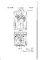
Fig. 1 is a front elevation of a casing housing a plurality of pressure gauges.
Fig. 2 is a top plan illustration of the casing and gauges shown in Fig. I.
Fig. 3 is an isometric illustration of a gauge embodying my invention with parts broken away to show the internal mechanism.
Fig. l is a fragmentary view, partially in section, of a detail shown in Fig. 3.
Fig. 5 is an isometric illustration in section, of a part of the mechanism shown in Fig. 3.
Fig. 6 illustrates a diaphragm assembly.
Fig. 7 is a fragmentary view to enlarged scale in cross section along the line 'l-I, in the direction of the arrows, of Fig. 6.
The embodiment of my invention I have chosen to illustrate is particularly adapted to the measurement of relatively small pressure differences in the order of a fraction to several inches of water or mercury. Such pressure difference may be that existing between the pressure of the atmosphere and the pressure within a confined region commonly termed, draft. pressure within the confined region is greater than that of the atmosphere it is known as a positive draft. When less than that of the atmosphere as a negative draft. Again the pres- [TED STATES PATENT OFFICE PRESSURE GAUGE Frederick A. Barnes, Cleveland Heights, Ohio, as-
signor to Bailey Meter Company, a corporation of Delaware Application .llune 10, 1937, Serial No. 147,524
sure difference may be that existing between two confined regions or the difierence existing between two points in the path of a flowing fluid. It will be apparent from the description to follow that my invention may be employed in the measurement of pressure difierences of a high order of magnitude and that the embodiment disclosed is merely illustrative and not limiting.
Referring to Figs. 1 and 2, I therein show a casing I in which is mounted a pressure responsive device generally indicated at 2 arranged to angularly position an index 3 relative to an arcuate scale t, which may he graduated in any desired units, such as inches of water, inches of mercury, or pounds per square inch. The device 2 may also be calibrated so that the index 3 travels over the scale t for any desired range in pressure differences, and so that the index 3 is positioned downwardly or upwardly for increasing or decreasing pressure differences as may be desired.
For example, increasing negative drafts may be indicated by downward positioning of the in dex, whereas increasing positive drafts may be indicated by upward positioning of the index. In the former case, at zero draft the index will be at the top of the scale and In the latter at the bottom. In other cases the draft may vary from a positive to a negative value, and vice versa, so that the zero position of the index lies between the extreme limits of the cooperating scale, which is preferably graduated to indicate both the magnitude of the drafts and whether positive or negative. For purposes of i1- lustration, however, I have shown the device 2 calibrated to position the index 3 downwardly or clockwise over the scale -'-l for a range in pressures from 0 to +0.5 inch of water.
It is frequently advantageous to indicate a plurali y of drafts or pressure differences at a central point. For example, in the operation of steam generators it is highly desirable that the operator be advised of the drafts existing at a plurality of points in the gas or air passages of the generator. Preferably such indications are all made at a centrally located point so that the relative magnitude of such drafts may readily be determined. ,The device 2 is readily adapted to battery mounting, and in Fig. 1 and Fig. 2 are shown devices 5, 6 and 1 similar to the device 2 arranged to angularly position indices 8, 9 and ill respectively.
In Fig. 3 I have shown the pressure responsive device 2 in isometric projection with parts broken away so the internal mechanism is illustrated.
joined by a horizontal base member 22.
Separated by a pressure sensitive diaphragm assembly generally indicated at I I are flanged pressure tight chambers I2 and I3. The chamber I3 is provided with a foot or pedestal I4 secured to the floor of the casing I and serving to support the device in position. The diaphragm II is supported in proper position by triangular shaped drive links l5 and I6, the former of which is pivotally carried at its outer end by a leaf or cantilever spring I1 and the latter of which is pivotally carried at its outer end by a member I8.
Pressures, the difference of which is to be measured, are admitted to the chambers l2 and I3 by pipes I9 and 20 respectively. Movements of the diaphragm I I due to the difference in pressure within the chambers I2 and I3 are opposed by the spring I I, so that for every pressure difierence there exists a definite position of the diaphragm II. For example, assuming that the pressure within the chamber I2 is greater than that within the chamber I3, then the diaphragm II will be positioned to the left (as viewed in the drawings) until the opposing force created by the flexing of the spring I is equal to the force created by the action of the pressure difference on the diaphragm II.
As shown in Fig. 4 the member I8 is symmetrical about its vertical axis and comprises laterally extending arms |9A and 28A terminating in upwardly extending pivot bearings which are Jour- .naled in the pivot bearings are pivots carried Secured to the member I8 between the arms I9A and 20A is a lever 24 passing through an opening in the wall of the chamber I3. Secured to the wall of the chamber I3 is a ring 25 to which is secured a flexible diaphragm 26 pressure sealing the opening in the wall while permitting the member I8 and shaft 24 to be positioned about the pivots 23. The diaphragm 26 is sealed pressure tight about the shaft 24 by means of a pliant washer 21 supported by the member 22 and held in firm engagement with the diaphragm 26 by a similar washer 28 forced downwardly by a cam wedge 29 pivoted to the member 24 by a screw 29A and engaging a cup shaped member 30. After the cam wedge 29 has been turned to the position shown, about screw 29A, a pin 3| is inserted through member 24 which prevents movement of the wedge.
The pivot bearings formed by arms |9A and 20A extend upwardly so that pivots 23 and 23A lie in the same plane as the center section of the diaphragm 26, avoiding undue flexing of the diaphragm due to angular positioning of the shaft 24. A counterweight 32 carried by the member I8 compensates for the weight of the shaft ,24 so that the center of gravity of the assembly coincides with the center line of the pivots 23 and 23A. Movements of the assembly away from the vertical accordingly do not cause a reaction on the diaphragm II and incorrect positioning of the index 3. v
The chamber I3 carries a bifurcated extension having arms 33 and 34 supporting pivot bearings 35 and 36 respectively. Pivoted in these bearings is a shaft 3'! to which is secured the index 3 and an arm 38 pivotally connected to the lever 24 by a link 39. The arm 38 is provided with a pivot bearing 38A on the opposite side of the shaft 31 than that to which the link 39 is pivoted. If link 39 is pivoted in bearing 38A then movement of diaphragm II to the left will produce downward or clockwise movement of index 3. Secured to the shaft 31 is a counterweight 40, so that the center of gravity of the entire assembly comprising the index 3 and arm 38 may be 7 brought to the longitudinal center line of the shaft 31. Similarly the link 39 is provided with a counterweight 4| so that its center of gravity may be brought to the pivot connection with the shaft 24. In this manner the entire moving mechanism is in static balance regardless of the position of the index 3 and varying reactions upon the diaphragm I I are eliminated. Accordingly, the sole reactive force on the diaphragm II is that due to the spring I! which, as hereinafter more fully explained, may be calibrated so that for every diiference in pressure existing across the diaphragm the index 3 may be brought to a predetermined desired position relative to the scale 4. I
As shown in Fig. 5 the spring I1 is secured I at its upper end to a cradle 42 pivotally mounted as indicated at 42A (Fig. 3) in the chamber I2 and urged against an adjustable stop 43 by a spring 44. With equal pressures existing within chambers I2 and I3 the index 3 may be moved relative to the scale 4 by adjustment of the stop 43, or theposition of the index 3 relative to the scale 4 may be varied for any pressure difference between chambers I2 and I3 by such adjustment. The range in pressure differences required to position the index 3 from one limit of the scale 4 to the other remains the same, however, regardless of the adjustment.
Within the cradle 42 is an open ended carriage 45 movable longitudinally by a screw 46 journaled in the cradle. The spring 2|| passes through the carriage 45 through suitable slots. Within the carriage is a hollow rectangular cupshaped member 41, one side of which engages the wall of the cradle 42 and the edges of which engage the spring I'I. On the opposite side of the spring I1 is a similar cup shaped member 48, the edges of which engage the spring. Lying adjacent the wall of the member 48 is a hollow triangular member 49 mating with a similar member 50, having a side engaging the wall of the cradle 42. Threaded into the triangular shaped member 50 is a manually adjustable screw 50A having a collar or thrust bearing 5| located between the upper wall of the carriage 45 and triangular shaped member 49. The screw 50A passes through the carriage 45 and member 49 through an enlarged opening; so that the member 49 is free to slide lateraaly with respect to the member 58. one direction tends to move the member 50 upwardly causing the member 49 to move to the right as viewed in the drawings, thereby locking cup shaped members 41 and 48 against the spring I1. The triangular shaped members 49 and 50 act in other words as an expanding member upon manipulation oi the screw 59A, locking the carriage 45 in the position it then occupies and causing the cup shaped members 41 and 48 to firmly engage the spring IT.
The position of the carriage 45 determines the free or effective length of the spring I1, and thereby controls or determines the rangein pressure differences required to position the index 3 from the minimum graduation on scale 4 to the maximum. For example, as the carriage 45 is positioned downwardly as shown in Fig. the
Rotation of the screw 50A in edect'ive length of the spring it decreases, thereby increasing opposition to movement of the diaphragm ii and requiring a greater range in pressure differences to position the index 3 from minimum to maximum position. Conversely as the carriage it is positioned upwardly, the effective length of the spring H is increased, thereby decreasing the range in pressure diflerences required to position the index 3 from, minimum to maximum position.
The carriage t5 and associated devices provide a simple and convenient means for calibrating the gauge. The index 3 is readily brought to the initial or starting position relative to the scale t by proper manipulation of the screw 43, and correct movement of the index 3 for a given range in pressure diderences is obtained through proper manipulation of the screw #6. Excepting the time when the screw 46 is being manipulated, the screw WA provides a convenient means for locking the carriage $5 in position and definitely setting or defining the effective length of the spring Ill. A cap 52 is provided which is secured to the v casing it after adjustment has been completed to prevent manipulation of screws t6 and A by unauthorized persons.
In Figs. 6 and II have illustrated in detail the pressure sensitive diaphragm assembly gen- The assembly is symmetrical about its longitudinal and transverse axes. Clamped between oblong shaped shrouding rings 53A and 53B is a pliant flexible pressure tight diaphragm 5t provided with sufficient slack so that it may be positioned in one direction or the other from the plane of the rings 53A and MB in accordance with the pressure difference existing between chambers l2 and i3. Interposed between the rings 53A and 53B and diaphragm 5d are gaskets 55A and 553. The rings 53A and 53B are provided with eyelets 5B for clamping the diaphragm 5t. As shown in Fig. 3 the assembly l l is clamped between the flanges of chambers it and it by suitable screws passing through the eyelets.
The diaphragm M is preferably composed of a flexible, pressure tight, yet relatively strong material having no internal resistance to flexing and impervious to acid, caustic, heat and other deleterious conditions to which it may be exposed. I have found that a suitable material is Japanese silk, which provides the strength and flexibility required, and that impregnating this material with a synthetic rubber compound, known under the trade name, Koroseal, renders it pressure tight and impervious to deleterious conditions while maintaining its inherent flexibility.
Covering the center section of the diaphragm Ml are flat plates 56A and MB having sharply upturned edges WA and MB respectively, defining the free area of the diaphragm M. I have found that it is desirable to maintain the free area of the diaphragm, that is the section of the diaphragm flexed under the influence of pressure within sharply defined limits and of relatively narrow width. In the assembly I have illustrated, the free area consists of the band of the diaphragm 5t lying between the inner edges of the rings 53A and 53B and the upturned edges MA and MB of plates 56A and 563. In this manner the effective area of the diaphragm throughout its range of movement is maintained constant so that equal changes in pressure differences result in equal movements of the index 3.
So that the edges WA and 573 will firmly clamp diaphragm 5t and hence sharply define its free area, I provide clamping plates 59A and 593.
The plate 59A has an upturned edge 6IA, an arc section 62A immediately adjacent thereto, and
a fiat center section 63A. The plate 593 is pro-.
vided with a similar upturned edge 6IB, arc section 623 and flat center section 63B. Plates 59A and 59B are clamped between the bases of drive links I5 and I 6 by studs 68 and 69 provided with suitable cooperating nuts.
In their normal unfiexed position the outer edges 6 IA and H3 extend beyond the center sections 63A and 63B, so that before the cooperating nuts or studs 68 and 69 are drawn up the center sections 63A and 633 do not engage plates 56A and 56B. Upon drawing up the cooperating nuts the edges MA and BIB are urged outwardly against edges 51A and 51B and downwardly against the fiat side of plates 56A and 563, thereby effectively clamping or holding the diaphragm 54 in predetermined position. The free area of the diaphragm 54 is also sharply defined, resulting in a predetermined effective area, remaining constant throughout the range of motion of the diaphragm. Such construction also facilitates duplication of the calibration between units, so that the characteristic of any particular gauge having a certain effective spring length may be readily predicted.
As hereinbefore stated, the drive links 15 and I6 support the diaphragm 54, thereby maintaining uniform slack throughout its free area. Accordingly, bunching or binding of the diaphragm at different points in its travel is avoided, and likewise movements of the drive links l5 and IE will be substantially perpendicular to the plane of the diaphragm, resulting in a consistant and uniform motion of the index 3.
While in accordance with the patent statutes I have illustrated and described a particular embodiment of my invention, it will be evident to those skilled in the art that it may be incorporated in various devices and is capable of different modifications. For example, the index 3 may be provided with suitable marking means so that it will give in addition to an indication of the difference in pressures existing between chambers l2 and I3 a permanent record of such difference.
Accordingly, the illustrated and described em bodiment should be taken as merely illustrative and not as limiting.
What I claim as new, and desire to secure by Letters Patent of the United States, is:
1. In a pressure responsive device, in combination, a cradle, a cantilever spring supported in said cradle, a pair of jaws for clamping said spring movable in said cradle along said spring, and means for urging said jaws against said spring.
2. In a pressure responsive device, in combination, a cradle, a cantilever spring secured to one end of said cradle and extending longitudinally thereof, a carriage in said cradle movable longitudinally thereof, said spring passing through said carriage, jaw members carried by said carriage' for clamping said spring. and means for urging said jaws against said spring.
ed in said carriage for urging said jaw members against said spring.
4. In a pressure responsive device, in combination, a cradle, pivoted means for positioning said cradle, a cantilever spring secured to the end of said cradle adjacent said pivots and extending longitudinally thereof, a carriage in said cradle and movable longitudinally thereof said spring passing through saidcarriage, a rectangular cup shaped jaw member'on either side of said spring, a pair of triangular shaped members lying adjacent one of said jaws, and means for moving said triangular shaped members relative to one another to urge said jaw members against said spring.
5. In a pressure responsive device, in combination, a vertically disposed diaphragm sensitive to the pressure, a horizontal beam secured to said diaphragm and extending transversely on either side thereof, a vertically disposed spring pivotally connected to one end of said beam for producing a displacement of said diaphragm in accordance with changes in the pressure extending at'right angles to said beam and forming a support therefor, and a vertically disposed member oscillatable about a fixed pivot extending at right angles to said beam pivotally connected to the other end of said beam and forming a second support therefor, whereby said diaphragm is supported and held in predetermined vertical position by said beam.
6. In a pressure responsive device, in combination, a pivot, a cradle supported on said pivot and positionable about said pivot, a cantilever spring secured to the end of said cradle adjacent said pivot and extending longitudinally thereof, an open ended carriage extending transversely in said cradle and movable longitudinally therein, said spring passing through said carriage, a rectangular cup shaped jaw member in said carriage between said spring and the wall of said carriage, a similar cup shaped jaw member in said carriage on the opposite side of said spring, a pair of triangular shaped members in said carriage between said last named jaw member and a wall of said cradle, and means for moving said triangular members relative to each other towedge said jaw members against said spring.
7. In a pressure responsive device, in combination, a pivot, a cradle supported on said pivot and positionable about said pivot, a leaf spring secured to the end of said cradle adjacent said pivot and extending longitudinally thereof, an
open ended carriage extending transversely in said cradle and movable longitudinally therein, said spring passing through said carriage, a rectangular cup shaped jaw member in said carriage between said spring and the wall of said carriage, a similar cup shaped jaw member in said carriage on the opposite side of said spring, a pair of triangular shaped members in said carriage between said last named jaw member and the wall of said cradle and forming expansible means for forcing said last named jaw member toward said spring.
8. In a pressure responsive device, in combination, a pair of pressure receiving chambers, a movable pressure sensitive diaphragm separating said chambers, a beam secured to said diaphragm and extending perpendicularly thereof into said chambers, a spring in one of said chambers pivotally connected to said beam and forming a support therefor, a shaft in the other of said chambers pivotally connected to said beam and forming a support therefor, said shaft extending through an opening in a wall of said chamber, a pivoted support for said shaft located at said opening, a pliant pressure tight shield between said shaft and said wall, and an indicator of the position of said diaphragm actuated by said shaft.
9. In a pressure responsive device, in combination, a movable pressure sensitive diaphragm, a beam secured to substantially the midpoint of saiddiaphragm and extending perpendicularly on either side thereof, a cantilever spring for opposing motion of said diaphragm connected to said beam on one side of said diaphragm and ex- -tending at right angles to said beam, a cradle for supporting said spring, a pivoted support for said crade, means for positioning said cradle about said support, a carriage in said cradle and movable longitudinally of said spring, a pair of jaws for clamping said spring carried by said carriage, manually operated means for urging said jaws against said spring and cradle to lock said carriage in position, a shaft pivotally connected to said beam on the opposite side of said diaphragm and extending at right angles to said beam, a pivoted support for said shaft, and an indicator of the position of said diaphragm actuated by said shaft.
10. In a pressure responsive device, in combination, a. calibrating element comprising a cantilever spring supported at one end, a pair of jaws movable longitudinally along said spring for varying the effective length thereof, means for moving said jaws longitudinally along said spring, and means for clamping said jaws against said spring when in any position relative to said spring. I
. FREDERICK A. BARNES.
Priority Applications (1)
| Application Number | Priority Date | Filing Date | Title |
|---|---|---|---|
| US147524A US2184163A (en) | 1937-06-10 | 1937-06-10 | Pressure gauge |
Applications Claiming Priority (1)
| Application Number | Priority Date | Filing Date | Title |
|---|---|---|---|
| US147524A US2184163A (en) | 1937-06-10 | 1937-06-10 | Pressure gauge |
Publications (1)
| Publication Number | Publication Date |
|---|---|
| US2184163A true US2184163A (en) | 1939-12-19 |
Family
ID=22521913
Family Applications (1)
| Application Number | Title | Priority Date | Filing Date |
|---|---|---|---|
| US147524A Expired - Lifetime US2184163A (en) | 1937-06-10 | 1937-06-10 | Pressure gauge |
Country Status (1)
| Country | Link |
|---|---|
| US (1) | US2184163A (en) |
Cited By (4)
| Publication number | Priority date | Publication date | Assignee | Title |
|---|---|---|---|---|
| US2441882A (en) * | 1943-04-20 | 1948-05-18 | Bristol Company | Seal for differential pressure apparatus |
| US2459931A (en) * | 1945-01-12 | 1949-01-25 | Edison Inc Thomas A | Pressure gauge |
| US2509644A (en) * | 1944-01-06 | 1950-05-30 | Yarnall Waring Co | Differential pressure gauge |
| US2642743A (en) * | 1947-03-18 | 1953-06-23 | Hermanny Heinrich | Instrument pointer actuating mechanism and adjustment |
-
1937
- 1937-06-10 US US147524A patent/US2184163A/en not_active Expired - Lifetime
Cited By (4)
| Publication number | Priority date | Publication date | Assignee | Title |
|---|---|---|---|---|
| US2441882A (en) * | 1943-04-20 | 1948-05-18 | Bristol Company | Seal for differential pressure apparatus |
| US2509644A (en) * | 1944-01-06 | 1950-05-30 | Yarnall Waring Co | Differential pressure gauge |
| US2459931A (en) * | 1945-01-12 | 1949-01-25 | Edison Inc Thomas A | Pressure gauge |
| US2642743A (en) * | 1947-03-18 | 1953-06-23 | Hermanny Heinrich | Instrument pointer actuating mechanism and adjustment |
Similar Documents
| Publication | Publication Date | Title |
|---|---|---|
| US2184163A (en) | Pressure gauge | |
| US2431200A (en) | Lever mounting arrangement for pressure responsive measuring instruments | |
| US2436451A (en) | Measuring instrument | |
| US2090160A (en) | Draft and pressure indicator | |
| US3095745A (en) | Differential pressure instrument | |
| US2662539A (en) | Fluid-counterbalanced force measuring device | |
| US2535202A (en) | Indicating, recording, and controlling apparatus | |
| US2808725A (en) | Differential pressure measuring apparatus | |
| US2199013A (en) | Pressure gauge | |
| US1661323A (en) | Method and apparatus for setting thermostats | |
| US2265045A (en) | Pressure gauge, and more particularly a barograph | |
| US2816444A (en) | Pressure sensitive apparatus | |
| US2286621A (en) | Pressure measuring apparatus | |
| US2339847A (en) | Pressure indicator | |
| US2530068A (en) | Barometer | |
| US2368905A (en) | Aneroid barometer movement | |
| US1893200A (en) | Pressure responsive device and diaphragm for use therein | |
| US1780141A (en) | Stress indicator and recorder | |
| US2652716A (en) | Apparatus for detecting leaks in vacuum systems | |
| US1933522A (en) | Tank gauge | |
| US2340395A (en) | Pressure responsive indicating instrument | |
| US2551212A (en) | Diaphragm pressure indicating instrument | |
| US3279254A (en) | Liquid level gauge | |
| US2277681A (en) | Pressure measuring instrument | |
| US2770247A (en) | Instruments |