US2183848A - Telephone system - Google Patents
Telephone system Download PDFInfo
- Publication number
- US2183848A US2183848A US103435A US10343536A US2183848A US 2183848 A US2183848 A US 2183848A US 103435 A US103435 A US 103435A US 10343536 A US10343536 A US 10343536A US 2183848 A US2183848 A US 2183848A
- Authority
- US
- United States
- Prior art keywords
- relay
- winding
- contacts
- station
- call
- Prior art date
- Legal status (The legal status is an assumption and is not a legal conclusion. Google has not performed a legal analysis and makes no representation as to the accuracy of the status listed.)
- Expired - Lifetime
Links
- 238000004804 winding Methods 0.000 description 79
- 230000005540 biological transmission Effects 0.000 description 4
- 230000000881 depressing effect Effects 0.000 description 3
- 230000000694 effects Effects 0.000 description 3
- 230000000977 initiatory effect Effects 0.000 description 3
- 230000001737 promoting effect Effects 0.000 description 2
- 239000004020 conductor Substances 0.000 description 1
Images

Classifications
-
- H—ELECTRICITY
- H04—ELECTRIC COMMUNICATION TECHNIQUE
- H04Q—SELECTING
- H04Q3/00—Selecting arrangements
- H04Q3/58—Arrangements providing connection between main exchange and sub-exchange or satellite
- H04Q3/62—Arrangements providing connection between main exchange and sub-exchange or satellite for connecting to private branch exchanges
- H04Q3/625—Arrangements in the private branch exchange
Definitions
- the invention obviates these conditions in that the initiating impulses for inquiry switching and for switching on to connected sub- 25 scribers lines are transmitted by different potentials operating upon differential relays and that the differential relay influenced by the potential applied only promotes the switching operations corresponding to the impulse received.
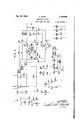
- FIG. 1 shows a call finder AS, a group selector GW, a final selector LW, and subscribers stations NI and N2 in a private branch exchange;
- Fig. 2 shows a trunk line AL from a public exchange terminating in an operators position BA located in the private branch exchange.
- a telephone private branch exchange system of the type disclosed in the drawings the transitory conimpulse transmitted from a station (operator) is only maintained, by a differential relay arranged in the feeding circuit, when a station entitled to switch on to engaged line applies negative-potential to the speaking line and 45 accordingly one particular winding of the differential relay in the feeding circuit of the calling station receives current.
- a local winding of this relay is connected up. This winding is connected in the same sense as the wind-.
- Subscribers NI and N2 are provided with earthing keys at their stations by means of which 55 impulses for promoting inquiry switchinggand er by depressing the key TaI.
- relay A energizes in the following feeding cir cuit: negative, winding I of relay A, winding I of relay Q, contacts 26M and 2'Ip-I, wiper s of the group selector GW,.wiper dot the call-finder AS, the loop of the station NI, wiper b of the call-finder AS, wiper b of the group selector 'GW, contacts 301, MM, winding'lI of relay Q, winding II of relay A and positive.
- RelayA opens contact 32a. The short-circuit for relay 0 is removed and this relay energizes. 1
- the final selector LW is set on the line of the desired station in the known manner (not represented). If the station N2 is free relay P is energized over: positive, contact 330, windings I and II of relay P, relay PI, wiper c, relay R2, relay T2, and neg- 35 ative. Relay P closes the following circuit for relay V: negative, contacts 3411, 35y, relayV, slow interrupter. LU, and positive. Ringing current is applied to the line atdefin'ite intervals of time.
- the ringing circuit passes from the source R of 0 ringing current over contacts 361), 31p, winding I of relay Y, contact 3810i, wiper a of the final selector LW, over thebell of the station N2, wiper b of the final selector LW, winding II of relay Y, contacts 9p and 391;, and positive.
- relay Y opens the circuit for relay V.
- Relay Z energizes over contact 48y and the switching through takes place at 492: and 502. 50
- the differential relay Q is. energized in his feeding circuit since cuit is completed: positive, contacts winding is, however, arranged in opposition to winding I of relay Q so that relay Q returns its contacts to normal.
- a repeated energizing and deenergizing of relay Q can take place as long as the subscriber depresses the key. During the depression of the key the speaking equipment of the station is short-circuited. When the subscriber releases the key relay Q releases and subscriber Ni is forced to bring about the release of the connection.
- the arrangement can also be so constructed so that relay Q only brings about the connection to an engaged line if the impulse for initiating such a connection is transmitted from the calling station within a strictly predetermined time, for example during the testing period of the selector.
- relay Q is energized but the opposing winding is switched on.
- Relay Q releases and the final selector is caused to release at the end of thetesting' period.
- the subscriber then receives the busy signal from the preceding connecting devices (for example over devices which are associated with the subscribers line).
- Relay AR When a call is received over the public exchange line AL relay AR is energized by the ringing current. In the case of calls over the public exchange line AL relay B2 is energized and remains so until the public exchange line is released.
- Relay AR closes the following circuit for relay M: positive, contact is, 2m, 311., winding II of relay M and negative.
- a call indicating lamp for the private branch exchange operator is switched on by relay AB in the known manner (not shown). The operator operates key AT and accordingly energizes relay AS.
- Relay AS closes contacts las and Bus so that the operators equipment BA is connected to the calling public exchange line AL.
- Relay VS When the operator has been told which subscriber is wanted she operates the key VT.
- Relay VS is energized.
- Relay VS opens contacts iBvs and iQus and closes contacts 2W8 and live.
- the equipment of the operator BA is accordingly connected over contacts Mas and 23cm to'the con necting side of the public exchange line AL.
- a calling circuit is closed over the loop of the operators position BA in the known manner and the call-finder AS is caused to be set on line iii/25. 'Ihereupon the relay RA energized over wiper c of the call finder AS.
- relay RA By means of relay RA relay T is energized over positive, contacts Em and 99b2, winding II of relay T and negative.
- Relay T causes relay U to energize over positive, contacts ldi, ilil, 5.2 iSui, and winding II of relay U.
- Relay U closes contact E la and thereby prepares the circuit for relay Ui.
- Relay T closes contact it".
- a circuit is completed for relay U over positive, contact 93b2, It, Winding I of relay U and negative.
- Relay U opens contact i iii and thereby removes the shortcircuit over relays U and III.
- winding I of relay U winding I of relay Ui
- wind- Relay Ui energizes, opens contact Hut and closes contact lfiiui. Relays U and Ui are now held energized over positive, contacts iilt and Mu, winding I of relay U, winding I of relay Ui, contact ifllui,
- Relay M is caused to release by the opening of contact Bu.
- Belay X is energized over positive,
- Relay X by opening contacts i702, prevents relay Xi from energizing.
- the operator transmits an impulse train and thereby sets the group selector GW on a free final selector LW.
- Relay C energizes. -.';I
- relay P energizes in the testing circuit of the selectorLW, over positive, contact 33c, windings I and II of relay P, relay Pl, wiper c of the final selector LW, relay R2, relay T2 and negative.
- relay P By means of relay P, relay V is connected up in a circuit influenced by the slow interrupter LU over negative, contacts S ip and 3521, relay V, slow interrupter LU and positive. Ringing current is applied to the line to be signalled at definite intervals of time by means of relay V.
- the ringing circuit passes from the source It of ringing current over contacts 36v and tip, Winding I of relay Y, contacts 382 i, wiper a of the final selector LW, over the bell at station N2, wiper b of the final selector LW, Winding II of relay Y, contacts 920, contact 3% and positive.
- relay Y at contact 35y breaks the circuit for relay V.
- the station N2 receives feeding current over the following circuit: negative, winding I of relay Bi, contacts 59vjand 3W, winding I of relay Y, contact 3321i, wiper a of the final selector LW, over the loop at station N2, wiper 'b. of the final selector LW, winding II of relay Y, contact $23, winding II of relay Bi and positive.
- the relay Bl arranged inthe feeding circuit is a differential relay which when connected in the foregoing circuit does not operate its contacts.
- Relay Y causes the following circuit to be established: positive, contacts 482/ and lla, wiper d of the group selector GW, wiper d of the call-finder AS, contacts 42m and 63M, winding I of relay M and negative. gizes; Over, contacts Hit and Wm, winding I of relay U and winding I of relay Ui are shortc'ircuited. Relay U opens contacts i iu'.
- RelayY at contact 65y completes a circuitfor relay Z.
- the circuit is completed over negative
- Relay Z switches through at contacts 492 and 502.
- Contact 4Iz breaks the circuit for relay M.
- the latter releases and at contacts I2m breaks the circuit for relay UI.
- Relay UI by opening contact IBuI returns relayU2 to normal.
- connection to the desired subscriber is established and the operator can switch off from the connection.
- Relays AS and VS thereupon deenergize and restore .their contacts to normal.
- the feeding bridge relay A is now held energized over the following circuit: negative, winding I of relay A, winding I of relay Q, contacts 28b4, 271ml, wiper a. of the group selector GW, wiper a of the call-finder A5,.
- winding II of relay X is connected in the same sense as winding I so that relay X remains energized.
- the operator can now transitorily apply battery to the line 24/25 in any desired way.
- the contact 5Ie may be the contact of a key which is operated by the operator after the transmission of a busy signal, or it can be automatic-ally closed after each impulse train when the operator, who is entitled to switch on to engaged lines, operates the impulse sender so that the.
- connection of battery need not take place at the station itself, but can take placein the exchange by using transmitting means.
- the transitory connection of battery causes the following circuit to be set up: negative, contacts 5Ie, ZIvs, 2211s, lead 25, wiper b of the callfinder AS, wiper b of the group selector GW, contacts 3019i and 3Ibl, winding II of relay Q, winding II of relay A and positive.
- the differential relay Q closes the following circuit over winding III of relay Q: positive, winding III of relay Q, contact 52: rotary oiI-normal contact 53w, contact 54p and negative.
- Winding III of relay Q is arranged in the same sense as winding II so that the relay remains energized after the transitory impulse and at contacts 55q and 56g effects the switching through in the final selector LW, independent of contacts 192 and 592. The operator is thus connected to the engaged subscriber N2 and can ask the latter to terminate his call.
- the subscriber of station N2 is thus connected with the calling public exchange line AL. v
- Relay XI closes contact 63.1.1.
- the following circuit is established: positive, contacts Hit and Ii IyI, winding I of relay ZI, contacts 63ml, 651:2 andGBuI, and negative.
- Relay ZI energizes and at contact GIzl prepares a circuit for relay YI.
- Relay ZI opens contacts 682I and Mel, and closes contacts 'IIlzI and 'IIzI. The public exchange connection is held over contact IBI'IeI.
- the differential relay BI in the feeding circuit releases-and contacts 6IlbI and 6IbI are opened and contacts ZIibI and 3Ibl are closed.
- Winding II of relay X receive-s current in the same direction as winding I of relay X.
- Relay X energizes.
- relay XI deenergizes.
- Contact 6311 is opened and thus the short-circuit over winding II of relay ZI and over winding I for relay YI is removed.
- the following circuit is established for relays ZI and YI: positive, contacts I51.
- Relay YI closes contact 'I'ZyI and opens contact 6411i.
- the following circuit iss-et up for relays Z! and YI: positive, contacts I51? and IfZyI, winding II of relay YI, winding II of relay ZI, winding I of relay YI, contacts B'IzI, 65u2, and 6BuI and negative.
- relay YI switches the inquiry linen/I5 through. Through the closingof contact 'ISyI' a calling circuit is closed inthe' known way and a free call-finder is set on the line Hi/I1. After the call finder has been set a circuit is established for relay RR over wiper c.
- the impulses transmitted from the station N2 for setting the switches of the inquiry path, are received by relay Y and transmitted to relay J by contact 18y.
- the circuit for relay J is as follows: positive, contacts 18y and I92, Wiper d of group selector GW, wiper d of call-finder AS,
- relay J breaks the loop of the inquiry line in correspondence with the impulse trains sent out so that the impulses are transmitted to the receiving devices'of the inquiry line.
- the group-selectorand final selector are set in the same way as has been described with reference to the group selector GW .and the final selector LW which are shown.
- the relay impulse is transmitted to winding I of relay M from the final selector set by the inquiry call over wiper d of v the group selector and call finder of the inquiry line, contacts 8011' and I'IuI, winding I of relay M and negative.
- 'Relay M is transitorily energized and locks up over positive contacts 9211.2, 841v, 85m and winding II of relay M and negative.
- Winding II of relay U is connected in the iii) relay U is arranged in the same sense as winding I of relay U so that relay U remains up.
- the subscriber called in the inquiry call is to take over the public exchange call he operates his earthing key transitorily and thereby energizes the difierential relay (see corresponding relay Bl) arranged in his feeding circuit.
- the differential relay effects a switching-over operation whereby the direction of the current in winding II of relay U i n the public exchange line is reversed.
- Relay U is accordingly deenergized and relay U is energized over positive, contacts Hit, Hit,
- Relay U operates and opens contacts 232a and 2911. and closes contacts 86a and 811i.
- the loop over the line 24/25 is accordingly broken and the connecting path which was set up from the operator to the desired station N2 is released.
- Relay U closes contact Mu.
- Relay U energizes again and opens contact Hit.
- the following circuit is established: positive, contacts Hit and Mu, winding I of relay U, winding I of relay Ul, contact l3ul, winding II of relay U and negative.
- Relay Ul opens contact 13ml and closes contact lfilul.
- the following circuit now exists for relays U and UI; positive, contacts Hit and Mu, winding I of relay U, winding I of relay Ul, contact llllul, Winding II of relay UI and negative.
- Relay Ul on energizing opens contact 66141 and thus breaks the locking circuit for relays Zl and Y.
- Relays Z and Yl return their contacts to normal.
- Relay U2 is energized over contacts lfiui.
- Relay U2 opens contacts 88u2, 89142, and closes contacts 3M2 and 9M2.
- Relay U2 opens contact 92u2.
- the locking circuit for relay M is broken so that this likewise returns its contacts to normal.
- the subscriber called in the inquiry call is now connected to the repeater Ue over line Iii/ll and contacts 8711. and 86a, and thus to the public exchange line AL.
- the following feeding circuit is established for the calling period: negative, Winding I of relay S, winding I of relay XI, lead 95, wiper a of group-selector GW, wiper a of call-finder AS, a loop at station Ni, wiper b of call-finder AS, wiper b of group selector GW, lead 94, winding II of relay Xi, contacts II of relay S and positive.
- this feeding circuit only relay S energizes.
- Relay Xi is differential relay and does not operate its contacts.
- On seizure the busy relay B2 of the pub lic exchange line is energized, in any desired manner.
- the following circuit is set upfor relay U: positive, contacts 93112 and It, winding I of relay U and negative.
- Relay U eifects the energizing of relay C! over positive, contacts lliZt and B11, relay Cl and negative.
- RelayX is energized over: negative, contact 9t, winding I of relay X and positive.
- Relay Cl connects the calling subscriber to the repeater Ue of the public exchange line by way of contacts 960! and Mel.
- Relay S switches through at contacts 98s.
- the subscriber can now transmit impulses over the public exchange line.
- the impulses are received by relay S and repeated to the public exchange line AL at contact 988.
- the subscriber called in the inquiry call can likewise take over the public exchange call. For this purpose he depresses his earthing key and thereby changes the direction of the current flowing in winding II of relay U which then in the manner already described causes the public exchange connection to be switched over onto the subscriber called in the inquiry call.
- automatic switches, subscribers stations and lines therefor means controlled by a subscriber at any one of said stations for extending a connection to any other one of said stations, an operators position, an incoming trunk line terminating at said position, means controlled by the operator at said position for controlling said switches to extend a call received over said trunk line to any one of said stations, means controlled from said operators position for controlling said switches to cut-in on a line of a station engaged in conversation and for enabling said switches to signal the station so engaged after the conversation has been terminated, means at the called station for temporarily holding the trunk line call and for extending a connection to any one of said subscribers stations, and means controlled at said other station for disconnecting said called station from said trunk line and for connecting said other station thereto.
- a first subscribers station in a telephone system, a first subscribers station, other subscribers stations, a trunk line, automatic switches controllable from said first station to extend a connection over said trunk line, other automatic switches, means controlled from said first station for holding the connection extended over said trunk line and for enabling the subscriber at said first station to control said other switches to extend a connection to one of said other stations, and means controlled from said second station for disconnecting said first station from the connection extended therefrom to said second station and to said trunk line and for completing a connectionbetween said second station and said trunk line.
- automatic switches in a telephone system, automatic switches, subscribers stations, an outgoing trunk line, means at any one of said stations for causing certain of said switches to be connected serially in a I train to extend a call from said one station to any other station or for causing certain of said switches to be connected serially inta train to extend an outgoing call from said one station over said trunk line, means controllable at said one station if an outgoing call has been extended over said trunk line for causing said outgoing call to be held while said trunk line is disconnected from the established connection and for causing said established connection to be extended to any other desired station over a train of said switches identical to said first train.
- automatic switches subscribers stations, means atany one of said stations for causing certain of said switches to be connected serially in a train to extend a call from said one station to any other desired station, an incoming trunk line, an ,operators position, means at said position for causing certain of said switches to be connected serially in a train to extend a call incoming over said trunk line to any of said stations, means at said posi tion for causing the switches of said last connection to cut-in upon the connection of a station engaged in conversation and for causing said coming trunk line, automatic switches, arepeater in said trunk line, means for extending a call incoming to the trunk-line side of said repeater through said repeater and a train of said switches to any desired local line, means controllable over the called line for disconnecting said trunk line from said trunk-line side of said repeater and for holding said incoming call while said trunk line is so disconnected, means controllable over said called line for extending a local call from said trunk-line side of said repeater to any desired
- a local exchange In a telephone system, a local exchange, local subscribers stations, a trunk line extending to a distant exchange, means in said, local exchange for establishing a voice transmission circuit between any one of said stations and said trunk line, a device in said local exchange for conductively isolating the trunk portion of said circuit from the local portion of said circuit,
Landscapes
- Physics & Mathematics (AREA)
- Astronomy & Astrophysics (AREA)
- General Physics & Mathematics (AREA)
- Engineering & Computer Science (AREA)
- Computer Networks & Wireless Communication (AREA)
- Interface Circuits In Exchanges (AREA)
Description
Dec. 19,1939 F. SIMON I TELEPHONE SYSTEM Filed Sept. 30, 1936 2 Sheets-Sheet 1 INVENTOR. FRANZ SIMON N\ a 3. N N N H 1 k E3? Jfilawi N E m \x Q m @m m MQF l m NM, \AWN N III .I ah d & 1 3 Ill .0 Qvm MW. v *WL L u. w Nu I 6 M s h mm .d a N f u J g 5? i Ag 1.: E a. fin H Q 1% & N $6 H NQW Ti 11% 8 m A'ITORNEY 40 meeting Patented Dec. 19, 1939 UNITED STATES PATENT OFFICE TELEPHONE SYSTEM Franz Simon, Berlin-Friedenau, Germany, as-
signor to Siemens 8: Halske Aktiengesellschaft, Siemensstadt, near Berlin, Germany Application September 30, 1936, Serial No. 103,435
In Germany October 1, 1935 15 Claims. (01. 179-27) subscribers stations possessing an earthing key.
Since, however, only privileged stations are to establish connection to engaged lines'while inquiry calls on the other hand can be promoted by some or all of the other subscribers who are not entitled to the former facility, separate connecting paths must be provided for those subscribers go entitled to establish connection toengaged lines,
andthose not so entitled. This, however, is uneconomical. The invention obviates these conditions in that the initiating impulses for inquiry switching and for switching on to connected sub- 25 scribers lines are transmitted by different potentials operating upon differential relays and that the differential relay influenced by the potential applied only promotes the switching operations corresponding to the impulse received.
30 One embodiment of the invention is shown in the drawings comprising Figs. 1 and 2, in which Fig. 1 shows a call finder AS, a group selector GW, a final selector LW, and subscribers stations NI and N2 in a private branch exchange; and
'35 Fig. 2 shows a trunk line AL from a public exchange terminating in an operators position BA located in the private branch exchange. In a telephone private branch exchange system of the type disclosed in the drawings the transitory conimpulse transmitted from a station (operator) is only maintained, by a differential relay arranged in the feeding circuit, when a station entitled to switch on to engaged line applies negative-potential to the speaking line and 45 accordingly one particular winding of the differential relay in the feeding circuit of the calling station receives current. In this case .a local winding of this relay is connected up. This winding is connected in the same sense as the wind-.
'50 ing operative in the feeding circuit so that the impulse promoting the switching on to an engaged line is maintained.
Subscribers NI and N2 are provided with earthing keys at their stations by means of which 55 impulses for promoting inquiry switchinggand er by depressing the key TaI.
for switching over to the devices of the exchange are transmitted. These subscribers who are not entitled to switching on to engaged calls can indeed influence the differential relay Q effecting the switching on operation by depressing their keys, but the winding III connected in the opposite sense to the operative winding I renders the impulse inoperative and thus prevents any connection taking place.
The switching operations will be described in detail as follows:
Internal calls If the subscriber of station NI wishes to converse with subscriber of station N2 he removes his receiver. The call-finder AS is thereby set on theline of the calling station in the known way.
A free final selector is seized over the group selector GW. When such a final'selector LW is found relay A energizes in the following feeding cir cuit: negative, winding I of relay A, winding I of relay Q, contacts 26M and 2'Ip-I, wiper s of the group selector GW,.wiper dot the call-finder AS, the loop of the station NI, wiper b of the call-finder AS, wiper b of the group selector 'GW, contacts 301, MM, winding'lI of relay Q, winding II of relay A and positive. RelayA opens contact 32a. The short-circuit for relay 0 is removed and this relay energizes. 1
Through the transmissionv of impulses the final selector LW is set on the line of the desired station in the known manner (not represented). If the station N2 is free relay P is energized over: positive, contact 330, windings I and II of relay P, relay PI, wiper c, relay R2, relay T2, and neg- 35 ative. Relay P closes the following circuit for relay V: negative, contacts 3411, 35y, relayV, slow interrupter. LU, and positive. Ringing current is applied to the line atdefin'ite intervals of time. The ringing circuit passes from the source R of 0 ringing current over contacts 361), 31p, winding I of relay Y, contact 3810i, wiper a of the final selector LW, over thebell of the station N2, wiper b of the final selector LW, winding II of relay Y, contacts 9p and 391;, and positive. When the subscriber replies by removing his receiver relay Y energizes. At contact 35y, relay Y opens the circuit for relay V. Relay Z energizes over contact 48y and the switching through takes place at 492: and 502. 50
If the subscriber is engaged and the calling party receives the busy signal in the known way he can try to switch'on to the engaged subscrib- The differential relay Q is. energized in his feeding circuit since cuit is completed: positive, contacts winding is, however, arranged in opposition to winding I of relay Q so that relay Q returns its contacts to normal. A repeated energizing and deenergizing of relay Q can take place as long as the subscriber depresses the key. During the depression of the key the speaking equipment of the station is short-circuited. When the subscriber releases the key relay Q releases and subscriber Ni is forced to bring about the release of the connection.
The arrangement can also be so constructed so that relay Q only brings about the connection to an engaged line if the impulse for initiating such a connection is transmitted from the calling station within a strictly predetermined time, for example during the testing period of the selector. Thus if the subscriber succeeds in connecting up earth at this particular time relay Q is energized but the opposing winding is switched on. Relay Q releases and the final selector is caused to release at the end of thetesting' period. The subscriber then receives the busy signal from the preceding connecting devices (for example over devices which are associated with the subscribers line).
Incoming public exchange calls When a call is received over the public exchange line AL relay AR is energized by the ringing current. In the case of calls over the public exchange line AL relay B2 is energized and remains so until the public exchange line is released. Relay AR closes the following circuit for relay M: positive, contact is, 2m, 311., winding II of relay M and negative. A call indicating lamp for the private branch exchange operator is switched on by relay AB in the known manner (not shown). The operator operates key AT and accordingly energizes relay AS. Relay AS closes contacts las and Bus so that the operators equipment BA is connected to the calling public exchange line AL.
When the operator has been told which subscriber is wanted she operates the key VT. Relay VS is energized. Relay VS opens contacts iBvs and iQus and closes contacts 2W8 and live. The equipment of the operator BA is accordingly connected over contacts Mas and 23cm to'the con necting side of the public exchange line AL. A calling circuit is closed over the loop of the operators position BA in the known manner and the call-finder AS is caused to be set on line iii/25. 'Ihereupon the relay RA energized over wiper c of the call finder AS.
By means of relay RA relay T is energized over positive, contacts Em and 99b2, winding II of relay T and negative. Relay T causes relay U to energize over positive, contacts ldi, ilil, 5.2 iSui, and winding II of relay U. Relay U closes contact E la and thereby prepares the circuit for relay Ui. Relay T closes contact it". A circuit is completed for relay U over positive, contact 93b2, It, Winding I of relay U and negative. Relay U opens contact i iii and thereby removes the shortcircuit over relays U and III. The following ciriilt, Mu,
ing II of relay U and negative.
winding I of relay U, winding I of relay Ui, wind- Relay Ui energizes, opens contact Hut and closes contact lfiiui. Relays U and Ui are now held energized over positive, contacts iilt and Mu, winding I of relay U, winding I of relay Ui, contact ifllui,
ing circuit is established for relay U2; positive, contact iiit, relay U2, contact iiiul and negative.
Relay M is caused to release by the opening of contact Bu. Belay X is energized over positive,
winding I of relay X, contact and negative, by
relay T. Relay X by opening contacts i702, prevents relay Xi from energizing. The operator transmits an impulse train and thereby sets the group selector GW on a free final selector LW.
When this has been done the following feeding circuit is established: negative, winding I of relay A, winding I of relay Q, contacts 2811i and 27211, wiper a of the group selector G'W, wiper a;
the short-circuit over relay C. Relay C energizes. -.';I
Impulse trains are transmitted from the operators position BA for setting the final selector LW. The setting of the final selector takes place in the known manner and is not represented.
If when the setting of the final selector on the station N2 required by the exchange is completed this station is found to be free relay P energizes in the testing circuit of the selectorLW, over positive, contact 33c, windings I and II of relay P, relay Pl, wiper c of the final selector LW, relay R2, relay T2 and negative. By means of relay P, relay V is connected up in a circuit influenced by the slow interrupter LU over negative, contacts S ip and 3521, relay V, slow interrupter LU and positive. Ringing current is applied to the line to be signalled at definite intervals of time by means of relay V. The ringing circuit passes from the source It of ringing current over contacts 36v and tip, Winding I of relay Y, contacts 382 i, wiper a of the final selector LW, over the bell at station N2, wiper b of the final selector LW, Winding II of relay Y, contacts 920, contact 3% and positive.
When the called subscriber replies relay Y energizes, relay Y at contact 35y breaks the circuit for relay V. The station N2 receives feeding current over the following circuit: negative, winding I of relay Bi, contacts 59vjand 3W, winding I of relay Y, contact 3321i, wiper a of the final selector LW, over the loop at station N2, wiper 'b. of the final selector LW, winding II of relay Y, contact $23, winding II of relay Bi and positive. The relay Bl arranged inthe feeding circuit is a differential relay which when connected in the foregoing circuit does not operate its contacts. Relay Y causes the following circuit to be established: positive, contacts 482/ and lla, wiper d of the group selector GW, wiper d of the call-finder AS, contacts 42m and 63M, winding I of relay M and negative. gizes; Over, contacts Hit and Wm, winding I of relay U and winding I of relay Ui are shortc'ircuited. Relay U opens contacts i iu'.
RelayY at contact 65y, completes a circuitfor relay Z. The circuit is completed over negative,
Relay M ener- 4.
winding II of relay U! and negative. The followiii) contacts 342) and 48y, relay Z and positive. Relay Z switches through at contacts 492 and 502. Contact 4Iz breaks the circuit for relay M. The latter releases and at contacts I2m breaks the circuit for relay UI. Relay UI by opening contact IBuI returns relayU2 to normal.
Thus the connection to the desired subscriber is established and the operator can switch off from the connection. Relays AS and VS thereupon deenergize and restore .their contacts to normal. The feeding bridge relay A is now held energized over the following circuit: negative, winding I of relay A, winding I of relay Q, contacts 28b4, 271ml, wiper a. of the group selector GW, wiper a of the call-finder A5,. lead 24, contacts 281a, winding I of repeater Ue, contact 58d, winding II of relay X, winding II of repeater Ue', contacts 58cm and 2%, lead 25, wiper b of the call-finder AS, wiper b of the group selector GW, contacts 3I3pi and 3Ibl, winding'II of relay Q, winding II of relay A and positive. In this circuit winding II of relay X is connected in the same sense as winding I so that relay X remains energized.
If the station N2 is engaged relay P cannot energize in the testing circuit of the final selector.
The operator can now transitorily apply battery to the line 24/25 in any desired way.
The contact 5Ie may be the contact of a key which is operated by the operator after the transmission of a busy signal, or it can be automatic-ally closed after each impulse train when the operator, who is entitled to switch on to engaged lines, operates the impulse sender so that the.
potential for causing connection to the engaged line is only applied during a particular period. The connection of battery need not take place at the station itself, but can take placein the exchange by using transmitting means.
The transitory connection of battery causes the following circuit to be set up: negative, contacts 5Ie, ZIvs, 2211s, lead 25, wiper b of the callfinder AS, wiper b of the group selector GW, contacts 3019i and 3Ibl, winding II of relay Q, winding II of relay A and positive. The differential relay Q closes the following circuit over winding III of relay Q: positive, winding III of relay Q, contact 52: rotary oiI-normal contact 53w, contact 54p and negative. Winding III of relay Q is arranged in the same sense as winding II so that the relay remains energized after the transitory impulse and at contacts 55q and 56g effects the switching through in the final selector LW, independent of contacts 192 and 592. The operator is thus connected to the engaged subscriber N2 and can ask the latter to terminate his call.
When the subscriber at station N2 finishes his call and the connection established is released the guarding is removed in the known way and. the testing relay P in the final selector LW can energize. The subscriber is rung in the known way. When he replies relay Y energizes and effects the switching operations already described (transmission of the reply impulse to the devices of the public exchange line). In addition switching through is caused in the manner described at contacts 492 and 502. When relay P energizes contact 512p is opened and the locking circuit for relay Q over winding III is disconnected. Relay Q releases.
The subscriber of station N2 is thus connected with the calling public exchange line AL. v
While a public exchange call is in progress the subscriber can establish an inquiry call. The
initiating impulse for establishing this inquiry call is given by the subscriber N2 by transitorily depressing his earthing key. By operating the key Ta2 the differential relay BI in the feeding circuit of the call station N2 is energized. By the closing of contacts 94bI and 95bI anyinfiuencing of the differential relay Q is prevented. Relay BI openscontacts 26bl and 3IbI, and closes contacts GObI and IiIbI. The circuit described for relay A is thereby switched over in such a way that winding II of relay X receives current in the opposite direction and acordingly causes relay X to release Relay X completes a circuit for relay XI over positive, contacts 6225 and Ilx; winding III of relay XI and negative. Relay XI closes contact 63.1.1. The following circuit is established: positive, contacts Hit and Ii IyI, winding I of relay ZI, contacts 63ml, 651:2 andGBuI, and negative. Relay ZI energizes and at contact GIzl prepares a circuit for relay YI. Relay ZI opens contacts 682I and Mel, and closes contacts 'IIlzI and 'IIzI. The public exchange connection is held over contact IBI'IeI.
When the subscriber at station N2 releases the key Ta2, the differential relay BI in the feeding circuit releases-and contacts 6IlbI and 6IbI are opened and contacts ZIibI and 3Ibl are closed. Winding II of relay X receive-s current in the same direction as winding I of relay X. Relay X energizes. On account of the operation of relay X, relay XI deenergizes. Contact 6311 is opened and thus the short-circuit over winding II of relay ZI and over winding I for relay YI is removed. The following circuit is established for relays ZI and YI: positive, contacts I51. and 6411i, windings I and II of relay ZI, winding I of relay YI, contacts 6'Izl, 6511.2 and (iouI and negative. Relay YI closes contact 'I'ZyI and opens contact 6411i. The following circuit iss-et up for relays Z! and YI: positive, contacts I51? and IfZyI, winding II of relay YI, winding II of relay ZI, winding I of relay YI, contacts B'IzI, 65u2, and 6BuI and negative. At contact ISyI relay YI switches the inquiry linen/I5 through. Through the closingof contact 'ISyI' a calling circuit is closed inthe' known way and a free call-finder is set on the line Hi/I1. After the call finder has been set a circuit is established for relay RR over wiper c.
The impulses transmitted from the station N2 for setting the switches of the inquiry path, are received by relay Y and transmitted to relay J by contact 18y. The circuit for relay J is as follows: positive, contacts 18y and I92, Wiper d of group selector GW, wiper d of call-finder AS,
contacts 42m, and 83uI, winding I of relay J and negative. At contact 827' relay J breaks the loop of the inquiry line in correspondence with the impulse trains sent out so that the impulses are transmitted to the receiving devices'of the inquiry line. The group-selectorand final selector are set in the same way as has been described with reference to the group selector GW .and the final selector LW which are shown. When the subscriber replies, the relay impulse is transmitted to winding I of relay M from the final selector set by the inquiry call over wiper d of v the group selector and call finder of the inquiry line, contacts 8011' and I'IuI, winding I of relay M and negative. 'Relay M is transitorily energized and locks up over positive contacts 9211.2, 841v, 85m and winding II of relay M and negative.
bridge of the inquiry line thus' winding 11 of RelayM closes contacts lfim and opens 146m. Winding II of relay U is connected in the iii) relay U is arranged in the same sense as winding I of relay U so that relay U remains up.
If the subscriber called in the inquiry call is to take over the public exchange call he operates his earthing key transitorily and thereby energizes the difierential relay (see corresponding relay Bl) arranged in his feeding circuit. The differential relay effects a switching-over operation whereby the direction of the current in winding II of relay U i n the public exchange line is reversed. Relay U is accordingly deenergized and relay U is energized over positive, contacts Hit, Hit, |2m and l3ul, winding II of relay U and negative. Relay U operates and opens contacts 232a and 2911. and closes contacts 86a and 811i. The loop over the line 24/25 is accordingly broken and the connecting path which was set up from the operator to the desired station N2 is released.
Relay U closes contact Mu. When the subscriber called in the inquiry call releases the key the direction of the current through winding II of relay U is reversed again. Relay U energizes again and opens contact Hit. The following circuit is established: positive, contacts Hit and Mu, winding I of relay U, winding I of relay Ul, contact l3ul, winding II of relay U and negative. Relay Ul opens contact 13ml and closes contact lfilul. The following circuit now exists for relays U and UI; positive, contacts Hit and Mu, winding I of relay U, winding I of relay Ul, contact llllul, Winding II of relay UI and negative. Relay Ul on energizing opens contact 66141 and thus breaks the locking circuit for relays Zl and Y. Relays Z and Yl return their contacts to normal. Relay U2 is energized over contacts lfiui. Relay U2 opens contacts 88u2, 89142, and closes contacts 3M2 and 9M2. Relay U2 opens contact 92u2. The locking circuit for relay M is broken so that this likewise returns its contacts to normal. The subscriber called in the inquiry call is now connected to the repeater Ue over line Iii/ll and contacts 8711. and 86a, and thus to the public exchange line AL.
Establishment of an outgoing public exchange call If a subscriber for example at station NI desires an outgoing public exchange call, then after removing the receiver and setting the call-finder AS, he has to set the groupselector on a particular contact level in which a free public exchange line can be reached. If the group-selector GW is set on line B l/d5 relay T energizes over wiper c of the group selector GW. The following feeding circuit is established for the calling period: negative, Winding I of relay S, winding I of relay XI, lead 95, wiper a of group-selector GW, wiper a of call-finder AS, a loop at station Ni, wiper b of call-finder AS, wiper b of group selector GW, lead 94, winding II of relay Xi, contacts II of relay S and positive. In this feeding circuit only relay S energizes. Relay Xi is differential relay and does not operate its contacts. On seizure the busy relay B2 of the pub lic exchange line is energized, in any desired manner. The following circuit is set upfor relay U: positive, contacts 93112 and It, winding I of relay U and negative. Relay U eifects the energizing of relay C! over positive, contacts lliZt and B11, relay Cl and negative. RelayX is energized over: negative, contact 9t, winding I of relay X and positive. Relay Cl connects the calling subscriber to the repeater Ue of the public exchange line by way of contacts 960! and Mel.
Relay S switches through at contacts 98s. The subscriber can now transmit impulses over the public exchange line. The impulses are received by relay S and repeated to the public exchange line AL at contact 988.
If a subscriber who has set up an outgoing public exchange call desires to establish an inquiry call he transitorily depresses the earth key Ta! and thereby energizes the differential relay X! in his feeding circuit. Relay Xi influences relays Zl and Y! in the manner already described. The line is switched over onto the inquiry line Hi/"i5. The switching operations subsequently occurring are exactly the same as already described.
The subscriber called in the inquiry call can likewise take over the public exchange call. For this purpose he depresses his earthing key and thereby changes the direction of the current flowing in winding II of relay U which then in the manner already described causes the public exchange connection to be switched over onto the subscriber called in the inquiry call.
What is claimed is:
1. In a telephone system, automatic switches, subscribers stations and lines therefor, means controlled by a subscriber at any one of said stations for extending a connection to any other one of said stations, an operators position, an incoming trunk line terminating at said position, means controlled by the operator at said position for controlling said switches to extend a call received over said trunk line to any one of said stations, means controlled from said operators position for controlling said switches to cut-in on a line of a station engaged in conversation and for enabling said switches to signal the station so engaged after the conversation has been terminated, means at the called station for temporarily holding the trunk line call and for extending a connection to any one of said subscribers stations, and means controlled at said other station for disconnecting said called station from said trunk line and for connecting said other station thereto.
2. In a telephone system, automatic switches, subscribers stations and lines therefor, an operators position, an incoming trunk line, means con-- trolled by the operator at said position for controlling said switches to extend a call received over said trunk line toany one of said stations, a first differential relay, means at said operators position for energizing said difierential relay to control said switches to cut-in on a line engaged in conversation, a second differential relay, and means at the called subscribers station for controlling said second diiferential relay to enable said called subscriber to hold said trunk call while he extends an inquiry call to another one of said stations.
3. In a telephone system, automatic switches, subscribers stations and lines therefor, an operators position, an incoming trunk line, means controlled by the operator at said position for controlling said switches to extend a call received over said trunk line to any one of said stations, a first differential relay, means at said operators position for energizing said differential relay to control said switches to cut-in on a line engaged in conversation, a second differential relay, means at the called subscribers station for controlling said second differential relay to enable said called subscriber to hold said trunk call while he extends an inquiry call to another one of said stations, a third difierential relay, and means at the subscribers station to which said inquiry call has been extended for energizing said third differential. relay to disconnect the first of said called subscribers stations from said inquiry call and from said trunk call and for connecting said trunk call to the subscribers station to which the inquiry call has been extended,
4. A telephone system as claimed in claim 3, in which the second and third difierential relays are energized from a ground potential applied by means of a key at the subscribers stations and the first of said differential relays is energized from a negative potential applied from said operators position.
5. A telephone system as claimed in claim 3, in which said diiferential relays are connected to the talking conductors of the extended connections.
6. In a telephone system, a first subscribers station, other subscribers stations, a trunk line, automatic switches controllable from said first station to extend a connection over said trunk line, other automatic switches, means controlled from said first station for holding the connection extended over said trunk line and for enabling the subscriber at said first station to control said other switches to extend a connection to one of said other stations, and means controlled from said second station for disconnecting said first station from the connection extended therefrom to said second station and to said trunk line and for completing a connectionbetween said second station and said trunk line.
7. In a telephone system, automatic switches, subscribers stations, an outgoing trunk line, means at any one of said stations for causing certain of said switches to be connected serially in a I train to extend a call from said one station to any other station or for causing certain of said switches to be connected serially inta train to extend an outgoing call from said one station over said trunk line, means controllable at said one station if an outgoing call has been extended over said trunk line for causing said outgoing call to be held while said trunk line is disconnected from the established connection and for causing said established connection to be extended to any other desired station over a train of said switches identical to said first train.
8. In a telephone system such as claimed in claim 7, means controllable at said last station for disconnecting said last station from said one station and for connecting said last station to said trunk line to take over said outgoing call.
9. In a telephone system, automatic switches, subscribers stations, an incoming trunk line, means for causing certain of said switches to be :onnected serially in a train to extend a call in- :oming over said trunk line to any of said stations, means at the calledstation for causing a local extension to replace said trunk line in the established connection and for causing said incoming call to be held while said trunk line is disconnected from said established connection, means at said called station for directing said ocal extension through a train of switches identical to said first train to any other one of said stations.
10. In a telephone system such as claimed in claim 9, means controllable at said other station for disconnecting said other station from said called station and for connecting said other station to said trunk line to take over said incoming call.
11. In a telephone system, automatic switches, subscribers stations, means atany one of said stations for causing certain of said switches to be connected serially in a train to extend a call from said one station to any other desired station, an incoming trunk line, an ,operators position, means at said position for causing certain of said switches to be connected serially in a train to extend a call incoming over said trunk line to any of said stations, means at said posi tion for causing the switches of said last connection to cut-in upon the connection of a station engaged in conversation and for causing said coming trunk line, automatic switches, arepeater in said trunk line, means for extending a call incoming to the trunk-line side of said repeater through said repeater and a train of said switches to any desired local line, means controllable over the called line for disconnecting said trunk line from said trunk-line side of said repeater and for holding said incoming call while said trunk line is so disconnected, means controllable over said called line for extending a local call from said trunk-line side of said repeater to any desired other one'of said local lines over a train of said switches identical to said first train.
13. In a telephone system, a local exchange, local subscribers stations, a trunk line extending to a distant exchange, means in said, local exchange for establishing a voice transmission circuit between any one of said stations and said trunk line, a device in said local exchange for conductively isolating the trunk portion of said circuit from the local portion of said circuit,
means controllable at said one station for dis-' connecting the trunk line from the trunk side.
of said device and for placing a holding bridge across said trunk line, means controllable at said one station for extending a local voice transmission circuit to any other one of said stations from said trunk side of said device, means controllable at said other station for causing the circuit to said one stationto be disconnected from the local side of said device, for causing the circuit to said other station to be disconnected from the trunk side of said device and connected to said local side of said device, and for causing said trunk line to be disconnected from said holding bridge and reconnected to said trunk side ofsaid device.
14. In a telephone system, subscribers stations and lines therefor, an incoming trunk line, an operators position, automatic switches, said switches effective at times to extend a local call from any one of said stations to any other station under control of a subscriber at said one station and eiiective at other times to extend a' call incoming over said trunk line to any one of said stations under control of the operator at said position, a diiferential relay in one of said switches connected in the line circuit of the said first potential to said line circuit of said position, said relay efiective' responsive only to said last potential to cause said switches both to cut-in upon the line of a station engaged in another call and to signal the station so engaged ,5
when said other call is terminated.
FRANZ SIMON.
Applications Claiming Priority (1)
| Application Number | Priority Date | Filing Date | Title |
|---|---|---|---|
| DE2183848X | 1935-10-01 |
Publications (1)
| Publication Number | Publication Date |
|---|---|
| US2183848A true US2183848A (en) | 1939-12-19 |
Family
ID=7989007
Family Applications (1)
| Application Number | Title | Priority Date | Filing Date |
|---|---|---|---|
| US103435A Expired - Lifetime US2183848A (en) | 1935-10-01 | 1936-09-30 | Telephone system |
Country Status (1)
| Country | Link |
|---|---|
| US (1) | US2183848A (en) |
-
1936
- 1936-09-30 US US103435A patent/US2183848A/en not_active Expired - Lifetime
Similar Documents
| Publication | Publication Date | Title |
|---|---|---|
| US2543022A (en) | Metering circuit control for automatic telephone systems | |
| US2183848A (en) | Telephone system | |
| US2398854A (en) | Telephone system | |
| US2247507A (en) | Telephone system | |
| US1864553A (en) | Telephone system | |
| US2609456A (en) | Rotary out-trunk switching arrangement | |
| US2020816A (en) | Automatic telephone system | |
| US1763161A (en) | Telephone system | |
| US2339669A (en) | Communication system | |
| US3320367A (en) | Telephone line circuit | |
| US1857827A (en) | Telephone system | |
| US1753334A (en) | Telephone system | |
| US2188520A (en) | Party line telephone system | |
| US1930921A (en) | Telephone system | |
| US2744160A (en) | Circuit arrangement for pulse controlled telephone systems | |
| US1927531A (en) | Telephone system | |
| US2483206A (en) | Transmission of tone to warn the operator of a momentary disablement of a telephone talking connection by a coin collector | |
| US1753491A (en) | Automatic telephone system | |
| US2564084A (en) | Telephone system having repeater insertion on long distance lines | |
| US2836660A (en) | Interoffice trunking in telephone systems | |
| US3003040A (en) | Modified trunk circuit | |
| US2426196A (en) | Automatic telephone system | |
| US2284329A (en) | Telephone system | |
| US2209777A (en) | Telephone system | |
| USRE17703E (en) | ne ab beblin |