US2181982A - Variable high frequency transformer - Google Patents
Variable high frequency transformer Download PDFInfo
- Publication number
- US2181982A US2181982A US210982A US21098238A US2181982A US 2181982 A US2181982 A US 2181982A US 210982 A US210982 A US 210982A US 21098238 A US21098238 A US 21098238A US 2181982 A US2181982 A US 2181982A
- Authority
- US
- United States
- Prior art keywords
- frequency transformer
- intermediate frequency
- support
- inductance
- variable
- Prior art date
- Legal status (The legal status is an assumption and is not a legal conclusion. Google has not performed a legal analysis and makes no representation as to the accuracy of the status listed.)
- Expired - Lifetime
Links
Images

Classifications
-
- H—ELECTRICITY
- H03—ELECTRONIC CIRCUITRY
- H03H—IMPEDANCE NETWORKS, e.g. RESONANT CIRCUITS; RESONATORS
- H03H7/00—Multiple-port networks comprising only passive electrical elements as network components
- H03H7/01—Frequency selective two-port networks
- H03H7/0153—Electrical filters; Controlling thereof
- H03H7/0161—Bandpass filters
- H03H7/0169—Intermediate frequency filters
- H03H7/0176—Intermediate frequency filters witout magnetic core
Definitions
- This invention relates to improvements in intermediate frequency transformers for variable inductance tuning in a superheterodyne radio receiver, and has for its main object the elimina 5 tion ofthe disadvantages known in the usual transformers.
- intermediate frequency transformers are usually tuned by means of a variable condenser of the mica type. This result is obtained by means of an adjusting screw which increases or reduces the pressure applied on the metal sheets forming the condenser element.
- the mica is placed between the sheets to act as a dielectric. This mica condenser varies in capacity from around 50 to 120 mmfd.
- the inductance associated with the tuned circuit has a fixed value.
- the mechanical jerks alter the setting of the adjusting screw, which in turn increases or reduces the capacity of the condenser.
- the changes in temperature cause the expansion and contraction of the elements forming the mica variable condenser, with a resulting change in capaclty.
- the action is different.
- the air charged with humidity may actually deposit small particles of water between the condenser sheets and thus change the dielectric constant of the dielectric material.
- the increase in capacity due to humidity may be as high as per cent. This means a change of up to 7 percent. in the frequency at which the intermediate frequency transformer is tuned. If the resonance frequency is 390 kc., then the change reaches to around 30 kc. Changes of this order not only alter the reading of the dial of a radio receiver but also mean a loss in sensibility and selectivity due to misalignment.
- a fixed impregnated mica condenser which, due to its construction and processing, is not subject to the limitations outlined above for the variable mica type. and the tuning is effected by adjusting the inductance, which is variable.
- the disadvantages associated with the common type of mica variable condenser are obviated.
- the construction and treatment are such that the 55 variable inductance units cannot change with me-- typev of intermediate frequency transformer, all
- the usual intermediate frequency transformer consists of two tuned circuits which are coupled together by inductive of capacitative coupling, or both.
- the inductance associated with the tuned circuit is formed of two or more parts. The inductance value of the two or more coils in series is adjusted by varying the space between the sections. This varies the mutual inductance between the sections, and therefore the inductance associated with the tuned circuit.
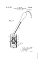
- Figure 1 is a circuit diagram of an intermediate frequency transformer according to the present invention
- FIG. 2 is a perspective view of the intermediate frequency transformer made in accordance with my invention.
- Figure 3 shows a physical arrangement indicating the method used in the construction of this 25 type of intermediate frequency transformer.
- LI and L2 are the sections of the transformer primary, shown in two halves,
- m indicating the mutual inductance between said two halves.
- This m is variable, and is adjusted to the correct value so as to tune the circuit Li and L2 and C to resonance.
- the inductance value associated with the tuned circuit is equal to Ll +L2 +2m.
- M The mutual between the two tuned circuits, primary andsecondary, respectively, is indicated by M. This value is fixed and only varies slightly with the variation of m. M is designed to give the required selectivity and gain.
- L2 and L3 are wound on a paper tube or sleeve 4, with a fixed defined distance between both. This 4 distance determines the mutual M between the two tuned circuits.
- the condensers C are'also placed in position on this same paper sleeve in this particular, construction.
- Ll is wound on paper tube or sleeve 5, and L4 on paper tube or sleeve 3.
- These three winding units 3, 4 and 5 are supported by a paper tube 2.
- the diameters of 'tube 2, and sleeves 3, 4 and 5 are such that sleeves 3 and 5 easily move on the tubular sup- 50 port 2 when no thermo-plastic impregnating compound is present ln these tubes or,when such compound is heated to a point where it becomes plastic or in fluid condition.
- the diameter of the sleeve 4 is such that it cannot move very easily 5 on the tube 2 "under the conditions indicated alcove for the sleeves t and 55.
- a heating device 85 is inserted into the open end of support tube 2 through an aligned end opening in the housing it and the upper portion of the intermediate frequency transformer.
- thermo plastic impregnating compound When the thermo plastic impregnating compound has reached a semi-fluid condition,
- the heating device is withdrawn.
- a pointed adjusting tool v is inserted humidity will not alter the setting of Li and LG relative to L2 and L3, respectively.
- thermo-plastic means securing one of said sections on said support in spaced relation to another of said sections, a housing surrounding said support and forming therewith an enclosure for said coils,
- a tubular coil support In a tuned intermediate frequency transformer, a tubular coil support, primary and secondary inductance coils axially arranged on said support and including a plurality of spaced coil sections respectively, a second tubular snip port concentricaly arranged along said first named support for supporting the adjacent seo- -tions of said primary and secondary coil strucsurface of said first named tubular support for softening said thermo-plastic means whereby at least one of said more remote sections may be relatively adjusted along said first named support to adjust the self-inductance oi the corresponding coil.
- means including other sleeves and thermo-plastic material for securing more remote sections of said primary and sec-.
Description
Dec. 5, 1939.
S. TARZIAN VARIABLE HIGH FREQUENCY TRANSFORMER Filed May 51, 1938 2 Sheets-Sheet l 3nventor Ila/n,
dttorneg Dec; 5, 1939 Y 'sv TARZI N 2,181,982
VARIABLE HIGH FREQUENCY TRANSFORMER Filed May 31, lss 2 Sheets-Sheet 2 Bnventor Garlies Tarzpan i I attorney Patented Dec. 5, 1939 UNITED STATES VARIABLE HIGH FREQUENCY TRANS- FORMER Sarkes Tarzian, Bnenos Aires, Argentina, assign-- or to Radio Corporation of America, a corporation of Delaware Application May 31, 1938, Serial No. 210,982 In Argentina November 12, 1937 4 Claims.
I This invention relates to improvements in intermediate frequency transformers for variable inductance tuning in a superheterodyne radio receiver, and has for its main object the elimina 5 tion ofthe disadvantages known in the usual transformers.
In less expensive radio receivers, intermediate frequency transformers are usually tuned by means of a variable condenser of the mica type. This result is obtained by means of an adjusting screw which increases or reduces the pressure applied on the metal sheets forming the condenser element. The mica is placed between the sheets to act as a dielectric. This mica condenser varies in capacity from around 50 to 120 mmfd. The inductance associated with the tuned circuit has a fixed value.
Due to the nature of the mica variable condens er, the capacity thereof, and therefore the tuning of the intermediate frequency transformer, changes with mechanical jerks and vibrations, as well as changes in tgnperature and humidity.
The mechanical jerks alter the setting of the adjusting screw, which in turn increases or reduces the capacity of the condenser. The changes in temperaturecause the expansion and contraction of the elements forming the mica variable condenser, with a resulting change in capaclty.
In the case of humidity the action is different. The air charged with humidity may actually deposit small particles of water between the condenser sheets and thus change the dielectric constant of the dielectric material. Under conditions of high humidity, the increase in capacity due to humidity may be as high as per cent. This means a change of up to 7 percent. in the frequency at which the intermediate frequency transformer is tuned. If the resonance frequency is 390 kc., then the change reaches to around 30 kc. Changes of this order not only alter the reading of the dial of a radio receiver but also mean a loss in sensibility and selectivity due to misalignment.
According to the present invention, a fixed impregnated mica condenser is used which, due to its construction and processing, is not subject to the limitations outlined above for the variable mica type. and the tuning is effected by adjusting the inductance, which is variable. In this the disadvantages associated with the common type of mica variable condenser are obviated. The construction and treatment are such that the 55 variable inductance units cannot change with me-- typev of intermediate frequency transformer, all
chanical vibrations or normal changes in temperature and/or humidity. The usual intermediate frequency transformer consists of two tuned circuits which are coupled together by inductive of capacitative coupling, or both. In the type according to the present invention, the inductance associated with the tuned circuit is formed of two or more parts. The inductance value of the two or more coils in series is adjusted by varying the space between the sections. This varies the mutual inductance between the sections, and therefore the inductance associated with the tuned circuit.
In order that the invention may be more carefully understood and readily carried into practice, the same has been illustrated in a preferred embodiment in the accompanying drawings. wherein Figure 1 is a circuit diagram of an intermediate frequency transformer according to the present invention,
Figure 2 is a perspective view of the intermediate frequency transformer made in accordance with my invention, and
Figure 3 shows a physical arrangement indicating the method used in the construction of this 25 type of intermediate frequency transformer.
Referring to Fig. 1, LI and L2 are the sections of the transformer primary, shown in two halves,
m indicating the mutual inductance between said two halves. This m is variable, and is adjusted to the correct value so as to tune the circuit Li and L2 and C to resonance. The inductance value associated with the tuned circuit is equal to Ll +L2 +2m. The mutual between the two tuned circuits, primary andsecondary, respectively, is indicated by M. This value is fixed and only varies slightly with the variation of m. M is designed to give the required selectivity and gain. L2 and L3 are wound on a paper tube or sleeve 4, with a fixed defined distance between both. This 4 distance determines the mutual M between the two tuned circuits. The condensers C are'also placed in position on this same paper sleeve in this particular, construction. Ll is wound on paper tube or sleeve 5, and L4 on paper tube or sleeve 3. These three winding units 3, 4 and 5 are supported by a paper tube 2. The diameters of 'tube 2, and sleeves 3, 4 and 5 are such that sleeves 3 and 5 easily move on the tubular sup- 50 port 2 when no thermo-plastic impregnating compound is present ln these tubes or,when such compound is heated to a point where it becomes plastic or in fluid condition. The diameter of the sleeve 4 is such that it cannot move very easily 5 on the tube 2 "under the conditions indicated alcove for the sleeves t and 55. After assembling the va-= ious parts forming the complete intermediate frequency transformer as illustrated in 1'6 g. 2, the entire unit is submerged in an impregnating compound. This will remove all the humidity, etc, from the coils and paper tubes. When the intermediate frequency transformer is withdrawn from the impregnating tank, a sufdcient impregnating compound should be left on the coils and paper tubes to seal them against humidity and also to render it impossible, when the impregnating com pound has been cooled down to room temperature, to move the coil Ll with respect to L2, andthe coil L3 with respect to L 1,
Fig. 3 -.illustrates an intermediate frequency transformer within its housing ill, which also serves as an electric shield, adapted to be mount= ed on a radio" chassis. To tune the intermediate frequency transformer to resonance it is desirable to proceed in the iollovrlng manner:
(a) A heating device 85 is inserted into the open end of support tube 2 through an aligned end opening in the housing it and the upper portion of the intermediate frequency transformer.
(b) When the thermo plastic impregnating compound has reached a semi-fluid condition,
the heating device is withdrawn.
(0) A pointed adjusting tool v is inserted humidity will not alter the setting of Li and LG relative to L2 and L3, respectively.
I claim as my invention:
1. In a high frequency transformer, a tubular coil support, a plurality of inductance coil sections axially positioned along said support in concentric relation therewith, thermo-plastic means securing one of said sections on said support in spaced relation to another of said sections, a housing surrounding said support and forming therewith an enclosure for said coils,
amines said. support and said housing having aligned openings at one end, respectively, tor the applica= tion oi heat within said tubular support to soften said thermo-plastic means, and an orifice in said housing provided adjacent said one section for the insertion of a tool to adjust the relative posi tion of said one of said coil sections along said support.
2. In a tuned intermediate frequency transformer, a tubular coil support, primary and secondary inductance coils axially arranged on said support and including a plurality of spaced coil sections respectively, a second tubular snip port concentricaly arranged along said first named support for supporting the adjacent seo- -tions of said primary and secondary coil strucsurface of said first named tubular support for softening said thermo-plastic means whereby at least one of said more remote sections may be relatively adjusted along said first named support to adjust the self-inductance oi the corresponding coil.
3. in a tuned intermediate frequency trans former, a tubular coil support, primary and secondary inductance coil sections axially arranged along said support in spaced, relation, a sleeve on said support carrying the adjacent coil sec tions of said primary and secondary, respectively,
in fixed coupling relation, means including other sleeves and thermo-plastic material for securing more remote sections of said primary and sec-.
,ondary coils, respectively, to said first named SARIES TARZIAN.
Applications Claiming Priority (1)
| Application Number | Priority Date | Filing Date | Title |
|---|---|---|---|
| AR2181982X | 1937-11-12 |
Publications (1)
| Publication Number | Publication Date |
|---|---|
| US2181982A true US2181982A (en) | 1939-12-05 |
Family
ID=3461597
Family Applications (1)
| Application Number | Title | Priority Date | Filing Date |
|---|---|---|---|
| US210982A Expired - Lifetime US2181982A (en) | 1937-11-12 | 1938-05-31 | Variable high frequency transformer |
Country Status (1)
| Country | Link |
|---|---|
| US (1) | US2181982A (en) |
Cited By (3)
| Publication number | Priority date | Publication date | Assignee | Title |
|---|---|---|---|---|
| US2544508A (en) * | 1948-03-26 | 1951-03-06 | Rca Corp | Signal transfer apparatus |
| US2729795A (en) * | 1945-09-19 | 1956-01-03 | Conrad H Hoeppner | Delay line |
| US3876915A (en) * | 1973-09-07 | 1975-04-08 | Precision Paper Tube Co | Electrical coil form with capacitor-holding means |
-
1938
- 1938-05-31 US US210982A patent/US2181982A/en not_active Expired - Lifetime
Cited By (3)
| Publication number | Priority date | Publication date | Assignee | Title |
|---|---|---|---|---|
| US2729795A (en) * | 1945-09-19 | 1956-01-03 | Conrad H Hoeppner | Delay line |
| US2544508A (en) * | 1948-03-26 | 1951-03-06 | Rca Corp | Signal transfer apparatus |
| US3876915A (en) * | 1973-09-07 | 1975-04-08 | Precision Paper Tube Co | Electrical coil form with capacitor-holding means |
Similar Documents
| Publication | Publication Date | Title |
|---|---|---|
| US2251085A (en) | Short electromagnetic wave oscillatory circuit | |
| US2435630A (en) | Tuned transformer assembly | |
| US2181982A (en) | Variable high frequency transformer | |
| US2051012A (en) | Permeability tuning means | |
| GB633397A (en) | Improvements in automatic radio tuning systems | |
| US2364291A (en) | Intermediate frequency transformer | |
| US2263613A (en) | Unicontrol variable inductance tuning system | |
| US2441116A (en) | Wide-band high-frequency transformer | |
| US2165575A (en) | High-frequency coupling device | |
| US2227487A (en) | Concentric line coupling | |
| US2190082A (en) | Permeability-tuned superheterodyne receiver | |
| US2452560A (en) | Band-pass transformer | |
| US2111373A (en) | Permeability-tuned device | |
| US1978600A (en) | Permeability-tuned resonant circuit | |
| US4255728A (en) | Parallel resonant electric circuit | |
| US2158255A (en) | Permeability-tuned intermediatefrequency transformer | |
| US2144029A (en) | High frequency coupling device | |
| US2447002A (en) | Permeability tuned intermediate frequency transformer | |
| US2458071A (en) | Adjustable inductor | |
| US2989630A (en) | Tuning apparatus | |
| US2310797A (en) | Frequency variation compensation circuit | |
| US2283926A (en) | Coupling method and apparatus | |
| US2145371A (en) | Oscillator coil system for low frequency bands | |
| US2066777A (en) | Coupling system | |
| US1936438A (en) | Coupling means |