US218066A - Improvement in electric oil-testers - Google Patents
Improvement in electric oil-testers Download PDFInfo
- Publication number
- US218066A US218066A US218066DA US218066A US 218066 A US218066 A US 218066A US 218066D A US218066D A US 218066DA US 218066 A US218066 A US 218066A
- Authority
- US
- United States
- Prior art keywords
- oil
- cup
- wires
- test
- fire
- Prior art date
- Legal status (The legal status is an assumption and is not a legal conclusion. Google has not performed a legal analysis and makes no representation as to the accuracy of the status listed.)
- Expired - Lifetime
Links
- 239000003921 oil Substances 0.000 description 33
- XLYOFNOQVPJJNP-UHFFFAOYSA-N water Substances O XLYOFNOQVPJJNP-UHFFFAOYSA-N 0.000 description 9
- 238000010438 heat treatment Methods 0.000 description 5
- 238000000034 method Methods 0.000 description 4
- 238000010276 construction Methods 0.000 description 3
- 239000003208 petroleum Substances 0.000 description 2
- 229920001875 Ebonite Polymers 0.000 description 1
- 108091023288 HOTAIR Proteins 0.000 description 1
- 239000003795 chemical substances by application Substances 0.000 description 1
- 238000004891 communication Methods 0.000 description 1
- 239000004020 conductor Substances 0.000 description 1
- 238000010892 electric spark Methods 0.000 description 1
- 230000005611 electricity Effects 0.000 description 1
- 239000007788 liquid Substances 0.000 description 1
- 239000002245 particle Substances 0.000 description 1
- 230000000630 rising effect Effects 0.000 description 1
Images

Classifications
-
- G—PHYSICS
- G01—MEASURING; TESTING
- G01N—INVESTIGATING OR ANALYSING MATERIALS BY DETERMINING THEIR CHEMICAL OR PHYSICAL PROPERTIES
- G01N25/00—Investigating or analyzing materials by the use of thermal means
- G01N25/50—Investigating or analyzing materials by the use of thermal means by investigating flash-point; by investigating explosibility
- G01N25/52—Investigating or analyzing materials by the use of thermal means by investigating flash-point; by investigating explosibility by determining flash-point of liquids
Definitions
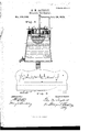
- Figure 1 is a perspective view of my apparatus 5 Fig. 2, a cross-sectional view of the reservoir-bath and the oil-cup; Fig. 3. a rear view, showing one arrangement of the wires leading from the battery to the cup.
- A is a table to support the apparatus; B, a back to the same, sustaining the electrical conducting-wires; G, the reservoir to contain water for heating the oil-cup; D, a lamp for heating the water in reservoir 0; E, a small bar or platform (made of hard rubber, in practice) to sustain the pivoted ends G G of the conducting-wires; F, a thermometer, to indicate the heat of the oil.
- G G G G G G are the pivoted ends of the conducting-wires; H, a key; I, an induction-coil; J, a switch.
- K K are the batteries.
- L is an oil-cup, held suspended in the reservoir or bath 0.
- g g g are the points at which the conductor ends of wires G G, &c., are pivoted to the main wires.
- M and N are the two electric points (positive and negative) for producing the spark. They pass, respectively, from the pivoted ends G G through the non-conducting rubber bar E, almost meeting beneath it, and immediately above the surface of the oil in cup L.
- O P R S T U U V W are wires leading from the battery to the coil I and wires G G G G G G G G G G".
- the operation is as follows: The reservoirO is first partially (nearly wholly) filled with hot water at a temperature of about 100 Fahrenheit. The oil to be tested is then placed in cup L, which is nearly filled. Now, as I wish to test the oil in that particular cup to ascertain its fire-test, I turn the switch-handle J to the middle point, 2.
- the pivoted ends G G G are connected with the induction-coil by wires W, U, and U, and the induction-coil is connected with the battery-jar K by means of wire P.
- the jars ofthe battery are connected by a wire between them.
- the switch-pivot is connected with the induction-coil by means of wire V.
- the wire 0 passes from the induction-coil to the key H.
- This key is also connected with the battery-jar K by means of wire 0.
- the circuit between wires 0 and O is broken by the key when the latter is open, and the circuit is closed when the key is shut.
- the points 1, 2, and 3 of the switch J are connected with pivoted ends G G G", respectively, by the wires S, T, and B, respectively, the wire V being attached to the pivot of switch J, so that as the handle of switch J is moved to any one of points 1, 2, or 3, a current of electricity shoots through that point and the Wires connected with it.
- the switch if is, as mentioned above and as shown in the drawings, turned to point 2, which completes a circuit from the pivot of the switch to the point 2.
- the cup L filled with oil
- the said water being at 100 Fahrenheit
- the oil will rapidly rise in temperature to nearly or about 94 Fahrenheit, and this may possibly be the temperature at which it will burn, so it is tested at that temperature. indicate its temperature, as the bulb of this thermometer rests in the oil, as shown iii Fig. 2.
- wires G G and wires Gr and G" may be connected with other cups and reservoirs, electric communication with which can be established by means of switch J and its points 1, 2, and 3 in the same manner as is above described with regard to cup L, and the number of points 1, 2, and 3 and cups L and reservoir 0 may be increased to any desired extent, the whole being managed by a single operator stationed at the key Il. AS each cup increases in heat he can continuously apply his tire-test, thus determining the test of each cup of oil in succession.
- my cup L hasits cylindrical portion or body carried up above the surrounding flange or rim,upon which it rests in reservoir 0.
- This construction is to prevent any water which may be upon the top of reservoir (J from running into the cup; to facilitate measuring the quantity of oil which I wish to placein the cup, as I generally fill my cup to a point much higher than shown in the drawings, in fact nearly upto the upper edge of the cup; and it also prevents the oil, from capillary attraction, working up onto the greasy rim or flange.
- a hotair chamber may be set between the water and the cup L, or a hot-air chamber may be used alone; but in the latter case the heat would not be so uniform as when one of the other methods above described is used.
- My apparatus is applicable to petroleum and all kinds of oils, and to the products of petroleum, naphtha, and analogous liquids ortluids.
- the cupsin which oil is tested, as described above, are very small, and, from their slight bulk, the oil is easily susceptible to the influences of whatever in the shape of tire, flame, or heat is brought near to it.
- an electrical apparatus so arranged thatan electrical spark from the apparatusflashcs the vaporof the oil, whereby the tirc-test of the latter is determined, and a switch, J, and key H, whereby two or more cups of oil heating at the same time may be tested successively by simply turning the switch and operating the key, substantially as described.
Landscapes
- Physics & Mathematics (AREA)
- Health & Medical Sciences (AREA)
- Life Sciences & Earth Sciences (AREA)
- Chemical & Material Sciences (AREA)
- Analytical Chemistry (AREA)
- Biochemistry (AREA)
- General Health & Medical Sciences (AREA)
- General Physics & Mathematics (AREA)
- Immunology (AREA)
- Pathology (AREA)
- Investigating Or Analyzing Materials Using Thermal Means (AREA)
Description
No. 218,066. Patented July 29,1879.
Fig.1
rLPETERs, FNDTO-LITHOGRAFHER. WASHINGTON. u C.
' ZSheets-Sheii GQM. SAYBOLT, Electric Oil-Tester.
him 218,066. atnte July 29,1879.-
Fl 3 Atiesis InveYfl/or UNITED STATES PATENT OFFICE.
GEORGE M. SAYBOLT, OF PHILADELPHIA, PENNSYLVANIA, ASSIGNOR TO LOOKWOOD BROTHERS 81; HOLLY, OF NEW YORK, N. Y.
IMPROVEMENT IN ELECTRIC OIL-TESTERS.
Specification forming part of Letters Patent No. 218,066, dated July 29, 1879; application filed April 14, 1879.
To all whom it may concern:
Be it known that I, GEORGE M. SAYBOLT, of Philadelphia, State of Pennsylvania, have invented certain new and useful Improvements in Oil-Testers; and I do hereby declare the following to be a full, clear, and exact description of the same, reference being had to the annexed drawings, making part hereof.
The nature of my invention will be fully shownin the followingspecification and claims.
In order to enable others skilled in the art to make and use the same, I will describe its construction and mode of operation.
In the drawings, Figure 1 is a perspective view of my apparatus 5 Fig. 2, a cross-sectional view of the reservoir-bath and the oil-cup; Fig. 3. a rear view, showing one arrangement of the wires leading from the battery to the cup.
A is a table to support the apparatus; B, a back to the same, sustaining the electrical conducting-wires; G, the reservoir to contain water for heating the oil-cup; D, a lamp for heating the water in reservoir 0; E, a small bar or platform (made of hard rubber, in practice) to sustain the pivoted ends G G of the conducting-wires; F, a thermometer, to indicate the heat of the oil. G G G G G G are the pivoted ends of the conducting-wires; H, a key; I, an induction-coil; J, a switch. K K are the batteries. L is an oil-cup, held suspended in the reservoir or bath 0. g g g are the points at which the conductor ends of wires G G G, &c., are pivoted to the main wires. M and N are the two electric points (positive and negative) for producing the spark. They pass, respectively, from the pivoted ends G G through the non-conducting rubber bar E, almost meeting beneath it, and immediately above the surface of the oil in cup L. O P R S T U U V W are wires leading from the battery to the coil I and wires G G G G G G".
The operation is as follows: The reservoirO is first partially (nearly wholly) filled with hot water at a temperature of about 100 Fahrenheit. The oil to be tested is then placed in cup L, which is nearly filled. Now, as I wish to test the oil in that particular cup to ascertain its fire-test, I turn the switch-handle J to the middle point, 2. The pivoted ends G G G are connected with the induction-coil by wires W, U, and U, and the induction-coil is connected with the battery-jar K by means of wire P. The jars ofthe battery are connected by a wire between them. The switch-pivot is connected with the induction-coil by means of wire V. The wire 0 passes from the induction-coil to the key H. This key is also connected with the battery-jar K by means of wire 0. The circuit between wires 0 and O is broken by the key when the latter is open, and the circuit is closed when the key is shut. Now, the points 1, 2, and 3 of the switch J are connected with pivoted ends G G G", respectively, by the wires S, T, and B, respectively, the wire V being attached to the pivot of switch J, so that as the handle of switch J is moved to any one of points 1, 2, or 3, a current of electricity shoots through that point and the Wires connected with it. Now, the battery K K being in operation, and it being desired to apply a spark at intervals to the cup L to as certain its fire-test, the switch if is, as mentioned above and as shown in the drawings, turned to point 2, which completes a circuit from the pivot of the switch to the point 2. When the cup L, filled with oil, is placed in the bath of water in reservoir 0, the said water being at 100 Fahrenheit, the oil will rapidly rise in temperature to nearly or about 94 Fahrenheit, and this may possibly be the temperature at which it will burn, so it is tested at that temperature. indicate its temperature, as the bulb of this thermometer rests in the oil, as shown iii Fig. 2. I now close the circuit of my electrical apparatus by touching and bearing down upon key H, which causes a spark to flash between the points M and N, Fig. 2. As a vapor or gas is constantly rising from the surface of the oil as it is heated, the spark will set fire to or flash ofl" this gas. If the oil is at such a temperature that it will burn'in contact with fire, this flash will set fireto the oil, and the temperature at which this burningoccurs will be its fire-test. If it does not burn at this test, the lamp D is lighted; which heats the water, (whose temperature. is determined by the thermometer F,) and the water in turn The thermometer 13 will heats up the oil. As the oil becomes more highly heated, the sparks from points M N are repeated until the vapor or gaseous flashes set fire to it, when the temperature is immediately noted upon thermometer F, and the fire-test is thus determined.
As the wires G G are connected with cup L and reservoirt, so wires G G and wires Gr and G" may be connected with other cups and reservoirs, electric communication with which can be established by means of switch J and its points 1, 2, and 3 in the same manner as is above described with regard to cup L, and the number of points 1, 2, and 3 and cups L and reservoir 0 may be increased to any desired extent, the whole being managed by a single operator stationed at the key Il. AS each cup increases in heat he can continuously apply his tire-test, thus determining the test of each cup of oil in succession.
It will be noticed that my cup L hasits cylindrical portion or body carried up above the surrounding flange or rim,upon which it rests in reservoir 0. This construction is to prevent any water which may be upon the top of reservoir (J from running into the cup; to facilitate measuring the quantity of oil which I wish to placein the cup, as I generally fill my cup to a point much higher than shown in the drawings, in fact nearly upto the upper edge of the cup; and it also prevents the oil, from capillary attraction, working up onto the greasy rim or flange.
I purpose applying for Letters Patent upon this construction of cup in a separate application, as also upon the conical shape of my reservoirshown in Fig. 2, whiehshows thefrnsturn of a cone.
I do not limit myself to the precise form of apparatus shown, as any one skilled in the art can see that it is capable of much variation.
Instead of the reservoir shown at U, a hotair chamber may be set between the water and the cup L, or a hot-air chamber may be used alone; but in the latter case the heat would not be so uniform as when one of the other methods above described is used.
All these methods are equivalent modes of obtaining the same result-viz., the heating of the oil.
My apparatus is applicable to petroleum and all kinds of oils, and to the products of petroleum, naphtha, and analogous liquids ortluids.
The cupsin which oil is tested, as described above, are very small, and, from their slight bulk, the oil is easily susceptible to the influences of whatever in the shape of tire, flame, or heat is brought near to it.
By the old process of waving a flame over the surface of the oil to ignite the vapor, that surface was undoubtedly heated up; and as it is well known that the heated particles of oil will remain at the top, it follows that the temperature at the top of the oil was greater than that at the bottom, and really greater than the temperature indicated by the thermometer; and as the oil would ignite at its test-heat at the surface, it would catch fire at a temperature not indicated, and the test would be really valueless. Again, the approach of the large flame would not only heat the surface of the oil, but would heat the vapors also, so that they would flash more readily and sooner than was desired. In fact, the flame used to test the oil was a heat-producing agent in itself, and so rendered the test comparatively valueless because of heating the oil at the surface, while the bulb of the thermometer is sunk into the body of the oil.
By my invention an electric spark is flashed through the vapor at intervals, and with such rapidity as to haveno practical influence upon the oil itself. This is the great advantage of my invention over previous methods, while at the same time the rapidityand ease with which one man can make these tests also recommend it.
Having thus described my invention, what I claim as new, and desire to secure by Letters Patent, isv 1. In combination with the cup L and reservoir (J of an oil fire-tester, an electrical apparatus so arranged that an electrical spark from the apparatus flashes the vapor of the oil, whereby the fire-test of the latter is determined, substantially as described.
2. In combination with the cup Land reservoirU of an oil fire-tester, an electrical apparatus so arranged thatan electrical spark from the apparatusflashcs the vaporof the oil, whereby the tirc-test of the latter is determined, and a switch, J, and key H, whereby two or more cups of oil heating at the same time may be tested successively by simply turning the switch and operating the key, substantially as described.
GEO. M. SAYBOLT.
Witnesses:
GEORGE E. BUoKLEY, HENRY V. BUoKLEY.
Publications (1)
| Publication Number | Publication Date |
|---|---|
| US218066A true US218066A (en) | 1879-07-29 |
Family
ID=2287468
Family Applications (1)
| Application Number | Title | Priority Date | Filing Date |
|---|---|---|---|
| US218066D Expired - Lifetime US218066A (en) | Improvement in electric oil-testers |
Country Status (1)
| Country | Link |
|---|---|
| US (1) | US218066A (en) |
Cited By (1)
| Publication number | Priority date | Publication date | Assignee | Title |
|---|---|---|---|---|
| US2682765A (en) * | 1951-07-31 | 1954-07-06 | Union Oil Co | Microflash tester |
-
0
- US US218066D patent/US218066A/en not_active Expired - Lifetime
Cited By (1)
| Publication number | Priority date | Publication date | Assignee | Title |
|---|---|---|---|---|
| US2682765A (en) * | 1951-07-31 | 1954-07-06 | Union Oil Co | Microflash tester |
Similar Documents
| Publication | Publication Date | Title |
|---|---|---|
| US2057431A (en) | Method of making resistance elements | |
| US1994331A (en) | Apparatus for evaporating liquids | |
| US1801538A (en) | Incensz bttbweb | |
| US1381500A (en) | Electric wax-heater | |
| US1754574A (en) | Electric device for cooking food or the like | |
| US1963345A (en) | Wick lighter | |
| US2434825A (en) | Incense vaporizer adapted for use as a cigar lighter | |
| US1583600A (en) | Means for testing oil | |
| US1360387A (en) | Illuminating device | |
| US1979501A (en) | Cooking device | |
| US2269337A (en) | Thermoelectric generator and burner therefor | |
| Alexeev et al. | First naphthometers to determine the flash point of liquids: I. Open cup devices | |
| US165612A (en) | Improvement in automatic vapor-tests for hydrocarbons | |
| US1361689A (en) | Ignition device | |
| US997467A (en) | Electric cooker. | |
| US1343134A (en) | Electric water-heater | |
| US1901271A (en) | Liquid fuel burner | |
| US3096640A (en) | Simple apparatus for the detection of low boiling hydrocarbons by sparkgap method | |
| US1622797A (en) | Oil burner | |
| US1699610A (en) | Electric heating and cooking appliance | |
| US2515641A (en) | Electrically heated plate | |
| US1293507A (en) | Flare. | |
| US1136360A (en) | Calorimeter. | |
| US1410566A (en) | Best available co | |
| US2201708A (en) | Oil flash tester |