US2152114A - Dust separator - Google Patents
Dust separator Download PDFInfo
- Publication number
- US2152114A US2152114A US72400A US7240036A US2152114A US 2152114 A US2152114 A US 2152114A US 72400 A US72400 A US 72400A US 7240036 A US7240036 A US 7240036A US 2152114 A US2152114 A US 2152114A
- Authority
- US
- United States
- Prior art keywords
- dust
- casing
- cyclone
- gas
- opening
- Prior art date
- Legal status (The legal status is an assumption and is not a legal conclusion. Google has not performed a legal analysis and makes no representation as to the accuracy of the status listed.)
- Expired - Lifetime
Links
- 239000000428 dust Substances 0.000 title description 54
- 239000007789 gas Substances 0.000 description 47
- 238000010276 construction Methods 0.000 description 10
- 238000010586 diagram Methods 0.000 description 4
- 230000009471 action Effects 0.000 description 3
- 230000000694 effects Effects 0.000 description 3
- 230000008901 benefit Effects 0.000 description 2
- 238000004140 cleaning Methods 0.000 description 2
- 230000007423 decrease Effects 0.000 description 2
- 239000002245 particle Substances 0.000 description 2
- JTJMJGYZQZDUJJ-UHFFFAOYSA-N phencyclidine Chemical class C1CCCCN1C1(C=2C=CC=CC=2)CCCCC1 JTJMJGYZQZDUJJ-UHFFFAOYSA-N 0.000 description 2
- 238000010408 sweeping Methods 0.000 description 2
- 230000004075 alteration Effects 0.000 description 1
- 230000015572 biosynthetic process Effects 0.000 description 1
- 239000002131 composite material Substances 0.000 description 1
- 239000012141 concentrate Substances 0.000 description 1
- 230000003247 decreasing effect Effects 0.000 description 1
- 239000003546 flue gas Substances 0.000 description 1
- 239000000463 material Substances 0.000 description 1
- 230000009467 reduction Effects 0.000 description 1
- 230000000630 rising effect Effects 0.000 description 1
- 238000000926 separation method Methods 0.000 description 1
Images


Classifications
-
- B—PERFORMING OPERATIONS; TRANSPORTING
- B04—CENTRIFUGAL APPARATUS OR MACHINES FOR CARRYING-OUT PHYSICAL OR CHEMICAL PROCESSES
- B04C—APPARATUS USING FREE VORTEX FLOW, e.g. CYCLONES
- B04C1/00—Apparatus in which the main direction of flow follows a flat spiral ; so-called flat cyclones or vortex chambers
-
- B—PERFORMING OPERATIONS; TRANSPORTING
- B04—CENTRIFUGAL APPARATUS OR MACHINES FOR CARRYING-OUT PHYSICAL OR CHEMICAL PROCESSES
- B04C—APPARATUS USING FREE VORTEX FLOW, e.g. CYCLONES
- B04C3/00—Apparatus in which the axial direction of the vortex flow following a screw-thread type line remains unchanged ; Devices in which one of the two discharge ducts returns centrally through the vortex chamber, a reverse-flow vortex being prevented by bulkheads in the central discharge duct
- B04C3/04—Multiple arrangement thereof
-
- B—PERFORMING OPERATIONS; TRANSPORTING
- B04—CENTRIFUGAL APPARATUS OR MACHINES FOR CARRYING-OUT PHYSICAL OR CHEMICAL PROCESSES
- B04C—APPARATUS USING FREE VORTEX FLOW, e.g. CYCLONES
- B04C5/00—Apparatus in which the axial direction of the vortex is reversed
- B04C5/24—Multiple arrangement thereof
- B04C5/30—Recirculation constructions in or with cyclones which accomplish a partial recirculation of the medium, e.g. by means of conduits
-
- B—PERFORMING OPERATIONS; TRANSPORTING
- B04—CENTRIFUGAL APPARATUS OR MACHINES FOR CARRYING-OUT PHYSICAL OR CHEMICAL PROCESSES
- B04C—APPARATUS USING FREE VORTEX FLOW, e.g. CYCLONES
- B04C7/00—Apparatus not provided for in group B04C1/00, B04C3/00, or B04C5/00; Multiple arrangements not provided for in one of the groups B04C1/00, B04C3/00, or B04C5/00; Combinations of apparatus covered by two or more of the groups B04C1/00, B04C3/00, or B04C5/00
Definitions
- the object of the present 15 invention is the same as set forth in my aforesaid prior patent; viz., to provide apparatus for utilizing the double eddy current set up by a current of air or gas traveling a curved path, to assist in removing dust and other foreign matter 20 from the air or gas.
- the present application is directed to apparatus as illustrated and described in my aforesaid application, but not specifically illustrated, described nor claimed in my aforesaid patent, and in this connection a more specific object of the present invention is to provide, in dust removing apparatus of the cyclone type, novel and practical means for utilization of the double eddy current existent in such ap- 30 paratus as a material aid in the rapid and emcient removal of dust and other foreign matter from air or gas passing through the apparatus.
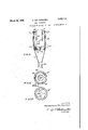
- Figure 1 is a vertical section through a dust removing apparatus of the cyclone type con- 45 structed in accordance with one practical embodiment of the invention, the section being taken on the line
- Figure 2 is a side elevation of the apparatus 50 shown in Figure 1.
- Figure 3 is a cross section on the line 3-3 of Figure 1.
- Figures 4, 5, 6 and '7 are detail cross sections on the lines 4-4, 5-5, 6+6 and 'I-1, respec- 65 tively, of Figure 1.
- Figure 8 is a side elevation of a dust removing apparatus of the cyclone type constructed in accordance with an alternative embodiment of the invention.
- Figure 9 is a vertical section through the ap- 6 paratus shown in Figure 8.
- Figure 10 is a cross section on the line Ill-l0 of Figure 8.
- Figure 11 is a cross section on the line Il-ll of Figure 9. 10
- Figures 12 and 13 are views similar to Figure 1 illustrating other alternative embodiments of the invention.
- Figure 14 is a view similar to Figure 1 illustrating still another alternative embodiment of 15 the invention.
- Figure 15 is a. cross section on the line l5- l5 of Figure 14.
- Figure 15a is a cross section on the line Ilia-45a of Fig- 15.
- Figure 16 is a graph illustrating relative efflciencies of apparatus constructed in accordance with the invention (solid line) and apparatus constructed in accordance with prior practice (dotted line) with reference to different positions of the air or gas outlet of the apparatus;
- Figure 17 is another graph illustrating relative efficiencies of apparatus constructed in accordance with the invention (solid line) and apparatus constructed in accordance with prior practice (dotted line) with reference to dust loading of the air or gas.
- the apparatus is of the cyclone type and includes a casing A the top portion III of which is of convolute form having vertical walls and is closed at its top by a top wall 46 having formed centrally therein an opening through which an air or gas outlet pipe 32 extends a suitable distance downwardly into the portion l0, preferably to a point below the middle of said portion.
- the casing A tapers downwardly, as indicated at H, to the top of a portion 43 which may be either of convolute or cylindrical form, and from the bottom of said portion ll said casing again tapers downwardly, as indicated at l2, to its dust outlet, open lower end 35 of relatively small diameter.
- Opening tangentially into the top portion I0 is an air or gas inlet cond 't 28 of any suitable width and height which essentially has its top disposed below-the top wall 46 of said casing as portion ill and above the lower, open end d0 of the outlet pipe 32, and which preferably is of such height that its lower end is disposed below the lower, open end, ill! of. said outlet pipe 32 and near the bottom of said portion Ill, the said lower, open end ll] of the outlet pipe 32 preferably beingdisposed approximately midway between the top and the bottom of said inlet conduit 28.
- the top portion In of the casing A is formed to provide a skimming opening 37 facing counter to the direction of flow of air or gas in a. curved path; as indicated by the arrows at in Figure 3, from the inlet conduit 28 through the portion In, and, as shown, the top of said skimming opening is disposed at the extreme top of said portion 10, said opening being of any suitable height and preferably of such height that its lower end is disposed in a plane only slightly below the plane of the In preferably vertical alinement with the skimming opening 31 the casing portion H is formed to provide a second skimming opening 44 which faces in the same direction as the opening 31 and which may be of any suitable height, its top pref erably being disposed at the top of said casing portion Ii.
- inlet conduit 28 enters the casing there preferably is provided a vane 50 which is adjustable to vary the efiective width of said inlet conduit.
- the primary current divides medially into a pair of secondary currents one of which flows upwardly and outwardly and the other of which flows downwardly and outwardly.
- the primary air or gas current carries dust or other foreign matter suspended in the air or gas, toward the periphery of the casing, and the secondary air or gas currents carry the dust or other foreign matter upwardly and downwardly, respectively.
- skimming openings 37 and M are located where the dust or other foreign matter wouldin the absence of said openings and due to the combined action of said primary and secondary currents, tend to concentrate at the upper outer comer of the casing portion l0 and at the junction of the casing portions I 0 and H. Consequently, there results a highly efiicient and rapid removal of with some of the air or gas being carried downwardly through the duct 36 again into the casing A at a point in the lower portion of said casing where the air or gas, due to its cyclonic flow toward the outlet pipe 32, as illustrated by the arrows in Figure 9, sweeps the top of the inlet conduit 28.
- the said lower end of said duct may be connected directly with a dust receptacle.
- the top strata of the air or gas comprised by the upper, secondary air current is cleaned by the skimming opening 31 as in the case of the Figure 1 construction, while the lower, secondary air current by sweeping downwardly across the opening 42 by which the duct 36 is connected with the casing portion I0 assists in sweeping dust entering the casing through said opening, downwardly into the bottom of the casing for discharge through the lower, open end thereof.
- the lower strata of the incoming air or gas comprised by the lower, secondary current is cleaned by the cyclonic flow of the air or gas in the lower part of the casing.
- Figures 8 to 11 additionally illustrate that the skimming opening 31 is disposed at the same side of the casing as the air or gas inlet conduit 28, so that air or gas entering the casing through said inlet conduit flows substantially entirely around the casing before it is skimmed of dust by the opening 31 obviously the Figure 1 construction may be modified in respect to the disposition of its skimming openings in accordance with the illustration of Figures 8 to 11.
- Figure 12 of the drawings illustrates an embodiment of the invention which is essentially the same in construction and mode of operation as the embodiment of the invention illustrated in Figures 8 to 11, except that the inlet conduit 28 is of lesser height and the skimming opening 31 is elongated circumferentially of the-casing, a greater amount of the upper, secondary air current to pass into the duct 36'.
- the inlet conduit 26 and the lower end of the outlet pipe 32 are lowered-as compared with the Figures 1 to 7 and the Figures 8 to 11 constructions.
- the dust collecting efflclency of a cyclone is a function of the depth Z of the outlet-pipe 32 in the body of the cyclone (see Fig. 12).
- Line A-- B-C shows the emciency-of a usual type of cyclone without dust-circulating pipe 36. It will be seen that theefllciency is maximum when the outlet-pipe 32 is introduced very deeply so that l is about as long as h (point B in the diagram).
- the efliciency is increased, by reason of the fact that at this point the forces of the double-eddy current and centrifugal action are in cooperation as also that the introduction of the dust-laden'gas at the region of dust concentratiorr 29 is thereby avoidedwm
- the advantages of the dust by-pass pipe 36 are: (1) higher efllciency, (2) less wear at the top of the cyclone, (3) the dust is discharged constantly and not intermittently.
- Such external pipe or pipes 36 may also be replaced by a concentric plate 36d around and slidably spacedfrom the cyclone casing and provided at its top with a plurality of skimming openings 31d and at its bottom with an annular 15 slot 42d in which is an annular series of vanes l3d.
- Fig. 9 is shown what happens in the lower part of a cyclone.
- the current 49 carries the separated dust towards the bottom and dust-outlet 35, but in the centre the gases rise and form a windspout or vortex 39.
- a part of the separated dust is brought ,to the foot of the vortex and this dust is sucked into the swirling central column of the spiral vortex 38 and conveyed to the top 40.
- the result is that a part of this dust is lost and escapes through the outlet-pipe 32.
- the vortex 39 is also responsible for the fact that ordinary cyclones have a maximum efllciency at a certain moderate entrance-velocity of the gas, whilst increasing the velocity of entrance beyond this point decreases the efliciency.
- Fig. 13 shows the manner in which this may be secured.
- the conical part of the cyclone must be elongated. This has a double effect.
- the upward component of the resolved centrifugal force is reduced whilst at the same time the inward tendency of the current 1 is correspondingly weakened so that dust will be less easily carried towards the rising column of the vortex.
- the cone ll" of Fig. 13 will give a higher efficiency to the cyclonethan the cone 34 of Fig. 12.
- the dust by-pass pipe 36 is extended to the lower region in the cone and reintroduces the dust at 42.
- Figure 13 is shown an improved type of cyclone with main inlet 28 near the midpoint between the two halves of theeddy current, and removed from the region immediately under 76 the top cover of the cyclone with the outlet 40 at substantially the same level, and with a dustcirculating pipe 36 and elongated cone 4".
- the cone of the cyclone must be an extended one with a small angle or the lower portion of the cyclone must comprise conical rings of decreasing angle at L (Fig. 1) or alternate cones and cylinders.
- the ideal profile for the cone is H--IJKL in Fig. 1, but practically the same effect may be obtained by replacing this curve by composite cones and cylinders.
- the cylindrical part at in Fig. 1, or a similar cylinder lower down, is conveniently utilized to re-introduce the by-pass pipe 36 into the cyclone.
- this by-pass may with equal advantage deliver into a chamber below outlet 35.
- the slot M (Fig. 1) is not always necessary.
- dust-evacuation or skimming devices along the pipe 36 at places in the cyclone where the dust tends to form rings. Just as the dust ring at the top of the cyclone is taken away by the skimming place 31, so at any other place where the dust tends to assemble it may be evacuated by a slot. In this manner also the cyclone is immediately clean when no further dust is introduced, whereas the usual type of cyclone does not clean itself.
- cyclone shown in Figs. 1 and 13 has its maximum of efficiency not at low but at higher velocities. However even at low velocity the chiciency is much higher than of the type shown in Fig. 12.
- the essential characteristics of a cyclone are: gas inlet and outlet substantially at the junction of the two halves of the double-eddycurrent, an external dust bypass pipe 36 and an elongated cone 55, or cones in combination with a cylinder @3.
- Apparatus for removing dust and other foreign matter from a gas comprising a vertically disposed casing the upper portion of which has a curved, substantially vertically disposed side wall, a wall closing the top of said casing, said casing having a gas inlet opening, a gas supply conduit disposed to discharge tangentially into said casing through said inlet opening, a gas outlet pipe extending through the top wall of said casing downwardly into said casing and having its lower end open and disposed between the planes of the upper and the lower ends of said inlet opening, the side wall of the casing having a tangentially disposed skimming opening extending upwardly to the top wall of said casing, and a dust discharge duct leading from said skimming opening.
- the wall of the casing has a plurality of tangentially disposed skimming openings extending upwardly to the top wall of said casing, and circumferentially spaced apart, and in which a jacket is disposed around and spaced from the top portion of the casing to provide the dust discharge 1 duct.
- the lower, substantially conical portion of the easing comprises an upper and a lower substantially conical section interconnected by a substantially cylindrical section, and in which the duct leading from the skimming opening downward discharges through an opening in the wall of said substantially cylindrical section.
- the lower, substantially conical portion of the casing comprises upper and lower substantially conical sections and a substantially cylindrical section connecting the same, in which the dust discharge duct leads downwardly from the skimming opening and-is in communication with the casing through an opening in said substantially cylindrical section, and in which the casing has an additional tangentially disposed skimming opening located at a level below the open lower end of the gas outlet pipe and communicating with said dust discharge duct.
- Apparatus for removing dust and other foreign matter from a gas comprising a vertically disposed casing the upper portion of which has a. curved substantially vertically disposed side wall, a wall closing the top of said casing, the lower portion of saidcasing being of substantially conical form, a gas inlet conduit communicating tangentially with said casing, a gas outlet pipe extending through the top wall of said casing downwardly into said casing and having an open lower end disposed between the planes of the upper and the lower ends of the inlet conduit, the side wall of the casinghaving a tangentially disposed skimming opening extending upwardly to the top wall of said casing, the lower, conical portion of said casing having a tangentially disposed skimming opening, and a duct leading from said first mentioned skimming opening to said second mentioned skimming opening.
Description
March 28, 1939. H. VAN TONGEREN 2,152,114
DUST SEPARA'IOR 4 Sheets-Sheet 1 Original Filed Aug. 11, 1952 March-28, 1939. 1 H. VAN TQGEREN 2.152.114
DUST SEPARATOR Original Filed Aug. 11, 1952 4 Sheets-Sheet 2 March 28, 1939.
Original Filed Aug. 11, 1932 un m H. VAN TONGEREN DUST SEPARATOR 4 Sheets-Sheet 5 F f '.i
2 u so s //v vEvv To &
March 28,1939. H. VAN TONGEREN DUST SEPARATOR Original Filed Aug. 11, 1932 4 Sheets-Sheet 4 Patented Mar. 28, 1939 DUST SEPARATbB Hermannus van l'ongeren, Heemstede,
Netherlands Original application August 11, 1932, Serial No.
1936, Serial No. 72,400.
August 17, 1931 Divided and this application April 2,
In the Netherlands 10 Claims. (Cl. 183-83) This invention relates to apparatus for removing dust and other foreign matter from air, flue gases and the like, and has particular reference to apparatus for this purpose as disclosed in my prior application, Serial No. 628,408, filed August 11, 1932, now Patent No. 2,039,692, of
- which the present application is a division.
As explained in my aforesaid patent when a. current of air or gas is required to follow a curved 10 path, there is set up what is known as a double eddy current; that is, secondary air or gas currents flowing laterally outward from the middle of the main air or gas current.
Generally speaking, the object of the present 15 invention is the same as set forth in my aforesaid prior patent; viz., to provide apparatus for utilizing the double eddy current set up by a current of air or gas traveling a curved path, to assist in removing dust and other foreign matter 20 from the air or gas.
More particularly, the present application is directed to apparatus as illustrated and described in my aforesaid application, but not specifically illustrated, described nor claimed in my aforesaid patent, and in this connection a more specific object of the present invention is to provide, in dust removing apparatus of the cyclone type, novel and practical means for utilization of the double eddy current existent in such ap- 30 paratus as a material aid in the rapid and emcient removal of dust and other foreign matter from air or gas passing through the apparatus.
With the foregoing and other objects in view, which will become more fully apparent as the 5 nature of the invention is better understood, the
same consists in dust removing apparatus embodying the novel features of construction, combination and arrangement of parts, as will be hereinafter more fully described, illustrated in 40 the accompanying drawings and defined in the appended claims.
In the drawings:
Figure 1 is a vertical section through a dust removing apparatus of the cyclone type con- 45 structed in accordance with one practical embodiment of the invention, the section being taken on the line |-l of the cross sectional view,
Figure 3.
Figure 2 is a side elevation of the apparatus 50 shown in Figure 1.
Figure 3 is a cross section on the line 3-3 of Figure 1.
Figures 4, 5, 6 and '7 are detail cross sections on the lines 4-4, 5-5, 6+6 and 'I-1, respec- 65 tively, of Figure 1.
Figure 8 is a side elevation of a dust removing apparatus of the cyclone type constructed in accordance with an alternative embodiment of the invention.
Figure 9 is a vertical section through the ap- 6 paratus shown in Figure 8.
Figure 10 is a cross section on the line Ill-l0 of Figure 8.
Figure 11 is a cross section on the line Il-ll of Figure 9. 10
Figures 12 and 13 are views similar to Figure 1 illustrating other alternative embodiments of the invention.
Figure 14 is a view similar to Figure 1 illustrating still another alternative embodiment of 15 the invention.
Figure 15 is a. cross section on the line l5- l5 of Figure 14.
Figure 15a is a cross section on the line Ilia-45a of Fig- 15.
Figure 16 is a graph illustrating relative efflciencies of apparatus constructed in accordance with the invention (solid line) and apparatus constructed in accordance with prior practice (dotted line) with reference to different positions of the air or gas outlet of the apparatus; and
Figure 17 is another graph illustrating relative efficiencies of apparatus constructed in accordance with the invention (solid line) and apparatus constructed in accordance with prior practice (dotted line) with reference to dust loading of the air or gas.
Referring to the drawings in detail, first with particular reference to the embodiment of the invention illustrated in Figures 1 to 7, it will be observed that the apparatus is of the cyclone type and includes a casing A the top portion III of which is of convolute form having vertical walls and is closed at its top by a top wall 46 having formed centrally therein an opening through which an air or gas outlet pipe 32 extends a suitable distance downwardly into the portion l0, preferably to a point below the middle of said portion.
From its top portion ill the casing A tapers downwardly, as indicated at H, to the top of a portion 43 which may be either of convolute or cylindrical form, and from the bottom of said portion ll said casing again tapers downwardly, as indicated at l2, to its dust outlet, open lower end 35 of relatively small diameter.
Opening tangentially into the top portion I0 is an air or gas inlet cond 't 28 of any suitable width and height which essentially has its top disposed below-the top wall 46 of said casing as portion ill and above the lower, open end d0 of the outlet pipe 32, and which preferably is of such height that its lower end is disposed below the lower, open end, ill! of. said outlet pipe 32 and near the bottom of said portion Ill, the said lower, open end ll] of the outlet pipe 32 preferably beingdisposed approximately midway between the top and the bottom of said inlet conduit 28.
At a point approximately diametrically oppo site the inlet conduit 28 the top portion In of the casing A is formed to provide a skimming opening 37 facing counter to the direction of flow of air or gas in a. curved path; as indicated by the arrows at in Figure 3, from the inlet conduit 28 through the portion In, and, as shown, the top of said skimming opening is disposed at the extreme top of said portion 10, said opening being of any suitable height and preferably of such height that its lower end is disposed in a plane only slightly below the plane of the In preferably vertical alinement with the skimming opening 31 the casing portion H is formed to provide a second skimming opening 44 which faces in the same direction as the opening 31 and which may be of any suitable height, its top pref erably being disposed at the top of said casing portion Ii.
The skimming openings 31 and as open into a duct which extends downwardly to a side opening 62 in the casing portion 43 where vanes l3, disposed as shown in Figure 7, preferably are provided to deflect the air or gas, travelling around the casing in the direction of the aforementioned arrows a, across said opening 42.
Where the inlet conduit 28 enters the casing there preferably is provided a vane 50 which is adjustable to vary the efiective width of said inlet conduit.
Air or gas entering the portion 1 t of the casing A through the inlet conduit 28 flows in a primary curved path following the curvature of the portion it as indicated by the arrows a and thereby sets up what is knownas the aforementioned double eddy current. In other words, the primary current divides medially into a pair of secondary currents one of which flows upwardly and outwardly and the other of which flows downwardly and outwardly. The primary air or gas current carries dust or other foreign matter suspended in the air or gas, toward the periphery of the casing, and the secondary air or gas currents carry the dust or other foreign matter upwardly and downwardly, respectively. The skimming openings 37 and M are located where the dust or other foreign matter wouldin the absence of said openings and due to the combined action of said primary and secondary currents, tend to concentrate at the upper outer comer of the casing portion l0 and at the junction of the casing portions I 0 and H. Consequently, there results a highly efiicient and rapid removal of with some of the air or gas being carried downwardly through the duct 36 again into the casing A at a point in the lower portion of said casing where the air or gas, due to its cyclonic flow toward the outlet pipe 32, as illustrated by the arrows in Figure 9, sweeps the top of the inlet conduit 28.
thereby to enable arcane wardly with the outer fringe of the cyclonic flow and finally mixes with the upwardly traveling vortex of said flow, so that it again is subjected to cleaning when it enters the upper casing portion Hi. However, instead of having the lower end of the duct 36 connected with the casing A, the said lower end of said duct may be connected directly with a dust receptacle.
By having the lower, open end of the outlet pipe 32 disposed in a plane approximately midway between the top and the bottom of the inlet conduit 28, that is, in the plane of division between the secondary air or gas currents, any direct flow of air or gas from the conduit 28 to the pipe 32 is avoided and, therefore, all of the air or gas entering the casing through the conduit 28 is subjected to cleaning by the skimming openings 37 and it before it eventually becomes part of the cyclonic flow toward and through said outlet pipe 32.
more elongated vertically; the
nected with the casing portion l0 in the plane of the lower, secondary air current. By this construction the top strata of the air or gas comprised by the upper, secondary air current is cleaned by the skimming opening 31 as in the case of the Figure 1 construction, while the lower, secondary air current by sweeping downwardly across the opening 42 by which the duct 36 is connected with the casing portion I0 assists in sweeping dust entering the casing through said opening, downwardly into the bottom of the casing for discharge through the lower, open end thereof. At the same time, the lower strata of the incoming air or gas comprised by the lower, secondary current, is cleaned by the cyclonic flow of the air or gas in the lower part of the casing. Figures 8 to 11 additionally illustrate that the skimming opening 31 is disposed at the same side of the casing as the air or gas inlet conduit 28, so that air or gas entering the casing through said inlet conduit flows substantially entirely around the casing before it is skimmed of dust by the opening 31 obviously the Figure 1 construction may be modified in respect to the disposition of its skimming openings in accordance with the illustration of Figures 8 to 11.
Figure 12 of the drawings illustrates an embodiment of the invention which is essentially the same in construction and mode of operation as the embodiment of the invention illustrated in Figures 8 to 11, except that the inlet conduit 28 is of lesser height and the skimming opening 31 is elongated circumferentially of the-casing, a greater amount of the upper, secondary air current to pass into the duct 36'.
the duct 36 part of the struction, instead or with the top portion of the casing 'as in the Figures 8 to 11 construction. In
accordance with the disposition of the opening 42 of the Figure 13 construction, the inlet conduit 26 and the lower end of the outlet pipe 32 are lowered-as compared with the Figures 1 to 7 and the Figures 8 to 11 constructions.
The dust collecting efflclency of a cyclone is a function of the depth Z of the outlet-pipe 32 in the body of the cyclone (see Fig. 12). In the diagram of Fig. 16 the efficiency n is plotted against the quotient l/h, where l=the depth of the outlet pipe and h=the height of the cylindrical part of the cyclone (see Fig. 12). Line A-- B-C shows the emciency-of a usual type of cyclone without dust-circulating pipe 36. It will be seen that theefllciency is maximum when the outlet-pipe 32 is introduced very deeply so that l is about as long as h (point B in the diagram).
When the outlet-pipe ls raised,the efllciency constantly decreases (BA). It is an error to explain this by'the lack of time for the dust particles to reach the periphery; it is entirely due tothe unsuitable construction of the usual type of cyclone by ignoring the influence of the doubleeddy current.
This is proven by the effect of the simple dust by-pass pipe 36, without any other alteration in this usua type of cyclone. If one provides the by-pass 36, the efllciency depends also upon the depth of the outlet-pipe 1 into the cyclone body, as shown in the line DE-F in the diagram, Fig. 1'7. Now the maximum is somewhat deeper than the half of the height of the cylindrical part, being just the place where the two halves of the double-eddy current border upon each other. This meeting point of the two halves of the double-eddy current will be found substantially to lie in the plane dividing the cyclone in two equal halves by volume. There is nothing altered in the pathof the gases, so that the gain in efliciency 'I-K is due solely to the carrying away of the dust-ring, which, in the absence of the skimming opening 31, would form at the upper, outer corner of the cyclone.
As the line DEF is nearly symmetrical and D is nearly as low as F there is no evidence'of the influence of a long path and a long time for the separation. The loading of the gases is minimum where the two halves of the eddy current border upon each other, and this is therefore the most suitable place for the outlet 40.
The provision of the dust by-pass 36 has been shown to have a further important influence on the behaviour of the cyclone. In the hitherto usual construction, increase in dust-loading of the gas increases the collection efliciency (see curve A-B-C, Fig. 17, where efllciency n is plotted against the loading of .the gases in grams.
per cubic meter). In a cyclone constructed according to the present invention the efficiency increases with reduction in dust-loading and is at its highest when the dust-loadingis lowest with the dust by-pass in ration (see curve Diagram 1'7 of which portio E-F relates to the cyclone when fitted with by-ffis sli A further feature of importance in design for securing high efllciency relates to the position of the inlet to the cyclone.
By lowering this so that it approximates as nearly as may be to the middle region of the cyclone the efliciency is increased, by reason of the fact that at this point the forces of the double-eddy current and centrifugal action are in cooperation as also that the introduction of the dust-laden'gas at the region of dust concentratiorr 29 is thereby avoidedwm The advantages of the dust by-pass pipe 36 are: (1) higher efllciency, (2) less wear at the top of the cyclone, (3) the dust is discharged constantly and not intermittently.
Although only a single dust by-pass pipe 36 as shown gives a great gain in efficiency, two or more such pipes may be provided on each cyclone. Such external pipe or pipes 36 may also be replaced by a concentric plate 36d around and slidably spacedfrom the cyclone casing and provided at its top with a plurality of skimming openings 31d and at its bottom with an annular 15 slot 42d in which is an annular series of vanes l3d.
. The influence of the double-eddy current on functions and design of the upper part of the usual cyclone having been pointed out, important features in the lower part of the cyclone may now 9 be set out according to the invention.
In Fig. 9 is shown what happens in the lower part of a cyclone. The current 49 carries the separated dust towards the bottom and dust-outlet 35, but in the centre the gases rise and form a windspout or vortex 39. By the currents 'I a part of the separated dust is brought ,to the foot of the vortex and this dust is sucked into the swirling central column of the spiral vortex 38 and conveyed to the top 40. The result is that a part of this dust is lost and escapes through the outlet-pipe 32.
This is a very important cause of inefllciency in the usual types of cyclones. The vortex 39 is also responsible for the fact that ordinary cyclones have a maximum efllciency at a certain moderate entrance-velocity of the gas, whilst increasing the velocity of entrance beyond this point decreases the efliciency.
The explanation is to be found in the fact that 40 in the usual types of cyclone the dust forms not only rings at the top of the cyclone, but also in the lower conical part near the discharge 35. Here the centrifugal force tends to remove the dust from the centre, but the branch 49 of the double-eddy current tends to bring the dust to the discharge 35. Therefore at several points of the conical part 34 certain fractions of the dust are in equilibrium and turning round the axis, without being discharged. They may make hun- 50 dreds of revolutions before accidently reaching the .discharge 35, and during all that time the finer dust particles are carried along with the current 49, brought to the foot of the vortex, and conveyed to the outlet 40.
It is not possible to avoid the vortex 39 but it is possible to avoid the formation of the-dustrings near the discharge 35 and to limit the dustentraining action of the vortex.
Fig. 13 shows the manner in which this may be secured. The conical part of the cyclone must be elongated. This has a double effect. The upward component of the resolved centrifugal force is reduced whilst at the same time the inward tendency of the current 1 is correspondingly weakened so that dust will be less easily carried towards the rising column of the vortex. The cone ll" of Fig. 13 will give a higher efficiency to the cyclonethan the cone 34 of Fig. 12.
The dust by-pass pipe 36 is extended to the lower region in the cone and reintroduces the dust at 42. In Figure 13 is shown an improved type of cyclone with main inlet 28 near the midpoint between the two halves of theeddy current, and removed from the region immediately under 76 the top cover of the cyclone with the outlet 40 at substantially the same level, and with a dustcirculating pipe 36 and elongated cone 4".
For highest efficiencies the cone of the cyclone must be an extended one with a small angle or the lower portion of the cyclone must comprise conical rings of decreasing angle at L (Fig. 1) or alternate cones and cylinders.
The ideal profile for the cone is H--IJKL in Fig. 1, but practically the same effect may be obtained by replacing this curve by composite cones and cylinders. The cylindrical part at in Fig. 1, or a similar cylinder lower down, is conveniently utilized to re-introduce the by-pass pipe 36 into the cyclone. However as previously stated this by-pass may with equal advantage deliver into a chamber below outlet 35.
The slot M (Fig. 1) is not always necessary. In general there will be provided dust-evacuation or skimming devices along the pipe 36 at places in the cyclone where the dust tends to form rings. Just as the dust ring at the top of the cyclone is taken away by the skimming place 31, so at any other place where the dust tends to assemble it may be evacuated by a slot. In this manner also the cyclone is immediately clean when no further dust is introduced, whereas the usual type of cyclone does not clean itself.
The cyclone shown in Figs. 1 and 13 has its maximum of efficiency not at low but at higher velocities. However even at low velocity the chiciency is much higher than of the type shown in Fig. 12.
The essential characteristics of a cyclone, according to the invention, are: gas inlet and outlet substantially at the junction of the two halves of the double-eddycurrent, an external dust bypass pipe 36 and an elongated cone 55, or cones in combination with a cylinder @3.
What I claim is:
1. Apparatus for removing dust and other foreign matter from a gas comprising a vertically disposed casing the upper portion of which has a curved, substantially vertically disposed side wall, a wall closing the top of said casing, said casing having a gas inlet opening, a gas supply conduit disposed to discharge tangentially into said casing through said inlet opening, a gas outlet pipe extending through the top wall of said casing downwardly into said casing and having its lower end open and disposed between the planes of the upper and the lower ends of said inlet opening, the side wall of the casing having a tangentially disposed skimming opening extending upwardly to the top wall of said casing, and a dust discharge duct leading from said skimming opening.
2. Apparatus as set forth in claim 1, in which the dust discharge duct has a dust outlet in the wall of the casing, said outlet being situated below the open lower end of the gas outlet pipe.
3. Apparatus as set forth in claim 1, in which the casing has a second tangentially disposed skimming opening located at a level below the open lower end of the gas outlet pipe and communicating with the dust discharge duct.
4. Apparatus as set forth in claim 1, in which the wall of the casing has a plurality of tangentially disposed skimming openings extending upwardly to the top wall of said casing, and circumferentially spaced apart, and in which a jacket is disposed around and spaced from the top portion of the casing to provide the dust discharge 1 duct.
5. Apparatus as set forth in claim 1, in which the lower, substantially conical portion of the easing comprises an upper and a lower substantially conical section interconnected by a substantially cylindrical section, and in which the duct leading from the skimming opening downward discharges through an opening in the wall of said substantially cylindrical section.
6. Apparatus as set forth in claim 1, in which the lower, substantially conical portion of the casing comprises upper and lower substantially conical sections and a substantially cylindrical section connecting the same, in which the dust discharge duct leads downwardly from the skimming opening and-is in communication with the casing through an opening in said substantially cylindrical section, and in which the casing has an additional tangentially disposed skimming opening located at a level below the open lower end of the gas outlet pipe and communicating with said dust discharge duct.
7. Apparatus for removing dust and other foreign matter from a gas comprising a vertically disposed casing the upper portion of which has a. curved substantially vertically disposed side wall, a wall closing the top of said casing, the lower portion of saidcasing being of substantially conical form, a gas inlet conduit communicating tangentially with said casing, a gas outlet pipe extending through the top wall of said casing downwardly into said casing and having an open lower end disposed between the planes of the upper and the lower ends of the inlet conduit, the side wall of the casinghaving a tangentially disposed skimming opening extending upwardly to the top wall of said casing, the lower, conical portion of said casing having a tangentially disposed skimming opening, and a duct leading from said first mentioned skimming opening to said second mentioned skimming opening.
8. Apparatus as setforth in claim 7 in which the lower, substantially conical portion of the casing comprises upper and lower substantially conical sections and a substantially cylindrical sectioninterconnecting the same, and in which the duct leads downwardly from the skimming openings and is in communication with the casing through an opening in said substantially cylindrical section.
9. Apparatus as set forth in claim 7 in which the skimming openings are disposed, one above and the other below the horizontal medial plane of the air' or gas inlet opening.
10. Apparatus as set forth in claim 7 in which the top of the air or gas inlet conduit is disposed below the top of the casing and above the lower open end of the air or gas outlet pipe.
HER S van TONGEREN.
Priority Applications (1)
| Application Number | Priority Date | Filing Date | Title |
|---|---|---|---|
| US72400A US2152114A (en) | 1931-08-17 | 1936-04-02 | Dust separator |
Applications Claiming Priority (3)
| Application Number | Priority Date | Filing Date | Title |
|---|---|---|---|
| NL35606T | 1931-08-17 | ||
| US628408A US2039692A (en) | 1931-08-17 | 1932-08-11 | Dust collector |
| US72400A US2152114A (en) | 1931-08-17 | 1936-04-02 | Dust separator |
Publications (1)
| Publication Number | Publication Date |
|---|---|
| US2152114A true US2152114A (en) | 1939-03-28 |
Family
ID=32074176
Family Applications (1)
| Application Number | Title | Priority Date | Filing Date |
|---|---|---|---|
| US72400A Expired - Lifetime US2152114A (en) | 1931-08-17 | 1936-04-02 | Dust separator |
Country Status (1)
| Country | Link |
|---|---|
| US (1) | US2152114A (en) |
Cited By (60)
| Publication number | Priority date | Publication date | Assignee | Title |
|---|---|---|---|---|
| US2437592A (en) * | 1945-01-08 | 1948-03-09 | Air Maze Corp | Dust separator and filter |
| US2460938A (en) * | 1944-08-05 | 1949-02-08 | Johns Manville | Method and apparatus for cleaning asbestos |
| DE1083229B (en) * | 1955-05-17 | 1960-06-15 | Robert William Robinson Dipl I | Liquid cyclone |
| US3060664A (en) * | 1958-02-03 | 1962-10-30 | Morawski Julian | Cyclone separator |
| US3584439A (en) * | 1968-06-20 | 1971-06-15 | Donaldson Co Inc | Fluid cleaner |
| US3771291A (en) * | 1971-11-04 | 1973-11-13 | G Klingler | Particle accumulator with particle estractor and stabilizer |
| US4342576A (en) * | 1980-06-26 | 1982-08-03 | Ishikawajima-Harima Jukogyo Kabushiki Kaisha | Particle separator |
| DE3543914A1 (en) * | 1985-12-12 | 1987-06-19 | Krupp Polysius Ag | Cyclone |
| WO1998052673A1 (en) * | 1997-05-25 | 1998-11-26 | Vortex Ecological Technologies Ltd. | Cyclone separator |
| US5961701A (en) * | 1997-03-24 | 1999-10-05 | Vision Almet Limited | Moisture separator for digester gases and landfill gases and raw natural gases |
| US6221134B1 (en) | 1999-07-27 | 2001-04-24 | G.B.D. Corp. | Apparatus and method for separating particles from a cyclonic fluid flow |
| US6228260B1 (en) | 1999-07-27 | 2001-05-08 | G. B. D. Corp. | Apparatus for separating particles from a cyclonic fluid flow |
| US6228151B1 (en) | 1999-08-18 | 2001-05-08 | G.B.D. Corp. | Apparatus and method for separating particles from a cyclonic fluid flow |
| US6231645B1 (en) | 1999-07-27 | 2001-05-15 | G.B.D. Corp. | Apparatus and method for separating particles from a cyclonic fluid flow utilizing a movable access member associated with a cyclonic separator |
| US6251296B1 (en) | 1999-07-27 | 2001-06-26 | G.B.D. Corp. | Apparatus and method for separating particles from a cyclonic fluid flow |
| US6440197B1 (en) | 1999-07-27 | 2002-08-27 | G.B.D. Corp. | Apparatus and method separating particles from a cyclonic fluid flow including an apertured particle separation member within a cyclonic flow region |
| US20050076622A1 (en) * | 2001-11-13 | 2005-04-14 | Gordon Anderson | Device for separating dust and filth in flowing media |
| US9027198B2 (en) | 2013-02-27 | 2015-05-12 | G.B.D. Corp. | Surface cleaning apparatus |
| US9227201B2 (en) | 2013-02-28 | 2016-01-05 | Omachron Intellectual Property Inc. | Cyclone such as for use in a surface cleaning apparatus |
| US9227151B2 (en) | 2013-02-28 | 2016-01-05 | Omachron Intellectual Property Inc. | Cyclone such as for use in a surface cleaning apparatus |
| US9238235B2 (en) | 2013-02-28 | 2016-01-19 | Omachron Intellectual Property Inc. | Cyclone such as for use in a surface cleaning apparatus |
| US9295995B2 (en) | 2013-02-28 | 2016-03-29 | Omachron Intellectual Property Inc. | Cyclone such as for use in a surface cleaning apparatus |
| US9314139B2 (en) | 2014-07-18 | 2016-04-19 | Omachron Intellectual Property Inc. | Portable surface cleaning apparatus |
| US9320401B2 (en) | 2013-02-27 | 2016-04-26 | Omachron Intellectual Property Inc. | Surface cleaning apparatus |
| US9326652B2 (en) | 2013-02-28 | 2016-05-03 | Omachron Intellectual Property Inc. | Surface cleaning apparatus |
| US9420925B2 (en) | 2014-07-18 | 2016-08-23 | Omachron Intellectual Property Inc. | Portable surface cleaning apparatus |
| US9433332B2 (en) | 2013-02-27 | 2016-09-06 | Omachron Intellectual Property Inc. | Surface cleaning apparatus |
| US9451855B2 (en) | 2013-02-28 | 2016-09-27 | Omachron Intellectual Property Inc. | Surface cleaning apparatus |
| US9451853B2 (en) | 2014-07-18 | 2016-09-27 | Omachron Intellectual Property Inc. | Portable surface cleaning apparatus |
| US9545181B2 (en) | 2006-12-15 | 2017-01-17 | Omachron Intellectual Property Inc. | Surface cleaning apparatus |
| US9585530B2 (en) | 2014-07-18 | 2017-03-07 | Omachron Intellectual Property Inc. | Portable surface cleaning apparatus |
| US9591958B2 (en) | 2013-02-27 | 2017-03-14 | Omachron Intellectual Property Inc. | Surface cleaning apparatus |
| US9693666B2 (en) | 2011-03-04 | 2017-07-04 | Omachron Intellectual Property Inc. | Compact surface cleaning apparatus |
| US9820621B2 (en) | 2013-02-28 | 2017-11-21 | Omachron Intellectual Property Inc. | Surface cleaning apparatus |
| CN107670856A (en) * | 2017-09-13 | 2018-02-09 | 北京热华能源科技有限公司 | Primary and secondary storehouse formula cyclone separator |
| US9888817B2 (en) | 2014-12-17 | 2018-02-13 | Omachron Intellectual Property Inc. | Surface cleaning apparatus |
| US9949601B2 (en) | 2007-08-29 | 2018-04-24 | Omachron Intellectual Property Inc. | Cyclonic surface cleaning apparatus |
| US10080472B2 (en) | 2010-03-12 | 2018-09-25 | Omachron Intellectual Property Inc. | Hand carriable surface cleaning apparatus |
| US10136778B2 (en) | 2014-12-17 | 2018-11-27 | Omachron Intellectual Property Inc. | Surface cleaning apparatus |
| US10165912B2 (en) | 2006-12-15 | 2019-01-01 | Omachron Intellectual Property Inc. | Surface cleaning apparatus |
| US10251519B2 (en) | 2014-12-17 | 2019-04-09 | Omachron Intellectual Property Inc. | Surface cleaning apparatus |
| US10506904B2 (en) | 2017-07-06 | 2019-12-17 | Omachron Intellectual Property Inc. | Handheld surface cleaning apparatus |
| US10537216B2 (en) | 2017-07-06 | 2020-01-21 | Omachron Intellectual Property Inc. | Handheld surface cleaning apparatus |
| US10631693B2 (en) | 2017-07-06 | 2020-04-28 | Omachron Intellectual Property Inc. | Handheld surface cleaning apparatus |
| US10702113B2 (en) | 2017-07-06 | 2020-07-07 | Omachron Intellectual Property Inc. | Handheld surface cleaning apparatus |
| US10722086B2 (en) | 2017-07-06 | 2020-07-28 | Omachron Intellectual Property Inc. | Handheld surface cleaning apparatus |
| US10750913B2 (en) | 2017-07-06 | 2020-08-25 | Omachron Intellectual Property Inc. | Handheld surface cleaning apparatus |
| US10842330B2 (en) | 2017-07-06 | 2020-11-24 | Omachron Intellectual Property Inc. | Handheld surface cleaning apparatus |
| US11006799B2 (en) | 2018-08-13 | 2021-05-18 | Omachron Intellectual Property Inc. | Cyclonic air treatment member and surface cleaning apparatus including the same |
| US11013384B2 (en) | 2018-08-13 | 2021-05-25 | Omachron Intellectual Property Inc. | Cyclonic air treatment member and surface cleaning apparatus including the same |
| WO2021108135A1 (en) * | 2019-11-26 | 2021-06-03 | Hedrick Brian W | Dual stage cyclone separator, dual stage cyclone separator assembly, and method of using same |
| US11192122B2 (en) | 2018-08-13 | 2021-12-07 | Omachron Intellectual Property Inc. | Cyclonic air treatment member and surface cleaning apparatus including the same |
| US11445878B2 (en) | 2020-03-18 | 2022-09-20 | Omachron Intellectual Property Inc. | Surface cleaning apparatus with removable air treatment member assembly |
| US11666193B2 (en) | 2020-03-18 | 2023-06-06 | Omachron Intellectual Property Inc. | Surface cleaning apparatus with removable air treatment member assembly |
| US11730327B2 (en) | 2020-03-18 | 2023-08-22 | Omachron Intellectual Property Inc. | Surface cleaning apparatus with removable air treatment assembly |
| US11766156B2 (en) | 2020-03-18 | 2023-09-26 | Omachron Intellectual Property Inc. | Surface cleaning apparatus with removable air treatment member assembly |
| US11779174B2 (en) | 2016-04-11 | 2023-10-10 | Omachron Intellectual Property Inc. | Surface cleaning apparatus |
| US11857142B2 (en) | 2006-12-15 | 2024-01-02 | Omachron Intellectual Property Inc. | Surface cleaning apparatus having an energy storage member and a charger for an energy storage member |
| US11857140B2 (en) | 2013-02-28 | 2024-01-02 | Omachron Intellectual Property Inc. | Cyclone such as for use in a surface cleaning apparatus |
| US11903547B1 (en) | 2014-12-17 | 2024-02-20 | Omachron Intellectual Property Inc. | Surface cleaning apparatus |
-
1936
- 1936-04-02 US US72400A patent/US2152114A/en not_active Expired - Lifetime
Cited By (91)
| Publication number | Priority date | Publication date | Assignee | Title |
|---|---|---|---|---|
| US2460938A (en) * | 1944-08-05 | 1949-02-08 | Johns Manville | Method and apparatus for cleaning asbestos |
| US2437592A (en) * | 1945-01-08 | 1948-03-09 | Air Maze Corp | Dust separator and filter |
| DE1083229B (en) * | 1955-05-17 | 1960-06-15 | Robert William Robinson Dipl I | Liquid cyclone |
| US3060664A (en) * | 1958-02-03 | 1962-10-30 | Morawski Julian | Cyclone separator |
| US3584439A (en) * | 1968-06-20 | 1971-06-15 | Donaldson Co Inc | Fluid cleaner |
| US3771291A (en) * | 1971-11-04 | 1973-11-13 | G Klingler | Particle accumulator with particle estractor and stabilizer |
| US4342576A (en) * | 1980-06-26 | 1982-08-03 | Ishikawajima-Harima Jukogyo Kabushiki Kaisha | Particle separator |
| DE3543914A1 (en) * | 1985-12-12 | 1987-06-19 | Krupp Polysius Ag | Cyclone |
| US5961701A (en) * | 1997-03-24 | 1999-10-05 | Vision Almet Limited | Moisture separator for digester gases and landfill gases and raw natural gases |
| WO1998052673A1 (en) * | 1997-05-25 | 1998-11-26 | Vortex Ecological Technologies Ltd. | Cyclone separator |
| US6221134B1 (en) | 1999-07-27 | 2001-04-24 | G.B.D. Corp. | Apparatus and method for separating particles from a cyclonic fluid flow |
| US6228260B1 (en) | 1999-07-27 | 2001-05-08 | G. B. D. Corp. | Apparatus for separating particles from a cyclonic fluid flow |
| US6231645B1 (en) | 1999-07-27 | 2001-05-15 | G.B.D. Corp. | Apparatus and method for separating particles from a cyclonic fluid flow utilizing a movable access member associated with a cyclonic separator |
| US6251296B1 (en) | 1999-07-27 | 2001-06-26 | G.B.D. Corp. | Apparatus and method for separating particles from a cyclonic fluid flow |
| US6440197B1 (en) | 1999-07-27 | 2002-08-27 | G.B.D. Corp. | Apparatus and method separating particles from a cyclonic fluid flow including an apertured particle separation member within a cyclonic flow region |
| US6874197B1 (en) | 1999-07-27 | 2005-04-05 | G.B.D Corp | Apparatus and method for separating particles from a cyclonic fluid flow |
| US20090025176A1 (en) * | 1999-07-27 | 2009-01-29 | Gbd Corp. | Vacuum cleaner with a plate and an openable dirt collection chamber |
| US7588616B2 (en) | 1999-07-27 | 2009-09-15 | Gbd Corp. | Vacuum cleaner with a plate and an openable dirt collection chamber |
| US6228151B1 (en) | 1999-08-18 | 2001-05-08 | G.B.D. Corp. | Apparatus and method for separating particles from a cyclonic fluid flow |
| US20050076622A1 (en) * | 2001-11-13 | 2005-04-14 | Gordon Anderson | Device for separating dust and filth in flowing media |
| US7311741B2 (en) * | 2001-11-13 | 2007-12-25 | Alstom Technology Ltd | Device for separating dust and dirt out of flowing media |
| US10165912B2 (en) | 2006-12-15 | 2019-01-01 | Omachron Intellectual Property Inc. | Surface cleaning apparatus |
| US10314447B2 (en) | 2006-12-15 | 2019-06-11 | Omachron Intellectual Property Inc. | Surface cleaning apparatus |
| US11857142B2 (en) | 2006-12-15 | 2024-01-02 | Omachron Intellectual Property Inc. | Surface cleaning apparatus having an energy storage member and a charger for an energy storage member |
| US11122943B2 (en) | 2006-12-15 | 2021-09-21 | Omachron Intellectual Property Inc. | Surface cleaning apparatus |
| US9545181B2 (en) | 2006-12-15 | 2017-01-17 | Omachron Intellectual Property Inc. | Surface cleaning apparatus |
| US11627849B2 (en) | 2006-12-15 | 2023-04-18 | Omachron Intellectual Property Inc. | Surface cleaning apparatus |
| US9949601B2 (en) | 2007-08-29 | 2018-04-24 | Omachron Intellectual Property Inc. | Cyclonic surface cleaning apparatus |
| US10376112B2 (en) | 2010-03-12 | 2019-08-13 | Omachron Intellectual Property Inc. | Surface cleaning apparatus |
| US10080472B2 (en) | 2010-03-12 | 2018-09-25 | Omachron Intellectual Property Inc. | Hand carriable surface cleaning apparatus |
| US10602894B2 (en) | 2011-03-04 | 2020-03-31 | Omachron Intellectual Property Inc. | Portable surface cleaning apparatus |
| US11612283B2 (en) | 2011-03-04 | 2023-03-28 | Omachron Intellectual Property Inc. | Surface cleaning apparatus |
| US9693666B2 (en) | 2011-03-04 | 2017-07-04 | Omachron Intellectual Property Inc. | Compact surface cleaning apparatus |
| US10264934B2 (en) | 2013-02-27 | 2019-04-23 | Omachron Intellectual Property Inc. | Surface cleaning apparatus |
| US9433332B2 (en) | 2013-02-27 | 2016-09-06 | Omachron Intellectual Property Inc. | Surface cleaning apparatus |
| US9320401B2 (en) | 2013-02-27 | 2016-04-26 | Omachron Intellectual Property Inc. | Surface cleaning apparatus |
| US9591958B2 (en) | 2013-02-27 | 2017-03-14 | Omachron Intellectual Property Inc. | Surface cleaning apparatus |
| US9027198B2 (en) | 2013-02-27 | 2015-05-12 | G.B.D. Corp. | Surface cleaning apparatus |
| US9295995B2 (en) | 2013-02-28 | 2016-03-29 | Omachron Intellectual Property Inc. | Cyclone such as for use in a surface cleaning apparatus |
| US9326652B2 (en) | 2013-02-28 | 2016-05-03 | Omachron Intellectual Property Inc. | Surface cleaning apparatus |
| US11857140B2 (en) | 2013-02-28 | 2024-01-02 | Omachron Intellectual Property Inc. | Cyclone such as for use in a surface cleaning apparatus |
| US9227201B2 (en) | 2013-02-28 | 2016-01-05 | Omachron Intellectual Property Inc. | Cyclone such as for use in a surface cleaning apparatus |
| US9820621B2 (en) | 2013-02-28 | 2017-11-21 | Omachron Intellectual Property Inc. | Surface cleaning apparatus |
| US9227151B2 (en) | 2013-02-28 | 2016-01-05 | Omachron Intellectual Property Inc. | Cyclone such as for use in a surface cleaning apparatus |
| US9238235B2 (en) | 2013-02-28 | 2016-01-19 | Omachron Intellectual Property Inc. | Cyclone such as for use in a surface cleaning apparatus |
| US9451855B2 (en) | 2013-02-28 | 2016-09-27 | Omachron Intellectual Property Inc. | Surface cleaning apparatus |
| US9585530B2 (en) | 2014-07-18 | 2017-03-07 | Omachron Intellectual Property Inc. | Portable surface cleaning apparatus |
| US9420925B2 (en) | 2014-07-18 | 2016-08-23 | Omachron Intellectual Property Inc. | Portable surface cleaning apparatus |
| US9314139B2 (en) | 2014-07-18 | 2016-04-19 | Omachron Intellectual Property Inc. | Portable surface cleaning apparatus |
| US9451853B2 (en) | 2014-07-18 | 2016-09-27 | Omachron Intellectual Property Inc. | Portable surface cleaning apparatus |
| US10441121B2 (en) | 2014-07-18 | 2019-10-15 | Omachron Intellectual Property Inc. | Portable surface cleaning apparatus |
| US10405710B2 (en) | 2014-07-18 | 2019-09-10 | Omachron Intellectual Property Inc. | Portable surface cleaning apparatus |
| US9565981B2 (en) | 2014-07-18 | 2017-02-14 | Omachron Intellectual Property Inc. | Portable surface cleaning apparatus |
| US9661964B2 (en) | 2014-07-18 | 2017-05-30 | Omachron Intellectual Property Inc. | Portable surface cleaning apparatus |
| US10117550B1 (en) | 2014-12-17 | 2018-11-06 | Omachron Intellectual Property Inc. | Surface cleaning apparatus |
| US10362911B2 (en) | 2014-12-17 | 2019-07-30 | Omachron Intellectual Property Inc | Surface cleaning apparatus |
| US10251519B2 (en) | 2014-12-17 | 2019-04-09 | Omachron Intellectual Property Inc. | Surface cleaning apparatus |
| US10219662B2 (en) | 2014-12-17 | 2019-03-05 | Omachron Intellectual Property Inc. | Surface cleaning apparatus |
| US10478030B2 (en) | 2014-12-17 | 2019-11-19 | Omachron Intellectul Property Inc. | Surface cleaning apparatus |
| US9888817B2 (en) | 2014-12-17 | 2018-02-13 | Omachron Intellectual Property Inc. | Surface cleaning apparatus |
| US10136778B2 (en) | 2014-12-17 | 2018-11-27 | Omachron Intellectual Property Inc. | Surface cleaning apparatus |
| US10219661B2 (en) | 2014-12-17 | 2019-03-05 | Omachron Intellectual Property Inc. | Surface cleaning apparatus |
| US10624510B2 (en) | 2014-12-17 | 2020-04-21 | Omachron Intellectual Property Inc. | Surface cleaning apparatus |
| US10149585B2 (en) | 2014-12-17 | 2018-12-11 | Omachron Intellectual Property Inc. | Surface cleaning apparatus |
| US11903547B1 (en) | 2014-12-17 | 2024-02-20 | Omachron Intellectual Property Inc. | Surface cleaning apparatus |
| US11389038B2 (en) | 2014-12-17 | 2022-07-19 | Omachron Intellectual Property Inc. | Surface cleaning apparatus |
| US10219660B2 (en) | 2014-12-17 | 2019-03-05 | Omachron Intellectual Property Inc. | Surface cleaning apparatus |
| US11903546B2 (en) | 2014-12-17 | 2024-02-20 | Omachron Intellectual Property Inc. | Surface cleaning apparatus |
| US11910983B2 (en) | 2014-12-17 | 2024-02-27 | Omachron Intellectual Property Inc. | Surface cleaning apparatus |
| US11918168B2 (en) | 2014-12-17 | 2024-03-05 | Omachron Intellectual Property Inc. | Surface cleaning apparatus |
| US11779174B2 (en) | 2016-04-11 | 2023-10-10 | Omachron Intellectual Property Inc. | Surface cleaning apparatus |
| US10842330B2 (en) | 2017-07-06 | 2020-11-24 | Omachron Intellectual Property Inc. | Handheld surface cleaning apparatus |
| US10765278B2 (en) | 2017-07-06 | 2020-09-08 | Omachron Intellectual Property Inc. | Handheld surface cleaning apparatus |
| US10750913B2 (en) | 2017-07-06 | 2020-08-25 | Omachron Intellectual Property Inc. | Handheld surface cleaning apparatus |
| US10722086B2 (en) | 2017-07-06 | 2020-07-28 | Omachron Intellectual Property Inc. | Handheld surface cleaning apparatus |
| US11445875B2 (en) | 2017-07-06 | 2022-09-20 | Omachron Intellectual Property Inc. | Handheld surface cleaning apparatus |
| US10702113B2 (en) | 2017-07-06 | 2020-07-07 | Omachron Intellectual Property Inc. | Handheld surface cleaning apparatus |
| US10631693B2 (en) | 2017-07-06 | 2020-04-28 | Omachron Intellectual Property Inc. | Handheld surface cleaning apparatus |
| US10537216B2 (en) | 2017-07-06 | 2020-01-21 | Omachron Intellectual Property Inc. | Handheld surface cleaning apparatus |
| US10506904B2 (en) | 2017-07-06 | 2019-12-17 | Omachron Intellectual Property Inc. | Handheld surface cleaning apparatus |
| US11737621B2 (en) | 2017-07-06 | 2023-08-29 | Omachron Intellectual Property Inc. | Handheld surface cleaning apparatus |
| CN107670856A (en) * | 2017-09-13 | 2018-02-09 | 北京热华能源科技有限公司 | Primary and secondary storehouse formula cyclone separator |
| US11192122B2 (en) | 2018-08-13 | 2021-12-07 | Omachron Intellectual Property Inc. | Cyclonic air treatment member and surface cleaning apparatus including the same |
| US11013384B2 (en) | 2018-08-13 | 2021-05-25 | Omachron Intellectual Property Inc. | Cyclonic air treatment member and surface cleaning apparatus including the same |
| US11006799B2 (en) | 2018-08-13 | 2021-05-18 | Omachron Intellectual Property Inc. | Cyclonic air treatment member and surface cleaning apparatus including the same |
| WO2021108135A1 (en) * | 2019-11-26 | 2021-06-03 | Hedrick Brian W | Dual stage cyclone separator, dual stage cyclone separator assembly, and method of using same |
| US11771280B2 (en) | 2020-03-18 | 2023-10-03 | Omachron Intellectual Property Inc. | Surface cleaning apparatus with removable air treatment member assembly |
| US11766156B2 (en) | 2020-03-18 | 2023-09-26 | Omachron Intellectual Property Inc. | Surface cleaning apparatus with removable air treatment member assembly |
| US11730327B2 (en) | 2020-03-18 | 2023-08-22 | Omachron Intellectual Property Inc. | Surface cleaning apparatus with removable air treatment assembly |
| US11666193B2 (en) | 2020-03-18 | 2023-06-06 | Omachron Intellectual Property Inc. | Surface cleaning apparatus with removable air treatment member assembly |
| US11445878B2 (en) | 2020-03-18 | 2022-09-20 | Omachron Intellectual Property Inc. | Surface cleaning apparatus with removable air treatment member assembly |
Similar Documents
| Publication | Publication Date | Title |
|---|---|---|
| US2152114A (en) | Dust separator | |
| US6190543B1 (en) | Cyclonic separator | |
| US2039692A (en) | Dust collector | |
| US6398973B1 (en) | Cyclone separator | |
| EP0008283B1 (en) | Separator for use in boreholes of limited diameter | |
| US2071975A (en) | Separator | |
| US2201301A (en) | Centrifugal separating device | |
| JP4598060B2 (en) | Cyclone separator | |
| US2788087A (en) | Gas cleaning apparatus | |
| US7513924B2 (en) | Cyclonic separating apparatus | |
| GB332405A (en) | Improvements in centrifugal apparatus for dust extraction | |
| US1960887A (en) | Dust separator | |
| US2290664A (en) | Separating apparatus | |
| GB2424605A (en) | Multi-cyclone apparatus for a vacuum cleaner | |
| US2385745A (en) | Cyclone separator | |
| US1766237A (en) | Dust collector or separator | |
| JPH0691974B2 (en) | Cyclone type dust collector | |
| EP1028812B1 (en) | Cyclone separator | |
| US3169842A (en) | Cyclones for removing solids from gas | |
| US2571331A (en) | Apparatus for separating solid particles from gases | |
| US2643737A (en) | Apparatus for separating particles from gases | |
| US1930476A (en) | Line separator and grader | |
| JPH08128366A (en) | Air cleaner | |
| US2806550A (en) | Dust separators or concentrators of the cyclone type | |
| US4278452A (en) | Cyclone separator |