US2148678A - Apparatus for comparing a plurality of oscillatory systems - Google Patents
Apparatus for comparing a plurality of oscillatory systems Download PDFInfo
- Publication number
- US2148678A US2148678A US752064A US75206434A US2148678A US 2148678 A US2148678 A US 2148678A US 752064 A US752064 A US 752064A US 75206434 A US75206434 A US 75206434A US 2148678 A US2148678 A US 2148678A
- Authority
- US
- United States
- Prior art keywords
- frequency
- pendulum
- circuit
- condenser
- oscillations
- Prior art date
- Legal status (The legal status is an assumption and is not a legal conclusion. Google has not performed a legal analysis and makes no representation as to the accuracy of the status listed.)
- Expired - Lifetime
Links
- 230000003534 oscillatory effect Effects 0.000 title description 7
- 230000010355 oscillation Effects 0.000 description 19
- 230000005484 gravity Effects 0.000 description 9
- 235000014676 Phragmites communis Nutrition 0.000 description 7
- 230000035559 beat frequency Effects 0.000 description 7
- XEEYBQQBJWHFJM-UHFFFAOYSA-N Iron Chemical group [Fe] XEEYBQQBJWHFJM-UHFFFAOYSA-N 0.000 description 3
- 238000010276 construction Methods 0.000 description 2
- 230000010349 pulsation Effects 0.000 description 2
- 230000001133 acceleration Effects 0.000 description 1
- 238000004891 communication Methods 0.000 description 1
- 229910052742 iron Inorganic materials 0.000 description 1
- 238000005259 measurement Methods 0.000 description 1
- 238000000034 method Methods 0.000 description 1
Images

Classifications
-
- G—PHYSICS
- G04—HOROLOGY
- G04D—APPARATUS OR TOOLS SPECIALLY DESIGNED FOR MAKING OR MAINTAINING CLOCKS OR WATCHES
- G04D7/00—Measuring, counting, calibrating, testing or regulating apparatus
- G04D7/12—Timing devices for clocks or watches for comparing the rate of the oscillating member with a standard
- G04D7/1207—Timing devices for clocks or watches for comparing the rate of the oscillating member with a standard only for measuring
-
- G—PHYSICS
- G01—MEASURING; TESTING
- G01V—GEOPHYSICS; GRAVITATIONAL MEASUREMENTS; DETECTING MASSES OR OBJECTS; TAGS
- G01V7/00—Measuring gravitational fields or waves; Gravimetric prospecting or detecting
- G01V7/12—Measuring gravitational fields or waves; Gravimetric prospecting or detecting using pendulums
Definitions
- This invention relates to improvements in apparatus for comparing a plurality of oscillatory systems.
- It is an object of this invention to reduce the time of observation of gravity measurements when using pendulums or other oscillatory systems to a few seconds per station while retaining the required accuracy of one partin ten million. This object is accomplished by successively selecting and amplifying harmonics of the pendulum frequency up to a frequency of several million cycles per second. The two radio frequencies thus obtained from the two pendulums at two different locations are then combined to yield a beat frequency which is recorded by an oscillograph. If two identical pendulums are employed, they will have the same period if located'at the same place.
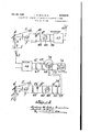
- FIG. 1 shows schematically pendulums with circuit arrangements for each pendulum for selecting a high frequency for each circuit and comparing the frequencies, the pendulum circuits being disposed either at the same station or at stations adequately close to each other to permit of the pendulum circuits beingcbiinected by electrically conducting wires or the like.
- Fig. 2 shows schematically an arrangement in which radio communication is effected between the pendulum circuits.
- reference numeral l designates a pendulum which is mounted for oscillatory movement with.
- a mirror 3 is dis sed upon the top of the pendulum l for oscillatory movementwith the pendulum.
- a mirror 4 is dis-' posed infixed position above the pendulum to re- 59" fleet light from a lamp 5 to the mirror 3, which electric cell 7.
- the photo-electric cell ll generates a pulsation of electric current each time the pendulum passes through equilibrium position.
- the wave representing the oscillations of the pendulum. is substantially sinusoidal. Since, however, an impulse is imparted to the photoelectric cell only atv the times when the pendulum passes its equilibrium position, the characteristics of the current set up by the photoelectric cell will be sharply peaked and will; therefore, contain a number of harmonics of the frequency of the oscillations of the pendulum but will have a fundamental frequency the same as the frequency of the pendulum.
- the distorted pulsations of electric energy are amplified and are caused to actuate mechanical means for successively selecting a higher harmonic through the following arrangement of parts.
- Resistance 8 and a battery 9 are provided inthe circuit of the photo-electric cell in the usual manner.
- the photo-electric current is amplified by the amplifier i0 and fed to the transformer ii, the secondary of which is connected in series with the battery i2 and across the gridof a vacuum tube Iii.
- a condenser M connected acims the plate battery i5 and a resistance it in series; this combination of elements is connected in series with an iron core coil ii which drives a reed M.
- the natural frequency of the reed is chosen from five to ten times as high as-the frequency of the pendulum l.
- the reed vibrates with respect to its supporting base as shown. If the natural frequency of the reed is, for example, five times the frequency of the pendulum i, it is seen that the reed will respond only to thefifth harmonic of the pendulum i.
- Electrical impulses transmitted flOl: the reed l8 are caused to actuate further mechanical means for selecting a still higher harmonic for the system through the following arrangement of parts.
- a condenser is formed bymeans or a plate I9 and the flat top of the reed i 8.
- a variable condenser 20 and a coilv 2i are connected in parallel across the condenser is and across the grid of a, tube 22.
- a variable feedback condenser 23 is connected from the grid to'the plate of the tube 22.
- a condenser 24 and a coil 25 in series. are connected across the plate and filament of the tube 22 as is also a variable condenser 26 and a g radio frequency choke 21, 3 battery 28 and the primary of a transformer 23 in series.
- the secondary of thetransformer 23 and a battery 33 are connected across the grid and filament of a vacuum tube 3
- a condenser 33 is connected across the battery 32 and resistance 34.
- the coil 35 drives a tuning fork 33.
- the irequency of the tuning fork'33 is from five to ten ,times as high as the frequency of the reed l8.
- tuning fork 33 will, therefore, respond to that Electrical means having its input connected to I the output of the tuning fork circuit is provided for further successively selecting a higher harmonic for each system.
- This electrical means comprises a magnetized iron cored coil 31 which cooperates with the tuning fork to pick up elecv trical impulses due to the vibrations of the tuning fork. These electric impulses are fed across the grid and filament of a vacuum tube 38.
- are connected in parallel across the plate andfilament of the vacuum tube 38; The inductance of the choke coil grids of a multiple grid tube 53.
- a condenser ,42 connects this resonant system to a resistance 43 which is connected across the grid and filament of a vacuum tube 44.
- a coil 45, variable condenser 43, condenser 41, and resistance 48 in the same way as in the circuit between the vacuum tubes 38 and 44.
- the inductance of the coil 45 and the capacity of the variable condenser 43 are, however, so chosen that the resonant :frequency of this system will be five to ten times the resonant frequencyof the system composed of the coil 43 and the variable condenser 4
- a B battery 39 provides the necessary voltage for the vacuum tubes 33, 44, and 43.
- any desired number of additional circuits such as those shown between the vacuum tubes 38 and 44 and between the vacuum.
- tubes 44 and 43 are inserted following the tube 49, each circuit having'a resonant system analogous to, the resonant system composed, of coil 43 and variable condenser 4
- a resonant system analogous to, the resonant system composed, of coil 43 and variable condenser 4
- resistance 53 is connected inthe plate circuit of the vacuum tube 43'.
- is connected in series with the resistance 50 across one of the 53 and a C-battery 54 are provided in the circuit.
- the system above described comprising elements .I to 54 is duplicated by another system identical in all' respects with the system above. described and constituting elements I' to 54'. --'I'heselected high harmonic of the system to 54 is compared with the selected .high harmonic of the system to 54' through the following arrangement of parts.
- the system to 54' is connected to anothergrid of the multiple grid tube 53.
- a battery 51 and an oscillograph 58 are connected in the plate circuit of the multiple grid tube 53.
- the multiple grid tube 53 is fed by the two radio frequencies of one or several million cycles of the systems I to 54 and to 54 so that the beat frequency is recorded by the oscillograph.
- the oscillograph will record a frequency of one cycle per second.
- the construction shown permits 7 of' increasing the amplitude of any harmonic desired, for example the millionth harmonic, of the pendulums and respectively and of recording on the oscillograph 53 the difference between these harmonics.
- dulums it can be used in the comparison of the frequencies of vibrating systems, such as tuning forks, clocks, 0sci1lators,,0r the like. If, for example, it is desired to adjust the frequency of a tuningfork so that it will be the same as the frequency of another tuning fork toone part in one million, it is only necessary to observe the beat frequency of the two systems for a few seconds. after making each adjustment. If the millionth harmonic is employed, the tuning fork frequencies will agree to within one part in one million when the beat frequency is one cycle per second.
- the pendulum I may be located at a base station while the pendulum I may occupy successively so-called field stations which may be at a distance of several hundred'miles from the base station, In such a case, the condenser -5.
- the resistance constitutes the output resistance of its system which leads into a radio transmitter 32 and an antenna 3
- the system at the field station is provided with a receiving antenna 33 which leads into a radio receiver '34.: A resistanceis connected .ln the output from the radio receiver '34.
- a condenser 31 is connected inseries with theresistance' 35 across one of the grids of a multiple'grid tube 12.
- a grid resistance 33 and a C-battery 33 are provided in the circuit.
- the system to 54' is connected to another grid of the multiple grid tube 12.
- a battery I3 and an oscillograph 14 are connected in the plate circuit of the multiple grid tube l2.
- the resistance 351s equal to the resistance 53'.
- the radio frequency of the system I to 53 is transmitted by means of the wireless transmitter 32 and antenna 3
- radio frequency is received bythe antenna 33 and the wireless receiver 34 and combined with thelocally produced radio frequency in the multiple grid tube I2.
- the beat frequency is recorded by the oscillograph 14.
- the radio frequency of thesystemto 54' may be transmitted by wireless to the base station and combined at the base station with the radio frequency of the system to 53 in the multiple grid mentioned train of electric impulses and means for observing the frequency of the harmonics as tube and the beat frequency recorded at the base station by the oscillograph.
- the length of time necessary for observing differences in gravity by means of pendulums can be reduced to a few seconds.
- an oscillating pendulum means for setting up by the motion of said pendulum a corresponding train of electrical impulses, the fundamental 'frequency of which is the same 'as that of the pendulum, means for setting up mechanical vibrations by a harmonic of said train of electrical impulses, means for setting up by said mechanical vibrations a corresponding train of electrical impulses the fundamental frequency of which is the same as that of said mechanical vibrations, means for obtaining a harmonic of said second the fundamental frequency changes.
- a system for measuring changes in gravity along the earth's surface comprising an instrumentality capable of indicating the force of gravity by oscillations, an electrical circuit, means for impressing thereon a current containing harmonics of said oscillations, a. second oscillating means, the frequency of oscillation of which varies with the amplitude of its oscillations, associated with said current in a manner to be oscillated by one of said harmonics, a secondelectrical circuit, means for impressing thereon a current of the oscillations of said second oscillating means and means for multiplying the frequency of one of said harmonics to a predetermined value.
- a system for measuring changes in gravity along the earth's surface comprising an instrumentality capable of indicating the force of grav- .ity by oscillations, an electrical circuit, means mechanically independent of said instrumentality for impressing on said circuit a current containing harmonics ofsaid oscillations, at second oscillating means, the frequency of oscillation of which varies with the amplitude of its oscillations, associated with said circuit in a manner to be oscillated by one of said harmonics, a second electrical circuit, means for impressing thereon a current containing harmonics of the oscillations of said second oscillating means and means for multiplying the frequency of said current to a predetermined value.
- a system for measuring changes of gravity along the earth's surface comprising an instrumentalitycapable of indicating the force of gravity by oscillations and having a given natural frequency, an electrical circuit, means for impressing thereon a current containing harmonics of said oscillations, a second oscillating means,-
- the frequency of oscillation of which varies with the amplitude of its oscillations having a natural frequency which is a multiple of the natural frequency of said instrumentality associated with such circuit in a manner to be oscillated by one of said harmonics, a second electrical circuit, means for impressing thereon a current containing harmonics of the oscillations of said second oscillating means and means for multiplying the frequency of said current to a predetermined value.
Landscapes
- Physics & Mathematics (AREA)
- General Physics & Mathematics (AREA)
- Life Sciences & Earth Sciences (AREA)
- General Life Sciences & Earth Sciences (AREA)
- Geophysics (AREA)
- Measurement Of Mechanical Vibrations Or Ultrasonic Waves (AREA)
Description
Feb. 28, 1939. w. BLAU ET'AL APPARATUS FOR commune A PLURALITY 0F oscnmuomr SYSTEMS I 2 Sheets-Sheet 1 Filed Nov. 8, 1934 4 1 1/ 1 J v HII'ILJS v V v v v i k P56646441 T 01F; 19 Maura/we r TON/566% x i 50 FRap-mewc r- I 51M? i 1 T M I I a.
Fb. 28, 1939. L. w. BLAU ET AL 2,148,678
APPARATUS FOR COMPARING A PLURALITY- 0F OSCILLATORY SYSTEMS Filed Nov. 8, 1934 2 Sheets-Sheet 2 61 {647 WWI? Eras/1459 Patented Feb. 1939 APPARATUS FOR COMPARING A PLURAHTY F OSCILLATORY SYSTEMS Ludwig W. Blau and Andrew B. Bryan, Houston,
Tex, assignorsrto Standard Oil Development Company, a. corporation-oi. Delaware Application November 8, 1934, Serial No. 752,064
6 Claims.
This invention relates to improvements in apparatus for comparing a plurality of oscillatory systems.
"It is an object of this invention to reduce the time of observation of gravity measurements when using pendulums or other oscillatory systems to a few seconds per station while retaining the required accuracy of one partin ten million. This object is accomplished by successively selecting and amplifying harmonics of the pendulum frequency up to a frequency of several million cycles per second. The two radio frequencies thus obtained from the two pendulums at two different locations are then combined to yield a beat frequency which is recorded by an oscillograph. If two identical pendulums are employed, they will have the same period if located'at the same place.
It is seen, then, that if one of these pendulums is moved to a point at which the value of gravity is greater by one part in one millon parts, and if the one-millionth harmonic is being used in both cases, there will be a beat frequency of one-half cycle per second which is recorded by the oscillog'raph. It is thus necessary to observe and record for a few seconds only as compared with observation periods of'several minutes to six hours customaryby other methods previously known and' employed. The invention will be fully understood from the following description taken in connection with the accompanying drawings in which latter- Fig. 1 shows schematically pendulums with circuit arrangements for each pendulum for selecting a high frequency for each circuit and comparing the frequencies, the pendulum circuits being disposed either at the same station or at stations suficiently close to each other to permit of the pendulum circuits beingcbiinected by electrically conducting wires or the like.
Fig. 2 shows schematically an arrangement in which radio communication is effected between the pendulum circuits.
Referring particularly to Fig. 1 of the draw- I ings, reference numeral l designates a pendulum which is mounted for oscillatory movement with.
respect to the ,knife edge 2; a mirror 3 is dis sed upon the top of the pendulum l for oscillatory movementwith the pendulum. A mirror 4 is dis-' posed infixed position above the pendulum to re- 59" fleet light from a lamp 5 to the mirror 3, which electric cell 7. The photo-electric cell ll generates a pulsation of electric current each time the pendulum passes through equilibrium position.
It is to be noted here that while the oscillations of the pendulum will be sinusoidal, or nearly so, and, therefore, practically free of harmonics, the photo-electric cell distorts the oscillations markedly, thus introducing harmonics.
The wave representing the oscillations of the pendulum. is substantially sinusoidal. Since, however, an impulse is imparted to the photoelectric cell only atv the times when the pendulum passes its equilibrium position, the characteristics of the current set up by the photoelectric cell will be sharply peaked and will; therefore, contain a number of harmonics of the frequency of the oscillations of the pendulum but will have a fundamental frequency the same as the frequency of the pendulum.
The distorted pulsations of electric energy are amplified and are caused to actuate mechanical means for successively selecting a higher harmonic through the following arrangement of parts. Resistance 8 and a battery 9 are provided inthe circuit of the photo-electric cell in the usual manner. The photo-electric current is amplified by the amplifier i0 and fed to the transformer ii, the secondary of which is connected in series with the battery i2 and across the gridof a vacuum tube Iii. In the plate circuit of the vacuum tube l3, there is disposed a condenser M connected acims the plate battery i5 and a resistance it in series; this combination of elements is connected in series with an iron core coil ii which drives a reed M. The natural frequency of the reed is chosen from five to ten times as high as-the frequency of the pendulum l. The reedvibrates with respect to its supporting base as shown. If the natural frequency of the reed is, for example, five times the frequency of the pendulum i, it is seen that the reed will respond only to thefifth harmonic of the pendulum i. Electrical impulses transmitted flOl: the reed l8 are caused to actuate further mechanical means for selecting a still higher harmonic for the system through the following arrangement of parts. A condenser is formed bymeans or a plate I9 and the flat top of the reed i 8. A variable condenser 20 and a coilv 2i are connected in parallel across the condenser is and across the grid of a, tube 22. A variable feedback condenser 23 is connected from the grid to'the plate of the tube 22. A condenser 24 and a coil 25 in series. are connected across the plate and filament of the tube 22 as is also a variable condenser 26 and a g radio frequency choke 21, 3 battery 28 and the primary of a transformer 23 in series. The secondary of thetransformer 23 and a battery 33 are connected across the grid and filament of a vacuum tube 3|, in the plate circuit of which are connected a B battery 32, resistance 34, and
a. driving coil 35 in series. A condenser 33 is connected across the battery 32 and resistance 34.
The coil 35 drives a tuning fork 33. The irequency of the tuning fork'33 is from five to ten ,times as high as the frequency of the reed l8. The
' Any desired number of additional circuits such as those shown between the vacuum tubes 38 and 44 and between the vacuum. tubes 44 and 43 are inserted following the tube 49, each circuit having'a resonant system analogous to, the resonant system composed, of coil 43 and variable condenser 4| or the coil 45 and the variable condenser 43, the natural frequency of which system is so chosen as to resonate at a frequency from five to ten times the frequency of the precedin resonant system until the frequency has been increased to the desired frequency, which may be from one to several million cycles per second. A
The multiple grid tube 53 is fed by the two radio frequencies of one or several million cycles of the systems I to 54 and to 54 so that the beat frequency is recorded by the oscillograph.
Thus, if the frequency of the system to 54 is one million cycles and the frequency of the system I to 54 is one million and one cycles, the oscillograph will record a frequency of one cycle per second.
The construction shown permits 7 of' increasing the amplitude of any harmonic desired, for example the millionth harmonic, of the pendulums and respectively and of recording on the oscillograph 53 the difference between these harmonics.
dulums, it can be used in the comparison of the frequencies of vibrating systems, such as tuning forks, clocks, 0sci1lators,,0r the like. If, for example, it is desired to adjust the frequency of a tuningfork so that it will be the same as the frequency of another tuning fork toone part in one million, it is only necessary to observe the beat frequency of the two systems for a few seconds. after making each adjustment. If the millionth harmonic is employed, the tuning fork frequencies will agree to within one part in one million when the beat frequency is one cycle per second.
In the use of the-device in comparing accelera tions due to gravity at spaced points on the crust ofthe earth, the pendulum I may be located at a base station while the pendulum I may occupy successively so-called field stations which may be at a distance of several hundred'miles from the base station, In such a case, the condenser -5.| is omitted from the system at the base station;
The resistance constitutes the output resistance of its system which leads into a radio transmitter 32 and an antenna 3| as shown in Fig. 2. The system at the field stationis provided with a receiving antenna 33 which leads into a radio receiver '34.: A resistanceis connected .ln the output from the radio receiver '34. A condenser 31 is connected inseries with theresistance' 35 across one of the grids of a multiple'grid tube 12. A grid resistance 33 and a C-battery 33 are provided in the circuit. The system to 54' is connected to another grid of the multiple grid tube 12. A battery I3 and an oscillograph 14 are connected in the plate circuit of the multiple grid tube l2. The resistance 351s equal to the resistance 53'. The radio frequency of the system I to 53 is transmitted by means of the wireless transmitter 32 and antenna 3| to the field station,
where the radio frequency is received bythe antenna 33 and the wireless receiver 34 and combined with thelocally produced radio frequency in the multiple grid tube I2. The beat frequency is recorded by the oscillograph 14. Conversely,
the radio frequency of thesystemto 54' may be transmitted by wireless to the base station and combined at the base station with the radio frequency of the system to 53 in the multiple grid mentioned train of electric impulses and means for observing the frequency of the harmonics as tube and the beat frequency recorded at the base station by the oscillograph.
By the construction described, the length of time necessary for observing differences in gravity by means of pendulums can be reduced to a few seconds.
Various changes may be made within the scope of the appended claims in which it is desired to claim all novelty inherent in the invention as broadly as the prior art permits.
We claim:
1. In a system for observing gravitational forces, an oscillating pendulum, means for setting up by the motion of said pendulum a corresponding train of electrical impulses, the fundamental 'frequency of which is the same 'as that of the pendulum, means for setting up mechanical vibrations by a harmonic of said train of electrical impulses, means for setting up by said mechanical vibrations a corresponding train of electrical impulses the fundamental frequency of which is the same as that of said mechanical vibrations, means for obtaining a harmonic of said second the fundamental frequency changes.
2. A system for measuring changes in gravity along the earth's surface, comprising an instrumentality capable of indicating the force of gravity by oscillations, an electrical circuit, means for impressing thereon a current containing harmonics of said oscillations, a. second oscillating means, the frequency of oscillation of which varies with the amplitude of its oscillations, associated with said current in a manner to be oscillated by one of said harmonics, a secondelectrical circuit, means for impressing thereon a current of the oscillations of said second oscillating means and means for multiplying the frequency of one of said harmonics to a predetermined value.
3. A system for measuring changes in gravity along the earth's surface, comprising an instrumentality capable of indicating the force of grav- .ity by oscillations, an electrical circuit, means mechanically independent of said instrumentality for impressing on said circuit a current containing harmonics ofsaid oscillations, at second oscillating means, the frequency of oscillation of which varies with the amplitude of its oscillations, associated with said circuit in a manner to be oscillated by one of said harmonics, a second electrical circuit, means for impressing thereon a current containing harmonics of the oscillations of said second oscillating means and means for multiplying the frequency of said current to a predetermined value.
4. A system for measuring changes of gravity along the earth's surface, comprising an instrumentalitycapable of indicating the force of gravity by oscillations and having a given natural frequency, an electrical circuit, means for impressing thereon a current containing harmonics of said oscillations, a second oscillating means,-
the frequency of oscillation of which varies with the amplitude of its oscillations, having a natural frequency which is a multiple of the natural frequency of said instrumentality associated with such circuit in a manner to be oscillated by one of said harmonics, a second electrical circuit, means for impressing thereon a current containing harmonics of the oscillations of said second oscillating means and means for multiplying the frequency of said current to a predetermined value.
' 80 5. A system, according to claim 2, in which
Priority Applications (1)
| Application Number | Priority Date | Filing Date | Title |
|---|---|---|---|
| US752064A US2148678A (en) | 1934-11-08 | 1934-11-08 | Apparatus for comparing a plurality of oscillatory systems |
Applications Claiming Priority (1)
| Application Number | Priority Date | Filing Date | Title |
|---|---|---|---|
| US752064A US2148678A (en) | 1934-11-08 | 1934-11-08 | Apparatus for comparing a plurality of oscillatory systems |
Publications (1)
| Publication Number | Publication Date |
|---|---|
| US2148678A true US2148678A (en) | 1939-02-28 |
Family
ID=25024701
Family Applications (1)
| Application Number | Title | Priority Date | Filing Date |
|---|---|---|---|
| US752064A Expired - Lifetime US2148678A (en) | 1934-11-08 | 1934-11-08 | Apparatus for comparing a plurality of oscillatory systems |
Country Status (1)
| Country | Link |
|---|---|
| US (1) | US2148678A (en) |
Cited By (2)
| Publication number | Priority date | Publication date | Assignee | Title |
|---|---|---|---|---|
| US2437929A (en) * | 1941-06-18 | 1948-03-16 | Hamilton Watch Co | Timing apparatus |
| US2595092A (en) * | 1947-05-19 | 1952-04-29 | Standard Oil Dev Co | Method and apparatus for underwater gravity surveying |
-
1934
- 1934-11-08 US US752064A patent/US2148678A/en not_active Expired - Lifetime
Cited By (2)
| Publication number | Priority date | Publication date | Assignee | Title |
|---|---|---|---|---|
| US2437929A (en) * | 1941-06-18 | 1948-03-16 | Hamilton Watch Co | Timing apparatus |
| US2595092A (en) * | 1947-05-19 | 1952-04-29 | Standard Oil Dev Co | Method and apparatus for underwater gravity surveying |
Similar Documents
| Publication | Publication Date | Title |
|---|---|---|
| US1995305A (en) | Method and apparatus for determining the force of gravity | |
| US2268587A (en) | Distance determining system | |
| US2322681A (en) | Condenser gravity meter | |
| US2309560A (en) | Method and apparatus for measuring and recording vibrational effects | |
| US1543124A (en) | Frequency standard | |
| US1975516A (en) | Gravity indicator | |
| US3631756A (en) | Apparatus and method for tuning musical instruments | |
| US2148678A (en) | Apparatus for comparing a plurality of oscillatory systems | |
| US1560056A (en) | Source of waves of constant frequency | |
| US1849870A (en) | Telemetric system | |
| US2646469A (en) | Balanced multichannel amplifier for wide amplitude range | |
| US2149756A (en) | Measuring apparatus | |
| US2015410A (en) | Vibrating system | |
| US2602838A (en) | Electrical measuring instrument | |
| US2020039A (en) | Horologe system | |
| Dye | VII. A self-contained standard harmonic wave-meter | |
| US1951226A (en) | Measurement of gravitational forces | |
| US2257285A (en) | Apparatus and method for tuning | |
| US2446428A (en) | Apparatus for producing indications of movement of an element | |
| US2049724A (en) | Method of geological exploration | |
| US2272066A (en) | Ultra short wave system | |
| US1864543A (en) | Frequency measuring circuits | |
| US1708945A (en) | Selective transmission system | |
| US1897204A (en) | Means for the remote reading of instruments | |
| US2291779A (en) | Geophysical apparatus and method |