US2144192A - Winding machine - Google Patents
Winding machine Download PDFInfo
- Publication number
- US2144192A US2144192A US107098A US10709836A US2144192A US 2144192 A US2144192 A US 2144192A US 107098 A US107098 A US 107098A US 10709836 A US10709836 A US 10709836A US 2144192 A US2144192 A US 2144192A
- Authority
- US
- United States
- Prior art keywords
- package
- roll
- yarn
- drive
- lever
- Prior art date
- Legal status (The legal status is an assumption and is not a legal conclusion. Google has not performed a legal analysis and makes no representation as to the accuracy of the status listed.)
- Expired - Lifetime
Links
Images
Classifications
-
- B—PERFORMING OPERATIONS; TRANSPORTING
- B65—CONVEYING; PACKING; STORING; HANDLING THIN OR FILAMENTARY MATERIAL
- B65H—HANDLING THIN OR FILAMENTARY MATERIAL, e.g. SHEETS, WEBS, CABLES
- B65H63/00—Warning or safety devices, e.g. automatic fault detectors, stop-motions ; Quality control of the package
- B65H63/02—Warning or safety devices, e.g. automatic fault detectors, stop-motions ; Quality control of the package responsive to reduction in material tension, failure of supply, or breakage, of material
- B65H63/024—Warning or safety devices, e.g. automatic fault detectors, stop-motions ; Quality control of the package responsive to reduction in material tension, failure of supply, or breakage, of material responsive to breakage of materials
- B65H63/036—Warning or safety devices, e.g. automatic fault detectors, stop-motions ; Quality control of the package responsive to reduction in material tension, failure of supply, or breakage, of material responsive to breakage of materials characterised by the combination of the detecting or sensing elements with other devices, e.g. stopping devices for material advancing or winding mechanism
- B65H63/0364—Warning or safety devices, e.g. automatic fault detectors, stop-motions ; Quality control of the package responsive to reduction in material tension, failure of supply, or breakage, of material responsive to breakage of materials characterised by the combination of the detecting or sensing elements with other devices, e.g. stopping devices for material advancing or winding mechanism by lifting or raising the package away from the driving roller
-
- B—PERFORMING OPERATIONS; TRANSPORTING
- B65—CONVEYING; PACKING; STORING; HANDLING THIN OR FILAMENTARY MATERIAL
- B65H—HANDLING THIN OR FILAMENTARY MATERIAL, e.g. SHEETS, WEBS, CABLES
- B65H2701/00—Handled material; Storage means
- B65H2701/30—Handled filamentary material
- B65H2701/31—Textiles threads or artificial strands of filaments
Definitions
- This invention relates to improvements in winding machines for winding cops, cones, coils and other forms of packages of yarn, thread and other strand materials.
- package is used in a general sense to indicate any form of product wound on the machine, and the term yarn is employed to designate broadly all kinds of materials, whether textile or otherwise.
- One object of the invention is to provide a winding machine having improved stopping mechanism which is entirely automatic and positive in arresting the winding operation when the strand breaks or its supply is exhausted.
- Another object of the invention is to provide in a machine of the type indicated stopping mechanism which is controlled and set in action by means normally held inoperative by the yarn being Wound; and means for automatically returning the controlling means to initial position immediately following each arrestment of the winding operation whereby to facilitate the piecing-up or tying-in operation.
- Another object of the invention is to provide a machine of the type indicated having its stopping mechanism entirely enclosed or housed to prevent accumulation of dust and lint thereonliable to impede its normally rapid action or cause wear on the parts.
- Another object of the invention is to provide in a machine of the type indicated improved starting means for gradually lowering the yarnreceiver or package into contact with the driving means to avoid a sudden draft on the yarn liable to strain or break the strand.
- Another object of the invention is to provide a machine of the type indicated having means incorporated therein for preventing jumping or vibration of the package on the drive-roll or drum during the winding operation whereby to maintain the pressure of the package against the drum substantially constant and produce a more uniformly wound and stable package, while at the same time guardingagainst damage to the fibers tion of the parts of the stopping mechanism during normal operation of the machine;
- Fig. 3 is a view similar to Fig. 2 showing another position of the parts of the stopping mechanism during the winding operation;
- Fig. 4 is a similar view illustrating the manner in which the stopping mechanism acts to arrest the winding operation when the yarn breaks or its supply is exhausted;
- Fig. 5 is a detailed view of a portion of the stopping mechanism illustrating the manner in which the drop-wire or control-lever is automatically reset immediately following the arrestment of the winding operation;
- Fig. .6 is a sectional view on line 6'6 of Fig. 2'; 5
- Fig. 7 is a sectional viewon line 1--'
- Fig. .8 isasectional plan view on line 88 of Fig. 7;
- Figs. 9, 10, 11 and 12 are sectional views taken on lines 9.9, ins-Ill, ll-ll and l2-l2, respectively, ofFig. 2.
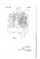
- the winding machine herein illustrated is of .the double gang type comprising a plurality of winding units arranged in opposite series along the sides of a horizontal frame or bed 2 supported by suitable legs 3. Spaced along the top of the bed. 2 are a series of brackets or standards 1 which supportcbearings for the driving shaft and other parts of the winding mechanism, two opposite units being located between each pair of brackets but only one unit being herein shown.
- each frame member .”I is constituted by a hollow boxlike central portion .8 bolted to the bed 2 and having an open top.
- a depending arcuate well or reservoir 9 for containing a supply of lubricant indicated at O in the drawings.
- the member .1 . is provided with an overhanging housing .IEI which communicates with the interior of the central portion 8 while being ofiset with respect thereto.
- the housing [0 forms a chamber in which the parts of the stopping mechanism are mounted in the manner as later explained.
- the open top of the member! is closed by an arched cover ll secured in place by screws l2, see Fig.
- the framemember 1 and .covers H and 13 are'preferably constructed as die-castings to render themstrong n d able. y t l ht in e ght an t efie b economies in manufacture by eliminating costly finishing operations.
- the winding mechanism comprises only two principal elements, namely: the winding mandrel orspindle
- the drive-roll 20 for rotating the yam-receiver and in which is embodied the means for traversing the yarn back and forth axially of the package being wound.
- the drive-roll 20 for rotating the yam-receiver and in which is embodied the means for traversing the yarn back and forth axially of the package being wound.
- the drive-roll 20 is carried on and rotated by a horizontal shaft 23 journaled in ball-bearings 24 supported by the brackets 1 and held in place by bearing caps 25; it being noted that the shaft 23 is extended throughout the whole length of the gang machine and may carry the driverolls. for any desired number of winding units.
- the present machine is shown as adapted for winding packages of conical form in which the yarn body is built up on any suitable support or receiver, a fiber cop-tube 0 being illustrated in Fig.1 as mounted on a cop-holder l8 rotatable on the winding-spindle l5.
- the winding-spindle I5 is swiveled to they forked end of an arm 26 which is carried by a rockable member or support 40 pivoted on a sleeve or bushing 21 enclosing a shaft 35 extending through the frame-members 1.
- the sleeve 21 passes through openings in the opposite covers II and hollow frame-members I of one pair in the series and is provided with end-flanges 30 which abut the inner faces of the walls thereof to-hold it from axial displacement.
- the sleeve 21 is held from rotation in the frame-members 1 by means of set-screws 3
- a sleeve 21 is positloned between each pair of frame-members 1 and in addition to serving as bushings for the several spindle-arms they provide elongated bearings for the shaft 35 which rotates therein.
- the shaft 35 extends longitudinally throughout the entire length of the machine and carries a plurality of eccentric disks 36 positioned within the housings 8, one disk being provided for each pair of opposite winding units.
- the disks 36 are keyed at 31 to the shaft 35 and held axially in place by set-screws 38.
- Oil 0 is drawn upwardly from the reservoir 9 to lubricate the interior of the sleeves 21 by means of oil-rings 39 suspended on the shaft 35 and depending into the oil supply.
- the rockable member or support 40 previously described as carrying the spindle-arm 26, is formed with spaced bearings 4
- serves to hold the arm in place while constituting one element of a builder motion, not herein shown in detail.
- the hubportionof the support 40 may be split diametrically or constructed in two halves 42 and 43 having abutting projections or arms 44 at one side bound together by means to be later described.
- the two parts 42 and 43 of the hub are separated by a slit, being clamped together by a binder-screw 45 having its shank passing through a hole in the part 43 and screwed into a threaded hole in the opposite part 42.
- the hub-portion of the member 40 is thus caused to frictionally grip the sleeve 21 to resist its turning movement thereon to control the swinging movement of the spindle-arm 26 in the manner and for the purpose as later explained.
- the supporting member 40 may be held in place against the side of the frame-member 1 by means of a collar 52 fixedly secured to the sleeve 21 and constituting a second element of the builder motion.
- the present invention makes use of a dash-pot indicated at 59 in Figs. 3, 4 and '7.
- Spaced plates 41 fastened to the arms 44 of the spindle-arm support 40 form.
- Engaging the socket 48 and slidable thereon is a rectangular block 55 pivotally carried by a pin 56 at the upper end of an elbowshaped connecting link or bar 51.
- the link 51 is arranged for vertical sliding movement in a guideway 58 formed on the inner face of the cover l3. see Figs. 7 and 8.
- a cylindrical piston or plunger 62 Attached to the lower horizontally-extending portion of the link 51 is a cylindrical piston or plunger 62.
- the plunger 62 is slidable in a well or cylinder 64 formed in the bottom or floor of the frame-member 1 and is flattened along one side to provide a restricted vent 65 from the cylinder 64 to permit oil 0 to escape from and flow into the cylinder as the plunger 62 is raised and lowered therein.
- the spindle-arm 26 is lowered resistance is offered to this movement due to the restricted opening or vent 65 and, as a result, the package or coptube, as the case may be, is brought slowly into contact with the rotating drive-roll 20 to provide for starting the rotation of the package slowly so as not to strain or break the yarn.
- the spindle-arm 26 When the winding machine is inoperative the spindle-arm 26 is held in raised position by the engagement of the end of a horizontally extending latch or detent-bar 10 in a notch 1
- the detentbar 10 is slidable in spaced bearings 12 on the inner face of the cover l3, see Fig, 9, and is urged into engagement with the notch 1
- the bar 10 is adapted to be withdrawn from engagement with the slot 1
- the lever 18 is fastened by a set screw 82 to a transverse shaft 19 pivotally mounted in bearings and 8
- the shaft 19 is constituted as the bent end of a starting handle 85 which reaches upwardly and forwardly and has a knob or other hand-rest 86 at its end adapted to be conveniently grasped by the operator of the machine.
- the handle 85 When the handle 85 is depressed the starting lever 18 is rocked in a clockwise direction, as viewed in Fig. 4, and through the engagement of its upper offset end with an abutment 83 on the detent-bar 10 the latter is slid forwardly to release it from engagement with the slot 1
- the handle 85 is normally held in raised position by a coil-spring 80 having one end hooked through a hole in the lever 18 and its .other end anchored to a pin 09 on the housing I0.
- An arm 90 integral with the starting lever 18 engages the bottom wall of the housing I to limit the movement of the lever and thereby that of the handle 85.
- a stop is provided for limiting the downward movement of the spindle-arm 26 to prevent the cop-holder I8 from contacting with the driveroll 20 to score or otherwise damage the surface of the latter when the cop-tube C is removed from the spindle.
- the stop comprises a set-screw 9i screwed into a boss 92 on the side of the cover I3 with its head adapted to engage the under side of the lower projection 44 on the hub 40 of the spindle-arm 26.
- may be adjusted vertically in the boss 92 and locked in adjusted position by a check-nut 03.
- the stopping mechanism which operates to raise the spindle I away from the drive-roll 20 to arrest the winding when the yarn breaks or its supply is exhausted comprises an intermittently operated mechanism constructed and arranged as next described.
- the sides of the housing or chamber I0 are provided with alining holes 95 for receiving circular bosses 90 on the inner walls of the opposite covers i3.
- Mounted for pivotal movement in axial holes in the bosses 90 is a transverse shaft or pivotrod 91.
- a walking beam or oscillator I00 has its hub IOI pivoted on the shaft 9'1 and is formed with opposite arms I02 radiating from the hub.
- the oscillator I05 is bifurcated as shown in Figs. 3 and 4 with the sides I03 of the bifurcation arranged to straddle the periphery of the eccentric or cam v3E5 to cause the oscillator to be continuously rocked therefrom during the rotation of the eccentric.
- the oscillator I00 acts to operate the stopping mechanism of two opposite winding units by means of its opposite arms I02, but it will be sufficient to describe the mechanism of one unit only.
- Pivoted on a stud I05 in the end of the arm I02 is a bell-crank lever I06, see Figs. 3, 4 and 5, one arm 50! of which is provided with a slot I08 in its side.
- Engaged in the slot I 08 is a rectangular block I00, see Fig. 7, pivotally mounted on a pin H0 projecting from the side of the vertical link 51.
- the other arm II2 of the bell-crank lever I06 carries a stud H3, see Fig. 11, to which is pivotally connected one end of a horizontal bar H5.
- the detent-means for restraining the bar H5 from forward movement comprises a pawl I20 having a toe .I2.I for engaging the shoulder II! on the bar.
- the pawl I20 is fast on the inner end of a pivot-rod I22 extending through a bearing boss I23 on the housing cover I3.
- a pair of plates or washers I24 At the outer threaded end of the rod I22 is a pair of plates or washers I24, between which is held the hooked end of an elbow-shaped breakage-lever or drop-wire I25.
- Nuts I26 screwed onto the rod I22 and set up against the plates I24 bind the lever I25 fixedly to the rod.
- the breakage-lever I25 extends forwardly and downwardly and terminates in a right-angular bent portion or crossbar I21 which. lies parallel to the axis of the drive-roll 20.
- the yarn, indicated at 11, passes over the end portion E2! of the lever I25 and tends to depress the latter to normally maintain the toe I2I of the pawl I20 raised out of the path of movement of the bar H5.
- the crossbar I 2'! rests against a shelf or ledge I29 formed at the upper end of a tension bracket I30, see Figs. 2, 3 and 4, which is mounted on a rail I34 extending along the side of the machine; the rail I34 being supported from the legs 3 by spaced brackets I35.
- the yarn y draws upwardly from a supply-bobbin B, held on a spindle I3!
- a stud I45 screwed into a boss I41 on the interior of the housing I0 as shown in Fig. 9.
- the upper end of the vertical arm I48 of the lever I45 extends laterally into position to be engaged by an abutment I50 on the side of the detent-bar I0 for a purpose as later explained.
- the forwardly-extending arm I50 of the lever M5 is offset downwardly and its end rounded to adapt it to engage against the under side of the pawl I20.
- the opposite or rearward arm I5I .of the lever I45 is provided with a suitable weight I52 which tends to swing the lever in a counterclockwise direction as viewed in Fig.
- a suitable paper or fiber cop-tube or other yarnreceiver C is placed on the spindle I5 while the latter is in raised position as shown in Fig. 4.
- the yarn y is next drawn upwardly from the supply-bobbin B, passed through the tensiondevice I40 and slub-catcher MI, and threaded beneath the guide-wire I42. From the guidewire I42 the yarn is led across the crossbar I2'I of the breakage-lever or drop-wire I25 which rests upon the shelf I29, passed across the driveor traverse-roll 20 and its end attached to the cop-tube C.
- the unit is then ready to start the operation of winding a package.
- the two shafts 23 and 35 are constantly rotated by suitable driving means, not herein shown, and the oscillator I00 is continuously rocked by the eccentric disk 36 on the shaft 35.
- the bell-crank lever I06 is thus caused to be raised and lowered bodily and due to its engagement with the block I09 it is rocked to reciprocate the bar II5.
- the pawl I20 is held inoperative by the forward end of the weighted lever I45 the bar simply rides back and forth over the roller II6 without hindrance.
- the starting handle 85 is depressed, thereby rocking the lever I8 to shift the detent-bar I9 forwardly to disengage its inner end from the notch II in the vertical connecting link 51.
- the spindle-arm 26 is thus released to cause it to descend to lower the cop-tube C into surface contact with the periphery of the roll 20.
- the arm 26 is lowered gradually, due to the resistance offered by the dash-pot 50, and the tube C is brought gently into contact with the roll 20. Through this provision the winding is started slowly without causing undue strain on the yarn.
- the frictional grip of the split hub of the spindle-arm support 40 on the sleeve 21 compensates for any slack or looseness that may occur between the elements and thus assists in effecting the gradual lowering of the spindle without chattering or vibration of the parts.
- the yarn-receiver C As the yarn-receiver C is brought into surface contact with the periphery of the drive-roll 20 it will be rotated from the roll to wind on the yarn.
- the roll 20 turns in the direction indicated by the arrow in Fig. 2 and as the yarn is taken up by the rotation of the receiver C the strand y will enter one or the other of the helical grooves 2I and Hon the periphery of the roll.
- the yarn feeds through the grooves it is traversed back and forth longitudinally of the receiver C to build up a succession of courses forming overlying layers which constitute the yarn body or package.
- the cop-tube or other yarn-receiver is irregular in shape, for instance, its periphery may be out of round or eccentric with respect to the axis of the spindle upon which it is mounted.
- the receiver tends to bounce or jump on the drive-roll to cause an uneven draft on the yarn liable to strain the material, and also liable to form an irregular-shaped package.
- the receiver C is prevented from such bouncing or vibrating on the driveroll.
- the double-action of the dash-pot provides for retarding both the upward and downward movement of the cop-holder or winding mandrel I8 to maintain it substantially in a state of equilibrium to effect better traction of the package on the drive-roll throughout the winding of a complete package.
- the block I09 is carried to its lowermost position as illustrated in Figs. 2 and 3 and as the oscillator I00 is constantly rocked and the bell-crank lever I06 raised and lowered thereby the sliding engagement of the block in the groove I08 of the bell-crank lever causes the latter to rock on the stud I05 from the position illustrated in Fig. 2 to that shown in Fig. 3.
- This latter motion of the lever I06 causes the bar II5 connected to its arm II2 to be continuously reciprocated forwardly and rearwardly across the roller II6.
- the crossbar I2I of the lever I25 is released to allow the lever to swing upwardly under the weight of the pawl I20.
- the toe I2I of the pawl I20 will then drop onto the end of the bar I I5 into position to engage its shoulder II! at the next forward movement of the bar.
- the toe I2I of the pawl I20 engages the shoulder I I! to restrain the bar from further movement in this direction.
- the bar I I5 acts on the arm I I2 of the bell-crank lever I06 to cause the latter to rock about the stud I05 in the clockwise direction as viewed in Fig. 4, whereby it acts to raise the block I09 to slide the link 51 upwardly to raise the spindle-arm 26.
- the package is thus removed from contact with the roll 20 to arrest the wind ing.
- the control means for the stop-motion is thus automatically reset and the pawl I20 held inoperative to prevent its engagement with the constantly reciprocating
- the yarn is pieced up and the package again lowered into driving contact with the drive-roll 20 by simply depressing the handle 85.
- the drop-wire I25 is held inoperative by the lever I 45 and thus the operator may use both hands for this work.
- only one hand is needed as no attention is required to be given to the drop-wire or control lever I25. For these reasons the machine may be more conveniently and expeditiously tended and its productive capacity is thereby substantially increased.
- the present invention provides a winding machine having improved means for manually starting and automatically arresting the winding operation when the winding strand breaks or its supply is exhausted.
- the present stopping mechanism is extremely simple in construction, yet highly efficient and rapid in action to perform its intended function. The parts of the mechanism are entirely enclosed to prevent the accumula tion of dust or lint thereon Which would tend to hinder its action and render it less effective.
- means incorporated in the stopping mechanism act automatically to return the control means to initial position whereby to leave the operators hands free to perform other duties.
- the invention further provides means for effecting slow or gradual starting of the winding operation to avoid sudden draft on the yarn liable to break or strain the material. This means also acts to prevent jumping or bouncing of the package on the drive-roll and thus maintains the driving traction more constant and uniform.
- stopping mechanism for arresting the winding operation, a member pivotally connected to the stopping mechanism,
- a second pivot for said member spaced from its pivotal connection to the stopping mechanism, means for oscillating said member about its pivotal connection with the stopping mechanism, and yarn-controlled means operative when the yarn breaks or its supply is exhausted to cause the member to rock about the second-mentioned pivot to operate the stopping mechanism.
- stopping mechanism for arresting the Winding operation, intermittently-operating mechanism including an oscillating member pivoted to the stopping mechanism and adapted to normally rock on the latter, a second pivot for the oscillating member spaced from its pivotal connection to the stopping mechanism, and yarn-controlled means operative when the yarn breaks or its supply is exhausted to cause the member to rock about the second-mentioned pivot to operate the stopping mechanism.
- stopping mechanism comprising means for moving the package away from the drive-roll, an oscillator, a member pivotally connected to the oscillator, one end of said member being pivotally connected to the means for moving the package, and yarn-controlled means operative when the yarn breaks or its supply is exhausted to hold the opposite end of the member as it is rocked by the oscillator to cause it to actuate the means for moving the package to arrest the winding operation.
- stopping mechanism comprising means for moving the package away from the drive-roll, an oscillating member pivotally connected to said means, means to oscillate said member, said member normally rocking about its pivotal connection with the means for moving the package, a second pivot for the oscillating member spaced from its first-mentioned pivotal connection, and yarn-controlled means operative when the yarn breaks or its supply is exhausted to cause the oscillating member to rock on its second pivot to operate the means for moving the package away from the drive-roll.
- stopping mechanism comprising means for moving the package away from the drive-roll, intermittently operating mechanism including an oscillating member pivotally connected to said means and adapted to normally rock on the latter, and yarn-controlled means including a slide pivotally connected to theoscillating member and operative when the yarn breaks or its supply is exhausted to hold the slide and cause the oscillating member to rock about its pivotal connection therewith to operate the means for moving the package away from the drive-roll.
- stopping mechanism comprising an element for moving the package away from the drive-roll, an oscillating member pivotally connected to said element, means for continuously rocking the oscillating member about its pivotal connection with said element, a slide pivotally connected to the oscillating member and normally reciprocated thereby, and means controlled by the yarn and operative when the yarn breaks or its supply is exhausted to hold the slide and thereby cause the oscillating member to rock about its pivotal connection therewith and operate the package-moving element.
- stopping mechanism comprising a bar for moving the package away from the driveroll, an oscillating member pivotally mounted intermediate its ends and having one end pivotally connected to the bar; a slide pivotallyconnected to the oppositeend' of the oscillating member, means for Continuously oscillating the pivotal mounting of the oscillating member to cause the latter to rock about its pivotal connection with the bar and to reciprocate the slide, and means controlled by the yarn and operative when the yarn breaks or its supply is exhausted to hold the slide and thereby cause the oscillating member to rock about its pivotal connection therewith to operate the bar.
- stopping mechanism comprising means for' moving the package away from the drive-roll, an oscillating member pivotally mounted intermediate its ends and having one end pivotally connected to the means for moving the package, a slide pivotally connected to the opposite end of the oscillating member, and means normally held inoperative. by the yarn and adapted to automatically engage the slide when the yarn breaks or its supply is exhausted to cause the oscillating member to rock about its pivotal connection with the slide to thereby operate the means for moving the package.
- stopping mechanism comprising means for moving the package away from the drive-roll, an'oscillator, means to actuate the oscillator, a bell-crank carried by the oscillator and having one arm connected tothe packagemoving means, a slide connected to the opposite arm of the bell-crank and adapted to be reciprocated as the bell-crank is rocked by the oscillator about its pivotal connection with the packagemoving means, and yarn-controlled means operativewhen the yarn breaks or its supply is exhausted to engage the slide to cause the bellcrank to rock about its pivotal connection with the slide and thereby operate the package-moving means. .7
- a drive-roll In a winding machine, the combination of a drive-roll, means for supportinga package in contact with the drive-roll, means for moving the package away from the drive-roll, a member mounted to normally rock about one pivot without operating said means and to rock about a secondpivot to operate said means, yarn-controlled means operative when the yarn breaks or. its supply is exhausted tocause the member to rock about its second pivot to operate the means for moving the package away from the drive-roll to arrest the winding operation, and means 'for latching the package-moving means in position to hold the package away from the drive-roll.
- a'drive-roll means for supporting a package in contact with the drive-roll, a'bar for moving the package away from the drive-roll to arrest the winding operation, an oscillating member pivotally connected to said bar, a second pivot for theoscillating'member spaced from its pivotal connection to the bar, yarn-controlled means operative when the yarn breaks or its supply is exhausted to cause the oscillating member to rock about its last-named pivot to move the bar, a latch for engaging the bar, a spring for holding the latch inengagement with the bar-to maintainthe package away from the drive-roll, and
- manually-operative means for releasing the latch to start a winding operation.
- a frame having hollow standards arranged in spaced relationship, a shaft journaled in said standards, drive-rolls carried by said shaft, means on said standards for supporting packages in contact with the drive-rolls, and stopping mechanism enclosed in the hollow standards including means for moving the packages away from their drive-rolls, means for operating said means, and yarn-controlled means for controlling the oper ating means.
- a hollow frame, and stopping mechanism enclosed in the hollow frame comprising means for moving the package away from the drive-roll, a member pivoted to said means, a second pivot for said member spaced from its pivotal connection with said means, means for oscillating said member about its pivotal connection with said means, and yarn-controlled means operative when the yarn breaks or its supply is exhausted to cause the oscillating member to rock about the second-mentioned pivot to operate the means for moving the package away from the drive-r'oll.
- a hollow frame In a winding machine, a hollow frame, a drive-roll mounted to rotate on the frame, an arm pivotally mounted on the frame, a packagesupporting spindle on the arm, a bar connected to the spindle-carrying arm for raising the latter to arrest a winding operation, means for moving the bar, 'a piston connected to the bar, and a well in the hollow frame having a cylinder cooperating with the piston to form a dash-pot for retarding the movement of the package toward and away from the drive-roll.
- a drive-roll means for supporting a package in contact with the drive-roll, means connected to the package-supporting means for moving the package away from the drive-roll to arrest the winding operation, a dash-pot connected to said means for moving the package-supporting means to retard its movement, an oscillating member pivotally connected to said means and normally rocking on the latter, a second pivot for the oscillating member spaced from the first pivot, and yarn-controlled means operative when the yarn breaks to cause the oscillating member to rock about its second pivot to operate the means for moving the package.
- a frame having a hollow-standard, a shaft journaled on said standard, a drive-roll carried by said shaft, means movably mounted on said standard for supporting a package in contact with the drive-roll, stopping mechanism enclosed in said hollow standard comprising a bar connected to the means for supporting the package, said bar having a piston at its end, a cylinder in the standard cooperating with the piston to form a dash-pot, an oscillating pivotally connected to the bar, a second pivot for the oscillating member spaced from its pivotal connection with the bar, and yarn-controlled means in the standard operative when the yarn breaks or its supply is exhausted to cause the oscillating member to rock about the secondmentioned pivot to operate the bar.
- stopping means for arresting the winding operation, said stopping means having an oscillating member, a yarncontrolled lever pivotally mounted intermediate its ends, one end of said lever being engaged by the yarn to maintain the lever in inoperative position, said lever being operative when the yarn breaks or its supply is exhausted to engage the oscillating member to operate the stopping means, and means controlled by the stopping means and operative after the latter has been actuated to reset the lever to inoperative position.
- stopping means for arresting the winding operation, a drop-wire normally held in inoperative position by the yarn and operative when the yarn breaks or its supply is exhausted to actuate the stopping means, means controlled by the stopping means and operative after the latter has been actuated to reset the drop-wire, and manually-operative starting means acting to move the means for resetting the drop-wire to an inoperative position and to engage the drop-wire to hold it until the yarn is tensioned by the winding operation.
- a drive-roll means for supporting a package in contact with the drive-roll, stopping means for moving the package away from the drive-roll including a reciprocating member, a drop-wire normally held in inoperative position by the yarn and operative when the yarn breaks to engage the reciprocating member to actuate the stopping means, means controlled by the stopping means and operative after the latter has been actuated, and manually-operated starting means operative to move the resetting means for the drop-wire to an inoperative position and to engage the dropwire to hold it until the yarn is tensioned by the winding operation.
- a drive-roll means for supporting a package in contact with the drive-roll, means for moving the package away from the drive-roll, intermittently operating mechanism including an oscillating member pivotally connected to said package-moving means, a slide pivotally connected to the oscillating member, a control lever normally held in inoperative position by the yarn and operative when the yarn breaks or its supply is exhausted to engage the slide to cause the oscillating member to rock thereon and actuate the packagemoving means to release the package from the drive-roll, and means for automatically resetting the control lever to inoperative position.
- a drive-roll means for supporting a package in contact with the drive-roll, intermittently operating means connected to the package-supporting means for moving the package away from the drive-roll to arrest the winding operation, said operating means including a reciprocating slide, a control-lever normally held in inoperative position by the yarn, interengaging means on said lever and slide operative when the yarn breaks to cause the operating means to move the package away from the drive-roll, and means operative thereafter to reset the control lever in inoperative position.
- a drive-roll In a winding machine, a drive-roll, means for supporting a package in contact with the drive-roll, stopping mechanism for moving the package away from the drive-roll to arrest the winding operation, a yarn-controlled lever for controlling the operation of the stopping mechanism, a latch automatically operative to hold the package away from the drive-roll, a trip member controlled by the latch and operative to reset the control-lever, and manually-operative means for withdrawing the latch and moving the trip member to inoperative position.
- a drive-roll means for supporting a package in contact with the drive-roll, means for moving the package away from the drive-roll to arrest the winding operation, intermittently operating mechanism connected to operate the package-moving means, a yarn-controlled lever cooperating with the package-moving means when the yarn breaks to operate the latter, a latch-bar engaging the packagemoving means to hold the package away from the drive-roll, a gravity operated trip member controlled by the latch-bar and operative after the latch-bar has moved into engagement with the package-moving means to reset the control-lever, and a starting handle for withdrawing the latchbar from engagement with the package-moving means and setting the trip lever in inoperative position.
- a winding machine comprising a horizontal bed, and a series of parallel laterally-extending hollow brackets mounted on said bed in spaced relationship therealong, said brackets carrying bearings at one side of the bed, a shaft journaled in the bearings, drive-rolls on said shaft, bearings on the brackets at the center of the bed, a second shaft journaled in the central bearings, means for supporting packages in contact with the drive-rolls, and stopping mechanism in the hollow brackets operated from the second shaft for lifting the package-supporting means away from the drive-rolls.
- a winding machine comprising a horizontal bed, and a plurality of brackets extending laterally of the bed, each of said brackets formed with a hollow compartment having an oil reservoir therein and an opening at its side, a bearing on each bracket, a horizontal shaft journaled' in the bearings on the brackets, drive-rolls on said shaft, covers for covering the openings on the side of the brackets, means for supporting packages in contact with the drive-rolls, and a stopping mechanism in the hollow compartment of each bracket for lifting the adjacent packagesupporting means away from its respective driveroll.
Description
.Jan.17,1939.- I DJEMjLLS 2,144,192
WINDING MACHINE Fued Oct. 22, 1956 5 Sheets-Sheet 1 Jan. 17, 1939.
Filed Oct. 22, 1936 s Sheets-Sheet 5 mm w J fez/Z32 ifm 6. 474444 Jan. 17, 1939. b; E. MILL S ,WINDING MACHINE Filed Oct. 22,1936 5 Sheets-Sheet 4 .lllrlllllHHHUH l l l ,Jan'."17,1939. I EMiLLS 2,144,192
- WINDING MACHINE Q Filedbct. 22, 1956 5 Sheets-Shet 5' Patented Jan. 17, 1939 umrso STATES PATENT OFFICE 25 Claims. (01. 242--36) This invention relates to improvements in winding machines for winding cops, cones, coils and other forms of packages of yarn, thread and other strand materials.
In the following specification and claims the term package is used in a general sense to indicate any form of product wound on the machine, and the term yarn is employed to designate broadly all kinds of materials, whether textile or otherwise.
One object of the invention is to provide a winding machine having improved stopping mechanism which is entirely automatic and positive in arresting the winding operation when the strand breaks or its supply is exhausted.
Another object of the invention is to provide in a machine of the type indicated stopping mechanism which is controlled and set in action by means normally held inoperative by the yarn being Wound; and means for automatically returning the controlling means to initial position immediately following each arrestment of the winding operation whereby to facilitate the piecing-up or tying-in operation.
Another object of the invention is to provide a machine of the type indicated having its stopping mechanism entirely enclosed or housed to prevent accumulation of dust and lint thereonliable to impede its normally rapid action or cause wear on the parts.
Another object of the invention is to provide in a machine of the type indicated improved starting means for gradually lowering the yarnreceiver or package into contact with the driving means to avoid a sudden draft on the yarn liable to strain or break the strand.
Another object of the invention is to provide a machine of the type indicated having means incorporated therein for preventing jumping or vibration of the package on the drive-roll or drum during the winding operation whereby to maintain the pressure of the package against the drum substantially constant and produce a more uniformly wound and stable package, while at the same time guardingagainst damage to the fibers tion of the parts of the stopping mechanism during normal operation of the machine;
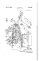
Fig. 3 is a view similar to Fig. 2 showing another position of the parts of the stopping mechanism during the winding operation;
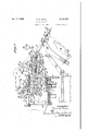
Fig. 4 is a similar view illustrating the manner in which the stopping mechanism acts to arrest the winding operation when the yarn breaks or its supply is exhausted;
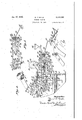
Fig. 5 is a detailed view of a portion of the stopping mechanism illustrating the manner in which the drop-wire or control-lever is automatically reset immediately following the arrestment of the winding operation;
Fig. .6 is a sectional view on line 6'6 of Fig. 2'; 5
Fig. 7 is a sectional viewon line 1--'|.of Fig. 2;
Fig. .8 isasectional plan view on line 88 of Fig. 7; and
Figs. 9, 10, 11 and 12 are sectional views taken on lines 9.9, ins-Ill, ll-ll and l2-l2, respectively, ofFig. 2.
Referring to the drawings, the winding machine herein illustrated is of .the double gang type comprising a plurality of winding units arranged in opposite series along the sides of a horizontal frame or bed 2 supported by suitable legs 3. Spaced along the top of the bed. 2 are a series of brackets or standards 1 which supportcbearings for the driving shaft and other parts of the winding mechanism, two opposite units being located between each pair of brackets but only one unit being herein shown.
As shown most clearly in Figs. 1, 2, 6 and 7 each frame member ."I is constituted by a hollow boxlike central portion .8 bolted to the bed 2 and having an open top. At the bottom of the central portion 8 is a depending arcuate well or reservoir 9 for containing a supply of lubricant indicated at O in the drawings. The member .1 .is provided with an overhanging housing .IEI which communicates with the interior of the central portion 8 while being ofiset with respect thereto. The housing [0 forms a chamber in which the parts of the stopping mechanism are mounted in the manner as later explained. The open top of the member! is closed by an arched cover ll secured in place by screws l2, see Fig. 3, while the open side of the chamber I0 is closed by a cover l3 held in place by a plurality of screws 14 extend ing through holes in bosses on the cover and screwed into threaded holes in bosses on the side of the chamber as shown in Fig. 12. The framemember 1 and .covers H and 13 are'preferably constructed as die-castings to render themstrong n d able. y t l ht in e ght an t efie b economies in manufacture by eliminating costly finishing operations.
In the construction of the machine as shown in Figs. 1 and 2 the winding mechanism comprises only two principal elements, namely: the winding mandrel orspindle |5 on which the yarn-receiver or cop-tube C is rotatably supported; and
the drive-roll 20 for rotating the yam-receiver and in which is embodied the means for traversing the yarn back and forth axially of the package being wound. In this form of construction.
the usual reciprocating thread-guide is dispensed with and the drive-roll has its peripheral surface provided with helical grooves 2| and 22 of opposite hand adapted to receive the strand of yarn toguide it back and forth between the ends of the package. This particular form of traversing means is fully shown and described in United States Letters Patent No. 1,749,355, dated March 4, 1930.
In the preferred form of construction herein shown the drive-roll 20 is carried on and rotated by a horizontal shaft 23 journaled in ball-bearings 24 supported by the brackets 1 and held in place by bearing caps 25; it being noted that the shaft 23 is extended throughout the whole length of the gang machine and may carry the driverolls. for any desired number of winding units.
The present machine is shown as adapted for winding packages of conical form in which the yarn body is built up on any suitable support or receiver, a fiber cop-tube 0 being illustrated in Fig.1 as mounted on a cop-holder l8 rotatable on the winding-spindle l5. As shown most clearly in Fig. 1,'the winding-spindle I5 is swiveled to they forked end of an arm 26 which is carried by a rockable member or support 40 pivoted on a sleeve or bushing 21 enclosing a shaft 35 extending through the frame-members 1.
As shown most clearly in Fig. 6, the sleeve 21 passes through openings in the opposite covers II and hollow frame-members I of one pair in the series and is provided with end-flanges 30 which abut the inner faces of the walls thereof to-hold it from axial displacement. The sleeve 21 is held from rotation in the frame-members 1 by means of set-screws 3| in the covers having their ends seated in longitudinal grooves 32 in the sleeve. It will be understood that a sleeve 21 is positloned between each pair of frame-members 1 and in addition to serving as bushings for the several spindle-arms they provide elongated bearings for the shaft 35 which rotates therein. The shaft 35 extends longitudinally throughout the entire length of the machine and carries a plurality of eccentric disks 36 positioned within the housings 8, one disk being provided for each pair of opposite winding units. The disks 36 are keyed at 31 to the shaft 35 and held axially in place by set-screws 38. Oil 0 is drawn upwardly from the reservoir 9 to lubricate the interior of the sleeves 21 by means of oil-rings 39 suspended on the shaft 35 and depending into the oil supply.
Referring to Fig, 4, the rockable member or support 40, previously described as carrying the spindle-arm 26, is formed with spaced bearings 4| for receiving the rearward reduced end or shank 28 of the arm 26 and a depending hubportion pivoted on the sleeve 21. A collar or hub 5| secured to the shank of the spindle-arm 26 between the bearings 4| serves to hold the arm in place while constituting one element of a builder motion, not herein shown in detail. The hubportionof the support 40 may be split diametrically or constructed in two halves 42 and 43 having abutting projections or arms 44 at one side bound together by means to be later described. At the opposite side the two parts 42 and 43 of the hub are separated by a slit, being clamped together by a binder-screw 45 having its shank passing through a hole in the part 43 and screwed into a threaded hole in the opposite part 42. The hub-portion of the member 40 is thus caused to frictionally grip the sleeve 21 to resist its turning movement thereon to control the swinging movement of the spindle-arm 26 in the manner and for the purpose as later explained. The supporting member 40 may be held in place against the side of the frame-member 1 by means of a collar 52 fixedly secured to the sleeve 21 and constituting a second element of the builder motion.
As a means for applying further resistance to the swinging movement of the arm 26 the present invention makes use of a dash-pot indicated at 59 in Figs. 3, 4 and '7. Spaced plates 41 fastened to the arms 44 of the spindle-arm support 40 form. a fork with a socket 48 therebetween; the arms and plates 41 being fastened together by screws 49. Engaging the socket 48 and slidable thereon is a rectangular block 55 pivotally carried by a pin 56 at the upper end of an elbowshaped connecting link or bar 51. The link 51 is arranged for vertical sliding movement in a guideway 58 formed on the inner face of the cover l3. see Figs. 7 and 8. Attached to the lower horizontally-extending portion of the link 51 is a cylindrical piston or plunger 62. The plunger 62 is slidable in a well or cylinder 64 formed in the bottom or floor of the frame-member 1 and is flattened along one side to provide a restricted vent 65 from the cylinder 64 to permit oil 0 to escape from and flow into the cylinder as the plunger 62 is raised and lowered therein. As the spindle-arm 26 is lowered resistance is offered to this movement due to the restricted opening or vent 65 and, as a result, the package or coptube, as the case may be, is brought slowly into contact with the rotating drive-roll 20 to provide for starting the rotation of the package slowly so as not to strain or break the yarn.
When the winding machine is inoperative the spindle-arm 26 is held in raised position by the engagement of the end of a horizontally extending latch or detent-bar 10 in a notch 1| in the side of the connecting link 51, see Fig. 4. The detentbar 10 is slidable in spaced bearings 12 on the inner face of the cover l3, see Fig, 9, and is urged into engagement with the notch 1| by a coilspring 13 having one end anchored to a pin 14 on the cover and its opposite end hooked around a pin 15 depending from the bar. The bar 10 is adapted to be withdrawn from engagement with the slot 1| by the movement of a pivoted starting lever 18 within the housing If). As shown in Figs. 3 and 10, the lever 18 is fastened by a set screw 82 to a transverse shaft 19 pivotally mounted in bearings and 8| on the housing I!) and cover l3 respectively. The shaft 19 is constituted as the bent end of a starting handle 85 which reaches upwardly and forwardly and has a knob or other hand-rest 86 at its end adapted to be conveniently grasped by the operator of the machine. When the handle 85 is depressed the starting lever 18 is rocked in a clockwise direction, as viewed in Fig. 4, and through the engagement of its upper offset end with an abutment 83 on the detent-bar 10 the latter is slid forwardly to release it from engagement with the slot 1| to allow the spindle-arm 26 to descend under the action of gravity. The handle 85 is normally held in raised position by a coil-spring 80 having one end hooked through a hole in the lever 18 and its .other end anchored to a pin 09 on the housing I0. An arm 90 integral with the starting lever 18 engages the bottom wall of the housing I to limit the movement of the lever and thereby that of the handle 85.
A stop is provided for limiting the downward movement of the spindle-arm 26 to prevent the cop-holder I8 from contacting with the driveroll 20 to score or otherwise damage the surface of the latter when the cop-tube C is removed from the spindle. As shown in Figs. 1 and 2, the stop comprises a set-screw 9i screwed into a boss 92 on the side of the cover I3 with its head adapted to engage the under side of the lower projection 44 on the hub 40 of the spindle-arm 26. The screw 9| may be adjusted vertically in the boss 92 and locked in adjusted position by a check-nut 03.
The stopping mechanism which operates to raise the spindle I away from the drive-roll 20 to arrest the winding when the yarn breaks or its supply is exhausted comprises an intermittently operated mechanism constructed and arranged as next described. Referring to Fig. 6, the sides of the housing or chamber I0 are provided with alining holes 95 for receiving circular bosses 90 on the inner walls of the opposite covers i3. Mounted for pivotal movement in axial holes in the bosses 90 is a transverse shaft or pivotrod 91. A walking beam or oscillator I00 has its hub IOI pivoted on the shaft 9'1 and is formed with opposite arms I02 radiating from the hub. Above the hub I0! the oscillator I05 is bifurcated as shown in Figs. 3 and 4 with the sides I03 of the bifurcation arranged to straddle the periphery of the eccentric or cam v3E5 to cause the oscillator to be continuously rocked therefrom during the rotation of the eccentric.
The oscillator I00 acts to operate the stopping mechanism of two opposite winding units by means of its opposite arms I02, but it will be sufficient to describe the mechanism of one unit only. Pivoted on a stud I05 in the end of the arm I02 is a bell-crank lever I06, see Figs. 3, 4 and 5, one arm 50! of which is provided with a slot I08 in its side. Engaged in the slot I 08 is a rectangular block I00, see Fig. 7, pivotally mounted on a pin H0 projecting from the side of the vertical link 51. The other arm II2 of the bell-crank lever I06 carries a stud H3, see Fig. 11, to which is pivotally connected one end of a horizontal bar H5. The outer free end of the bar H5 rests on a roller H0, see Figs. 4 and 10, rotatable on the starting lever shaft 19 and is formed on its upper surface with a shoulder ill. As the oscillator I00 is rocked under the action of the eccentric disk 30 the bell-crank lever I06 is raised and lowered bodily with respect to the block I09. With the cop-tube C or the package resting against the drive-roll 20 the block I29 is relatively fixed and the bell-crank lever I00 is thus caused to pivot on the stud I05 to slide the bar I I5 forwardly and rearwardly across the roller H0. This movement of the parts is continuous until the yarn breaks or its supply is exhausted, at which time the bar I I5 is restrained from moving forwardly, thus causing the bellcrank lever I00 to pivot on the stud I05 to rock its arm I01 upwardly tothe position shown in Fig. 4, during the upward movement of the lever. The arm I01 of the lever I06 is engaged with the block I09 in its groove I08 andconsequently the link 51 is raised to elevate the spindle-arm 26 through the instrumentalities before described.
The detent-means for restraining the bar H5 from forward movement comprises a pawl I20 having a toe .I2.I for engaging the shoulder II! on the bar. As shown in Fig. 1, the pawl I20 is fast on the inner end of a pivot-rod I22 extending through a bearing boss I23 on the housing cover I3. At the outer threaded end of the rod I22 is a pair of plates or washers I24, between which is held the hooked end of an elbow-shaped breakage-lever or drop-wire I25. Nuts I26 screwed onto the rod I22 and set up against the plates I24 bind the lever I25 fixedly to the rod. The breakage-lever I25 extends forwardly and downwardly and terminates in a right-angular bent portion or crossbar I21 which. lies parallel to the axis of the drive-roll 20.
The yarn, indicated at 11, passes over the end portion E2! of the lever I25 and tends to depress the latter to normally maintain the toe I2I of the pawl I20 raised out of the path of movement of the bar H5. During the normal operation of the machine the crossbar I 2'! rests against a shelf or ledge I29 formed at the upper end of a tension bracket I30, see Figs. 2, 3 and 4, which is mounted on a rail I34 extending along the side of the machine; the rail I34 being supported from the legs 3 by spaced brackets I35. The yarn y draws upwardly from a supply-bobbin B, held on a spindle I3! adjustably mounted on the bracket I 30, and passes through a tension-device, indicated generally by the reference character I40, thence through a suitable slub-catcher, shown at I4I, and under a horizontal guide-wire I42. From the wire I42 the yarn draws across the bail I21 and leads upwardly to feed through the grooves of the traverse-roll 20 to traverse it on the package being wound. When the yarn breaks or its supply is exhausted it releases the lever I25 which swingsupwardly due to the weight of the toe I 2i of the pawl I20. The toe I2I of the pawl I20 is thus caused to engage the shoulder II! on the reciprocating bar H5 to effect arrestment of the winding operation in the manner as previously explained.
In winding machines of previous types wherein pivoted bails, levers or drop-wires are employed as the means for initiating the action of the stopping mechanism it has heretofore been necessary to manually reset these devices either during or after the rethreading or tying-in operation. In most cases this necessitates that the operator use one hand to hold the drop-wire or other control means inoperative until the slack in the yarn is taken up by the winding while the starting means is manipulated with the other hand. According to the present invention means are provided for automatically resetting the control means and maintaining it inoperative during the rethreading or tying-in operation and during restarting of the winding unit. In the present embodiment of the invention this means consists in a three-armed lever I45, see Figs. 2, 3 and 4, pivoted on a stud I45 screwed into a boss I41 on the interior of the housing I0 as shown in Fig. 9. The upper end of the vertical arm I48 of the lever I45 extends laterally into position to be engaged by an abutment I50 on the side of the detent-bar I0 for a purpose as later explained. The forwardly-extending arm I50 of the lever M5 is offset downwardly and its end rounded to adapt it to engage against the under side of the pawl I20. The opposite or rearward arm I5I .of the lever I45 is provided with a suitable weight I52 which tends to swing the lever in a counterclockwise direction as viewed in Fig. 3 to raise the pawl I20 to disengage it from the shoulder III on the bar II5 and carry the end I2I of the lever I25 downwardly against the rest or shelf I29 as illustrated in Fig. 5. If, for any reason, the lever I45 should fail to perform its intended function the pawl I20 will be returned to initial position during the restarting of the winding by reason of the engagement of the end of the detentbar I0 with an upwardly directed arm I55 on the pawl. An abutment I56 on the end wall of the housing serves as a stop for limiting the pivotal movement of the pawl I20 and thereby the forward sliding movement of the latch or detent-bar I0, The improved stopping mechanism of the winding machine having been described in detail its method of operation will next be explained.
To prepare the winding unit for operation a suitable paper or fiber cop-tube or other yarnreceiver C is placed on the spindle I5 while the latter is in raised position as shown in Fig. 4. The yarn y is next drawn upwardly from the supply-bobbin B, passed through the tensiondevice I40 and slub-catcher MI, and threaded beneath the guide-wire I42. From the guidewire I42 the yarn is led across the crossbar I2'I of the breakage-lever or drop-wire I25 which rests upon the shelf I29, passed across the driveor traverse-roll 20 and its end attached to the cop-tube C. The unit is then ready to start the operation of winding a package.
The two shafts 23 and 35 are constantly rotated by suitable driving means, not herein shown, and the oscillator I00 is continuously rocked by the eccentric disk 36 on the shaft 35. The bell-crank lever I06 is thus caused to be raised and lowered bodily and due to its engagement with the block I09 it is rocked to reciprocate the bar II5. Now, since the pawl I20 is held inoperative by the forward end of the weighted lever I45 the bar simply rides back and forth over the roller II6 without hindrance. To start the winding the starting handle 85 is depressed, thereby rocking the lever I8 to shift the detent-bar I9 forwardly to disengage its inner end from the notch II in the vertical connecting link 51. The spindle-arm 26 is thus released to cause it to descend to lower the cop-tube C into surface contact with the periphery of the roll 20. The arm 26 is lowered gradually, due to the resistance offered by the dash-pot 50, and the tube C is brought gently into contact with the roll 20. Through this provision the winding is started slowly without causing undue strain on the yarn. The frictional grip of the split hub of the spindle-arm support 40 on the sleeve 21 compensates for any slack or looseness that may occur between the elements and thus assists in effecting the gradual lowering of the spindle without chattering or vibration of the parts.
As the yarn-receiver C is brought into surface contact with the periphery of the drive-roll 20 it will be rotated from the roll to wind on the yarn. The roll 20 turns in the direction indicated by the arrow in Fig. 2 and as the yarn is taken up by the rotation of the receiver C the strand y will enter one or the other of the helical grooves 2I and Hon the periphery of the roll. As the yarn feeds through the grooves it is traversed back and forth longitudinally of the receiver C to build up a succession of courses forming overlying layers which constitute the yarn body or package.
It quite often happens that the cop-tube or other yarn-receiver is irregular in shape, for instance, its periphery may be out of round or eccentric with respect to the axis of the spindle upon which it is mounted. When this condition exists the receiver tends to bounce or jump on the drive-roll to cause an uneven draft on the yarn liable to strain the material, and also liable to form an irregular-shaped package. By the use of the dash-pot the receiver C is prevented from such bouncing or vibrating on the driveroll. The double-action of the dash-pot provides for retarding both the upward and downward movement of the cop-holder or winding mandrel I8 to maintain it substantially in a state of equilibrium to effect better traction of the package on the drive-roll throughout the winding of a complete package.
At the start of the winding the block I09 is carried to its lowermost position as illustrated in Figs. 2 and 3 and as the oscillator I00 is constantly rocked and the bell-crank lever I06 raised and lowered thereby the sliding engagement of the block in the groove I08 of the bell-crank lever causes the latter to rock on the stud I05 from the position illustrated in Fig. 2 to that shown in Fig. 3. This latter motion of the lever I06 causes the bar II5 connected to its arm II2 to be continuously reciprocated forwardly and rearwardly across the roller II6.
If the yarn y breaks or its supply is exhausted the crossbar I2I of the lever I25 is released to allow the lever to swing upwardly under the weight of the pawl I20. The toe I2I of the pawl I20 will then drop onto the end of the bar I I5 into position to engage its shoulder II! at the next forward movement of the bar. As the bar I I 5 is moved forwardly at the next upward stroke of the arm I02 of the oscillator I00 the toe I2I of the pawl I20 engages the shoulder I I! to restrain the bar from further movement in this direction. Now, as the arm I02 of the oscillator I00 continues to rock upwardly, the bar I I5 acts on the arm I I2 of the bell-crank lever I06 to cause the latter to rock about the stud I05 in the clockwise direction as viewed in Fig. 4, whereby it acts to raise the block I09 to slide the link 51 upwardly to raise the spindle-arm 26. The package is thus removed from contact with the roll 20 to arrest the wind ing.
Immediately the notch II in the link 51 registers with the end of the detent-bar or latch I0, the spring I3 shifts the bar rearwardly into the notch to hold the arm 26 in elevated position. The
rearward movement of the detent-bar I0 carries the abutment I49 away from the upper arm I48 of the weighted lever I45 and the end of its arm I50 is brought up against the under side of the pawl I20. At the next rearward stroke of the bar II5 the toe I2I of the pawl I20 is released from the shoulder I I1 and under the action of the lever I45 the pawl is swung upwardly to the posi tion shown in Fig. 5 to carry the crossbar I2I of the control-lever or drop-wire I25 down against the shelf I29 on the bracket I30. The control means for the stop-motion is thus automatically reset and the pawl I20 held inoperative to prevent its engagement with the constantly reciprocating To restart the winding machine the yarn is pieced up and the package again lowered into driving contact with the drive-roll 20 by simply depressing the handle 85. During the piecing-up of the ends of the yarn the drop-wire I25 is held inoperative by the lever I 45 and thus the operator may use both hands for this work. Moreover, during the restarting of the machine only one hand is needed as no attention is required to be given to the drop-wire or control lever I25. For these reasons the machine may be more conveniently and expeditiously tended and its productive capacity is thereby substantially increased. As the starting handle 85 is depressed and the detent-bar l0 drawn forward its abutment I49 engages with the upper arm I48 of the lever I45 to lower its arm I50 and thereby release its pressure against the pawl I20 to permit the latter to drop when the yarn again breaks or its supply is exhausted. Through the engagement of the outer end of the detent-bar I0 with the projection I of the pawl i20 the toe I2I of the latter is maintained in raised position as long as the starting handle 85 is held depressed. In this manner the stopping mechanism may beheld inoperative until the slack in the yarn is taken up by the Winding.
It has been explained that at the start of the winding the block I09 is in its lowermost position as shown in Figs. 2 and 3. During the growth of the package the block I00 is raised gradually and consequently the. bar H5 is slid rearwarclly to a constantly increasing extent and carried forwardly with a constantly decreasing motion. Regardless of this change in the extent of movement of the bar I I5, however, its forward movement will be restrained by the pawl I20 so that the spindle-arm 26 is always raised to the position shown in Fig. 4.
It will be observed from the foregoing that the present invention provides a winding machine having improved means for manually starting and automatically arresting the winding operation when the winding strand breaks or its supply is exhausted. The present stopping mechanism is extremely simple in construction, yet highly efficient and rapid in action to perform its intended function. The parts of the mechanism are entirely enclosed to prevent the accumula tion of dust or lint thereon Which would tend to hinder its action and render it less effective.
As another feature of improvement, means incorporated in the stopping mechanism act automatically to return the control means to initial position whereby to leave the operators hands free to perform other duties.
The invention further provides means for effecting slow or gradual starting of the winding operation to avoid sudden draft on the yarn liable to break or strain the material. This means also acts to prevent jumping or bouncing of the package on the drive-roll and thus maintains the driving traction more constant and uniform.
While the improved winding machine is herein shown and described as embodied in a preferred form of construction, it is to be understood that various modificationsmay be made in the structure and arrangement of its mechanism without departing from the spirit or scope of the invention. Therefore, without limiting myself in this respect, I claim:
1. In a winding machine, stopping mechanism for arresting the winding operation, a member pivotally connected to the stopping mechanism,
a second pivot for said member spaced from its pivotal connection to the stopping mechanism, means for oscillating said member about its pivotal connection with the stopping mechanism, and yarn-controlled means operative when the yarn breaks or its supply is exhausted to cause the member to rock about the second-mentioned pivot to operate the stopping mechanism.
2. In a winding machine, stopping mechanism for arresting the Winding operation, intermittently-operating mechanism including an oscillating member pivoted to the stopping mechanism and adapted to normally rock on the latter, a second pivot for the oscillating member spaced from its pivotal connection to the stopping mechanism, and yarn-controlled means operative when the yarn breaks or its supply is exhausted to cause the member to rock about the second-mentioned pivot to operate the stopping mechanism.
3. In a winding machine of the type in which the package is rotated by peripheralcontact with a drive-roll, stopping mechanism comprising means for moving the package away from the drive-roll, an oscillator, a member pivotally connected to the oscillator, one end of said member being pivotally connected to the means for moving the package, and yarn-controlled means operative when the yarn breaks or its supply is exhausted to hold the opposite end of the member as it is rocked by the oscillator to cause it to actuate the means for moving the package to arrest the winding operation.
4. In a winding machine of the type in which the package is rotated by peripheral contact with a drive-roll, stopping mechanism comprising means for moving the package away from the drive-roll, an oscillating member pivotally connected to said means, means to oscillate said member, said member normally rocking about its pivotal connection with the means for moving the package, a second pivot for the oscillating member spaced from its first-mentioned pivotal connection, and yarn-controlled means operative when the yarn breaks or its supply is exhausted to cause the oscillating member to rock on its second pivot to operate the means for moving the package away from the drive-roll.
5. In a winding machine of the type in which the package is rotated by peripheral contact with a drive-roll, stopping mechanism comprising means for moving the package away from the drive-roll, intermittently operating mechanism including an oscillating member pivotally connected to said means and adapted to normally rock on the latter, and yarn-controlled means including a slide pivotally connected to theoscillating member and operative when the yarn breaks or its supply is exhausted to hold the slide and cause the oscillating member to rock about its pivotal connection therewith to operate the means for moving the package away from the drive-roll.
6. In a winding machine of the type in which the package is rotated by peripheral contact with a drive-roll, stopping mechanism comprising an element for moving the package away from the drive-roll, an oscillating member pivotally connected to said element, means for continuously rocking the oscillating member about its pivotal connection with said element, a slide pivotally connected to the oscillating member and normally reciprocated thereby, and means controlled by the yarn and operative when the yarn breaks or its supply is exhausted to hold the slide and thereby cause the oscillating member to rock about its pivotal connection therewith and operate the package-moving element. V
'7. In a winding machine of the type in which the package is rotated by peripheral contact with the drive-roll, stopping mechanism comprising a bar for moving the package away from the driveroll, an oscillating member pivotally mounted intermediate its ends and having one end pivotally connected to the bar; a slide pivotallyconnected to the oppositeend' of the oscillating member, means for Continuously oscillating the pivotal mounting of the oscillating member to cause the latter to rock about its pivotal connection with the bar and to reciprocate the slide, and means controlled by the yarn and operative when the yarn breaks or its supply is exhausted to hold the slide and thereby cause the oscillating member to rock about its pivotal connection therewith to operate the bar. 7
8. In a winding machine of the type in which the package is rotated by peripheral contact with a drive-roll, stopping mechanism comprising means for' moving the package away from the drive-roll, an oscillating member pivotally mounted intermediate its ends and having one end pivotally connected to the means for moving the package, a slide pivotally connected to the opposite end of the oscillating member, and means normally held inoperative. by the yarn and adapted to automatically engage the slide when the yarn breaks or its supply is exhausted to cause the oscillating member to rock about its pivotal connection with the slide to thereby operate the means for moving the package.
9. In a winding machine of the type in which a package is rotated by peripheral contact with a drive-roll, stopping mechanism comprising means for moving the package away from the drive-roll, an'oscillator, means to actuate the oscillator, a bell-crank carried by the oscillator and having one arm connected tothe packagemoving means, a slide connected to the opposite arm of the bell-crank and adapted to be reciprocated as the bell-crank is rocked by the oscillator about its pivotal connection with the packagemoving means, and yarn-controlled means operativewhen the yarn breaks or its supply is exhausted to engage the slide to cause the bellcrank to rock about its pivotal connection with the slide and thereby operate the package-moving means. .7
1Q. In a winding machine, the combination of a drive-roll, means for supportinga package in contact with the drive-roll, means for moving the package away from the drive-roll, a member mounted to normally rock about one pivot without operating said means and to rock about a secondpivot to operate said means, yarn-controlled means operative when the yarn breaks or. its supply is exhausted tocause the member to rock about its second pivot to operate the means for moving the package away from the drive-roll to arrest the winding operation, and means 'for latching the package-moving means in position to hold the package away from the drive-roll.
11, In a winding machine, the combination of a'drive-roll, means for supporting a package in contact with the drive-roll, a'bar for moving the package away from the drive-roll to arrest the winding operation, an oscillating member pivotally connected to said bar, a second pivot for theoscillating'member spaced from its pivotal connection to the bar, yarn-controlled means operative when the yarn breaks or its supply is exhausted to cause the oscillating member to rock about its last-named pivot to move the bar, a latch for engaging the bar, a spring for holding the latch inengagement with the bar-to maintainthe package away from the drive-roll, and
manually-operative means for releasing the latch to start a winding operation.
12. In a winding machine, the combination of a frame having hollow standards arranged in spaced relationship, a shaft journaled in said standards, drive-rolls carried by said shaft, means on said standards for supporting packages in contact with the drive-rolls, and stopping mechanism enclosed in the hollow standards including means for moving the packages away from their drive-rolls, means for operating said means, and yarn-controlled means for controlling the oper ating means.
13. In a winding machine of the type in which the package is rotated by peripheral contact with a drive-roll, a hollow frame, and stopping mechanism enclosed in the hollow frame comprising means for moving the package away from the drive-roll, a member pivoted to said means, a second pivot for said member spaced from its pivotal connection with said means, means for oscillating said member about its pivotal connection with said means, and yarn-controlled means operative when the yarn breaks or its supply is exhausted to cause the oscillating member to rock about the second-mentioned pivot to operate the means for moving the package away from the drive-r'oll.
14. In a winding machine, a hollow frame, a drive-roll mounted to rotate on the frame, an arm pivotally mounted on the frame, a packagesupporting spindle on the arm, a bar connected to the spindle-carrying arm for raising the latter to arrest a winding operation, means for moving the bar, 'a piston connected to the bar, and a well in the hollow frame having a cylinder cooperating with the piston to form a dash-pot for retarding the movement of the package toward and away from the drive-roll. v
15. In a winding machine, the combination of a drive-roll, means for supporting a package in contact with the drive-roll, means connected to the package-supporting means for moving the package away from the drive-roll to arrest the winding operation, a dash-pot connected to said means for moving the package-supporting means to retard its movement, an oscillating member pivotally connected to said means and normally rocking on the latter, a second pivot for the oscillating member spaced from the first pivot, and yarn-controlled means operative when the yarn breaks to cause the oscillating member to rock about its second pivot to operate the means for moving the package.
16. In a winding machine, a frame having a hollow-standard, a shaft journaled on said standard, a drive-roll carried by said shaft, means movably mounted on said standard for supporting a package in contact with the drive-roll, stopping mechanism enclosed in said hollow standard comprising a bar connected to the means for supporting the package, said bar having a piston at its end, a cylinder in the standard cooperating with the piston to form a dash-pot, an oscillating pivotally connected to the bar, a second pivot for the oscillating member spaced from its pivotal connection with the bar, and yarn-controlled means in the standard operative when the yarn breaks or its supply is exhausted to cause the oscillating member to rock about the secondmentioned pivot to operate the bar.
1'7. Ina winding machine, stopping means for arresting the winding operation, said stopping means having an oscillating member, a yarncontrolled lever pivotally mounted intermediate its ends, one end of said lever being engaged by the yarn to maintain the lever in inoperative position, said lever being operative when the yarn breaks or its supply is exhausted to engage the oscillating member to operate the stopping means, and means controlled by the stopping means and operative after the latter has been actuated to reset the lever to inoperative position.
18. In a winding machine, stopping means for arresting the winding operation, a drop-wire normally held in inoperative position by the yarn and operative when the yarn breaks or its supply is exhausted to actuate the stopping means, means controlled by the stopping means and operative after the latter has been actuated to reset the drop-wire, and manually-operative starting means acting to move the means for resetting the drop-wire to an inoperative position and to engage the drop-wire to hold it until the yarn is tensioned by the winding operation.
19. In a winding machine, the combination of a drive-roll, means for supporting a package in contact with the drive-roll, stopping means for moving the package away from the drive-roll including a reciprocating member, a drop-wire normally held in inoperative position by the yarn and operative when the yarn breaks to engage the reciprocating member to actuate the stopping means, means controlled by the stopping means and operative after the latter has been actuated, and manually-operated starting means operative to move the resetting means for the drop-wire to an inoperative position and to engage the dropwire to hold it until the yarn is tensioned by the winding operation.
20. Ina winding machine, the combination of a drive-roll, means for supporting a package in contact with the drive-roll, means for moving the package away from the drive-roll, intermittently operating mechanism including an oscillating member pivotally connected to said package-moving means, a slide pivotally connected to the oscillating member, a control lever normally held in inoperative position by the yarn and operative when the yarn breaks or its supply is exhausted to engage the slide to cause the oscillating member to rock thereon and actuate the packagemoving means to release the package from the drive-roll, and means for automatically resetting the control lever to inoperative position.
21. In a winding machine, a drive-roll, means for supporting a package in contact with the drive-roll, intermittently operating means connected to the package-supporting means for moving the package away from the drive-roll to arrest the winding operation, said operating means including a reciprocating slide, a control-lever normally held in inoperative position by the yarn, interengaging means on said lever and slide operative when the yarn breaks to cause the operating means to move the package away from the drive-roll, and means operative thereafter to reset the control lever in inoperative position.
22, In a winding machine, a drive-roll, means for supporting a package in contact with the drive-roll, stopping mechanism for moving the package away from the drive-roll to arrest the winding operation, a yarn-controlled lever for controlling the operation of the stopping mechanism, a latch automatically operative to hold the package away from the drive-roll, a trip member controlled by the latch and operative to reset the control-lever, and manually-operative means for withdrawing the latch and moving the trip member to inoperative position.
23. In a winding machine, a drive-roll, means for supporting a package in contact with the drive-roll, means for moving the package away from the drive-roll to arrest the winding operation, intermittently operating mechanism connected to operate the package-moving means, a yarn-controlled lever cooperating with the package-moving means when the yarn breaks to operate the latter, a latch-bar engaging the packagemoving means to hold the package away from the drive-roll, a gravity operated trip member controlled by the latch-bar and operative after the latch-bar has moved into engagement with the package-moving means to reset the control-lever, and a starting handle for withdrawing the latchbar from engagement with the package-moving means and setting the trip lever in inoperative position.
24. A winding machine comprising a horizontal bed, and a series of parallel laterally-extending hollow brackets mounted on said bed in spaced relationship therealong, said brackets carrying bearings at one side of the bed, a shaft journaled in the bearings, drive-rolls on said shaft, bearings on the brackets at the center of the bed, a second shaft journaled in the central bearings, means for supporting packages in contact with the drive-rolls, and stopping mechanism in the hollow brackets operated from the second shaft for lifting the package-supporting means away from the drive-rolls.
25. A winding machine comprising a horizontal bed, and a plurality of brackets extending laterally of the bed, each of said brackets formed with a hollow compartment having an oil reservoir therein and an opening at its side, a bearing on each bracket, a horizontal shaft journaled' in the bearings on the brackets, drive-rolls on said shaft, covers for covering the openings on the side of the brackets, means for supporting packages in contact with the drive-rolls, and a stopping mechanism in the hollow compartment of each bracket for lifting the adjacent packagesupporting means away from its respective driveroll.
DAVID E. MILLS.
CERTIFICATE OF CORRECTION. Patent No. 2,11 19192. January 17, 1959.
DAVID E MILLS It is hereby certified that error appears in the printed specification of the above numbered patent requiring correction as follows: Page 6, second column, line 61;, claim 16, after oscillating insert the word member; page 7, first co1umn,.line 50, claim l9,after "actuated" and before the comma insert to reset the drop-wire; and that the said Letters Patent should be read with this correction therein that the same may conform to the record of the case in the Patent Office.
Signed and sealed this 7th day of March, A. D. 1.959..
Henry Van Arsdale.
(Seal) ,Acting Commissioner of Patents.,
Priority Applications (1)
| Application Number | Priority Date | Filing Date | Title |
|---|---|---|---|
| US107098A US2144192A (en) | 1936-10-22 | 1936-10-22 | Winding machine |
Applications Claiming Priority (1)
| Application Number | Priority Date | Filing Date | Title |
|---|---|---|---|
| US107098A US2144192A (en) | 1936-10-22 | 1936-10-22 | Winding machine |
Publications (1)
| Publication Number | Publication Date |
|---|---|
| US2144192A true US2144192A (en) | 1939-01-17 |
Family
ID=22314822
Family Applications (1)
| Application Number | Title | Priority Date | Filing Date |
|---|---|---|---|
| US107098A Expired - Lifetime US2144192A (en) | 1936-10-22 | 1936-10-22 | Winding machine |
Country Status (1)
| Country | Link |
|---|---|
| US (1) | US2144192A (en) |
Cited By (3)
| Publication number | Priority date | Publication date | Assignee | Title |
|---|---|---|---|---|
| US2740589A (en) * | 1951-05-04 | 1956-04-03 | Universal Winding Co | Winding machine |
| US3563480A (en) * | 1967-09-21 | 1971-02-16 | Roannais Constr Textiles | Apparatus for stopping a takeup bobbin |
| ITMI20120480A1 (en) * | 2012-03-27 | 2013-09-28 | Savio Macchine Tessili Spa | BRAIDED ARM FOR THE WINDING OF ROCKS YARN |
-
1936
- 1936-10-22 US US107098A patent/US2144192A/en not_active Expired - Lifetime
Cited By (4)
| Publication number | Priority date | Publication date | Assignee | Title |
|---|---|---|---|---|
| US2740589A (en) * | 1951-05-04 | 1956-04-03 | Universal Winding Co | Winding machine |
| US3563480A (en) * | 1967-09-21 | 1971-02-16 | Roannais Constr Textiles | Apparatus for stopping a takeup bobbin |
| ITMI20120480A1 (en) * | 2012-03-27 | 2013-09-28 | Savio Macchine Tessili Spa | BRAIDED ARM FOR THE WINDING OF ROCKS YARN |
| EP2644549A1 (en) * | 2012-03-27 | 2013-10-02 | Savio Macchine Tessili S.p.A. | Winding machine |
Similar Documents
| Publication | Publication Date | Title |
|---|---|---|
| US3350021A (en) | Thread winding machine | |
| US2144192A (en) | Winding machine | |
| US1958060A (en) | Stop motion | |
| US2135485A (en) | Machine for preparing yarn packages | |
| US2165018A (en) | Winding machine | |
| US1799153A (en) | Winding machine | |
| US2200388A (en) | Traverse mechanism for yarnwinding machines | |
| US2594509A (en) | Textile device | |
| US2154847A (en) | Attachment for winding taper ended packaces | |
| US1727884A (en) | Winding machine | |
| US3012734A (en) | Winding machine with load size thread snag | |
| US2665077A (en) | Stop motion for yarn winding machines | |
| US1845565A (en) | Stop mechanism for yarn twisting and winding machines | |
| US2131470A (en) | Yarn winding machine | |
| US1895741A (en) | Winding machine | |
| US2743063A (en) | Stop-motion for winding and like machines | |
| US1959567A (en) | Yarn winding device | |
| US3044722A (en) | Winding machine | |
| US1583243A (en) | Winding machine | |
| US756014A (en) | Machine for winding yarn. | |
| US514884A (en) | Spooling-machine | |
| US26415A (en) | Machine for winding thread on spools | |
| US1208295A (en) | Warping apparatus. | |
| US1955778A (en) | Winding machine | |
| US1028609A (en) | Winding-machine. |