US2139282A - Gauging device - Google Patents
Gauging device Download PDFInfo
- Publication number
- US2139282A US2139282A US119293A US11929337A US2139282A US 2139282 A US2139282 A US 2139282A US 119293 A US119293 A US 119293A US 11929337 A US11929337 A US 11929337A US 2139282 A US2139282 A US 2139282A
- Authority
- US
- United States
- Prior art keywords
- gauging
- work piece
- sleeve
- pressure
- fluid
- Prior art date
- Legal status (The legal status is an assumption and is not a legal conclusion. Google has not performed a legal analysis and makes no representation as to the accuracy of the status listed.)
- Expired - Lifetime
Links
Images


Classifications
-
- G—PHYSICS
- G01—MEASURING; TESTING
- G01B—MEASURING LENGTH, THICKNESS OR SIMILAR LINEAR DIMENSIONS; MEASURING ANGLES; MEASURING AREAS; MEASURING IRREGULARITIES OF SURFACES OR CONTOURS
- G01B13/00—Measuring arrangements characterised by the use of fluids
- G01B13/16—Measuring arrangements characterised by the use of fluids for measuring contours or curvatures
-
- G—PHYSICS
- G01—MEASURING; TESTING
- G01B—MEASURING LENGTH, THICKNESS OR SIMILAR LINEAR DIMENSIONS; MEASURING ANGLES; MEASURING AREAS; MEASURING IRREGULARITIES OF SURFACES OR CONTOURS
- G01B13/00—Measuring arrangements characterised by the use of fluids
- G01B13/08—Measuring arrangements characterised by the use of fluids for measuring diameters
- G01B13/10—Measuring arrangements characterised by the use of fluids for measuring diameters internal diameters
-
- Y—GENERAL TAGGING OF NEW TECHNOLOGICAL DEVELOPMENTS; GENERAL TAGGING OF CROSS-SECTIONAL TECHNOLOGIES SPANNING OVER SEVERAL SECTIONS OF THE IPC; TECHNICAL SUBJECTS COVERED BY FORMER USPC CROSS-REFERENCE ART COLLECTIONS [XRACs] AND DIGESTS
- Y10—TECHNICAL SUBJECTS COVERED BY FORMER USPC
- Y10S—TECHNICAL SUBJECTS COVERED BY FORMER USPC CROSS-REFERENCE ART COLLECTIONS [XRACs] AND DIGESTS
- Y10S33/00—Geometrical instruments
- Y10S33/02—Air
Landscapes
- Physics & Mathematics (AREA)
- General Physics & Mathematics (AREA)
- Measuring Fluid Pressure (AREA)
Description
GAUGING DEVICE Filed Jan. 6, 1937 3 'Sheets-Sheet 1 -I I vgNTo ATTORNEY Dec.'6, 1938.` 1 F. PoocK Er Al. .2,139,282
GAUGING DEVICE Filed Jan. 6, 1937 3 Shf-.eetS--Sheei'l 2 De- 6, 193.8- l.. F. PoocK ET AL 2,139,282
` GAUGING DEVICE Filed Jan. 6, 1957 3 Sheets-Sheet 3 12 i M5 J5 (7 l7 lNvE R 4 17 W@ MMX/M 1/ )20v ATTORNEY Patented 6, 1938 UNITED fsrATl-:S
PATENT or-Fice 2.139.282 GAUGING nevica maar. rmx mawmis ray Auer, mmm om.
usignors to VThe Sheffield Gage Corporation, Dayton, Ohio, a corporation of Ohio Application January 6,
4Claims.
-from an accepted size standard by measure of fluid leakage between the work piece and a gauging element with which the work piece interflts during the gauging operation.
Another object of the invention is the, provision I of such av gauging device that is readily adjustable to a desired degree ofl sensitivity.
Another object of the invention 'is the provision of such a, gauging device having readily replaceable gauging elements'to afford a wide range of gauging operations, and readily adjust-` able iiuid flow controlling devices for coordinating the ow conditions to the particular gauging -operation to be performed.
A further object of the invention is the provision of a gauging element that measures size variation in terms of fluid leakage and comprises a sensitivity determining flow passage arranged as an elongated groove on one of thev engaging faces of a pair of telescopically interfitting meml bers of which one member interiits the piece to Cai be gauged. A
Still another object of the invention is the provision of a gauging element for `cooperation with the cylindrical surface of a work piece to concomitantly gauge the straightness of the work piece surface as well as its deviation from-apredetermined diameter.
Another object of the invention is the provision of a gauging device utilizing iiuid having a pressure differing from atmospheric pressure as a gauging medium and functioning by a measure of huid leakage to indicate an out of round condition in a cylindrical surface.
Other objects and advantages of the invention will be apparent from the following description,
the accompanying drawings and the appended claims.
In the drawings, in which is disclosed preferred embodiments of the invention,-
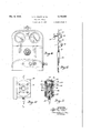
`Fig. 1 is-a plan view of one form of the gaugling device;
Fig. 2 is a vertical sectional view taken on the line 2-2 of Fig. 1;
lFig. 3 is a transverse sectional view as indi cated by the line 3--3 on Fig. 2; Fig. 4 is a transverse sectional view, as indi- 'l A'cated by the line Q-I on Fig. 2;
1931, serial No. 119,29:
(ci. ca -17s) Fig. 5 is a transverse sectional view as indicated by the line 5-5 on Fig. 2;
Fig. 6 is an end elevational view of the device shown in Figs. 1 and 2;
Fig. 'i is a sectional view corresponding in positioning to Fig. 2 and illustrating a differentrform of the gauging device;
Fig. 8 is a transverse section as indicated by the line 8-8 on Fig. '1;
Fig. 9 is a plan view generally similar to Fig. 1
and illustrating a further modification of the gauging device;
Fig. 10 is an elevational view showing a further modification of the gauging device;
l Fig. 11 is' a sectional view as indicated by the line II--II on Fig.` 10; and
Fig. 12 is a diagrammatic showing of the uid iiow connections utilized in the gauging device.
The drawings, in which like characters of reference designate like parts throughout the several views thereof, show several modifications of a gauging device wherein fluid havinga pressure differing from atmosphericpressure is utilized as a gauging medium. The gaugng'device incorporates a gauging element that is adapted to receive a work piece in interiitting engagement. The element has a fluid outlet of which the effective opening is varied by the fit of the work piece so that a reading may be taken of the vwork piece size in terms of fluid leakage. In the illustrated embodiments of the invention a single arrangement of fluid `flow connectionshas been provided to which gauging elements of different character lmay be attached so that a. Wide range of gauging operations may be performed on the device.
Referring now in general terms to the gauging device, there is provided a framework or housing III which serves as-an enclosure for the various fluid flow connections and as a supporting structure for the several parts of the device. 'Ihe fiuid o'w connections, which are common for the several modifications illustrated, comprise an inlet pipe II which is adapted to be connected` to a suitable source of iluid having a pressure differing from atmospheric pressure such, for example, as a factory airline in which the pressure is above atmospheric pressure. 'I'he pipe II hasconnection within the device to a reducing valve I2 whereby the line pressure may be controlled to provide ia desired working pressure within the gauging device. from the reducing valve to lan additional control valve which is illustrated as a globe valve I4 and which affords further 4control for .regulation of the air supply. The pipe I3, intermediate the A pipe I3 connects reducing valve I2 and the globe valve I4, has connected therein a suitable illtering device I5 which serves to remove moisture and'the other undesirable elements from the iiuid ow, and has vtion 24.
also connected thereto a pressure gauge I6. A pipe I1, which extends from the globe valve I4, has connected thereinto a pressure gauge I3 and terminates at a tting I9 for attachment of a gauging element 20.
Referring now more particularly to Figs. 1 to 9, in thegauging device here illustrated the housing I0 comprises an enlarged rear portion 22 and a relatively shallow forwardly extending por- The rear portion 22 serves to enclose the reducing valve I2, the globe valve I4, and the gauges I6 and I3; thev latter being clearly visible at the front of the device through openings 25 provided in the forward face of the housing part 22. The relatively shallow forwardly extending base` portion 24 accommodates the filter l5 and is of suiiicient size to permit the use of a relatively long looped section of the pipe I3 whereby ready assembly of the parts is obtained. The gauging element 20, which assembles to the base or housing through provision of a receiving opening 2l in the forward face of the part 22, extends forwardly over the base portion 24 when assembled for use.
With the gauging element in assembled position the gauging operation is performed by intertting a Work piece to the gauging element, and by applying fluid pressure to the gauging element and measuring fluid leakage between the gauging element and the work piece as an indicating of deviation of the work piece from an accepted size standard. This perfomance obtains by constructing the gauging element with a fluid iiow passage communicating with the pipe line of the gauging device and by terminating this flow passage at the face of the gauging element intermediate portions of the gauging element of predetermined size which `closely receive a wort'- piece. The gauging device is adjusted for used by applying to the gauging element a standard tt piece of known size and by adjusting the pressure controls to afford s. desired uid pressure and leakage flow so that subsequent gauging operations upon work pieces of unknown sine will permit a classincation of such pieces by reference to the indicating gauges which show any deviation from the flow conditions existingwith the standard test piece. Another method of operation involves two test pieces which have a size difference to represent the allowable limits of size variation in the work pieces to be tested. That is, one of the test pieces is of minimum size and under test will give a certain indication. The other is of maximum allowable size and defines the other limit of allowable indication.l
The work pieces to be acceptable must indicate l between the limits. A
The sensitivity of the gauging device may be varied by adjustment of the several control valves and maybe additionally varied by a rearrangement of the parts constituting the gauging element. As shown particularly in Figs. 1 to 6, the
gauging element comprises s. sleeve-like member Il of which the exterior surface is arranged to receive the work pieces in the measuring operation. `The member 3l has an axially extending passage therethrough within which is received a bar lI which cooperates with the sleeve 30 in determining the sensitivity o! the gauging element. Toward the end of the sleeve 30 that is receivable within the housing part 22 is provided a shoulder 32 beyond which is a stem portion 33 of such size asto be closely and removably received within the opening 2l of the housing part 22. The stem 33 terminates in a threaded end 34 which is vadapted to receive a nut 35 by which the gauging element may be securely positioned on the base. The end 34 is internally threaded `to receivev the connecting union I9 that completes the connection to the uid supply line. l
Air escape from the gauging element is through one or more passages 36 extending to the sleeve interior where communication obtains with the point of attachment of thesupply line union I9 by provision of a groove in one of the cooperating faces of the intertting sleeve 30 and bar 3|. In the construction illustrated the bar 3| closely nts Within the sleeve passage and has an axially extending groove 3l continuing for the full length thereof. The length of the inner rod 3| is such that it may be securely held within the sleeve 30 intermediate the ttng I9 at one end thereof and a closure plug 39 which is applied to the opposite end of the sleeve 30.
The provision of the grooved rod 3| greatly simplifies the problem of obtaining a. properly proportioned elongated air passage of relatively small cross section within the gauging element. The restriction provided by the elongated air passage serves to prevent excessive loss of air pressure between gauging operations. It is a very simple matter to form a groove of the desired proportions in the surface of the bar 3l, and it would be a very diicult task to drill a hole of similar proportions-through the gauging element as would be necessary in a construction not employing the separate removable part. Anv addin tional advantage obtains in that a plurality of the removable rods 3l may be provided, each with a groove of different proportions', so that a desired change in the sensitivity oi the gauging device may be made by the very simple act o rea' placing a bar 3l.
The iiuid escape passages 36 which communiu cate with the surface of the gauging element are shown as four equally spaced radially extending passages which lie in a transverse plane with respect to the gauging element axis and which terminate at their outer ends in alignment with an annular groove 43 on the face of the sleeve 30. Communication between the several passages 36 and the long passage afforded by the groove 3l in the rod 3| is provided by means of an annular groove 44 on the inner face of the sleeve 30 at,
the inner terminals oi the several radial passages.
To afford an accurate determination of size relationship between the gauging element and a work piece the gauging sleeve 30, at each side of the annular air escape groove 43, has short axially extending portions 48 which are accurately formed to a true cylinder of predetermined size. The gauging faces 46 are preferably relatively short in axial extent and each terminates at an annular groove 41 which serves to denne the portion 33 of common sine'so thatthey may bo 75 sitating but a single set of rods 36 for application to different sleeves 30 when it is desired to alter the cross sectional area of the flow passage 31. The rods 3| are easily interchanged by removal of an end plug 39.
To refer now to other sensitivity adjustments of the gauging device, it is pointed outA that a desired line pressure may be provided by adjustment of the reducing valve I2 which, as shown, is provided with adjusting means 50. Pressure conditions Within the line on the gauge side of the reducing valvev are indicated on the gauge I6. Further controliof the pressure and of the flow capacity of the gauging line is afforded by the globe valve I4 which may be adjusted as desired and which pressure is indicated on the gauge I8.
Adjustment of the various valves is made after inserting a standard test piece on the gauging element so that a suitable air flow will obtain to permit fluid leakage between the'gauging element and the standard piece ata desired pressureon the gauge I8. As the flow passage 31 isV of material length, and as it functions somewhat in the /manner of a reservoir, a variation in the cross` sectional area of this passage serves as a means of altering the sensitivity of the gauging device. That is, a flow passage 31 of large cross sectional areamay be desirable where the gauging operation lis of such nature that a wide variation in leakage may obtain within the allowable. limits of size variation from the accepted standard While a considerably smaller flow passage maybe desirable under conditions where a narrow tolerance limit is necessary. Further modification of the reservoir action of the flow passages is obtained by variation of the globe valve.
It is thought that it will now be readily apparent that having adjusted the gauging device for a standard test piece to obtain uid leakage of an amount such that a Adesired pressure is maintained on the gauge I8. the subsequent application of work pieces of unknown size will afford changes in duid leakage such that different gauge indications obtain. It is believed that it is likewise apparent that having established readings on the gauging device through the use of standard test pieces having a diameter diierenoe corre-l sponding tothe maximum and minimum tolerance limits, subsequent application of unknown Work pieces will permit classication of those work pieces. with respect to the established tolerance limits. -1
An additional function obtains in a gauging` element of the character here under consideration, and wherein the element is constructed of material length vin proportion to its diameter, in that any variation in diameter Within the axial extent of a work piece is readily determined by moving the work piece across the gauging position for the full axial extent thereof. That is, the gauging element may be made quite long for use with work pieces of material length. Movement of the work piece over the gauging element for the fulllength thereof will afford an indication of any local deviation in the work piece from an acceptable size standard. In addition to giving an indication of diameter variation the gauging element, by being of material length andof a predetermined slze, may function also as a means of indicating any axial curvature in a work piece.
y thel stem 65 and a work piece.
` in the squareness of a Work piece end will, upon The body of the gauging sleeve 30 may be accurately formed throughout its entire 4extent to a desired predetermined diameter. Those portions 4E which function to gauge by uid leakage are permitted to remain without any surface grooves. The remaining portions of the sleeve may be slotted as shown to permit free escape of any fluid leakage beyond the gauging position. The slots are quite small so that peripherally the gauging sleeve is substantially fully cylindrical and, during a gauging operation, may function as a plug gauge to give an indication of straightness ofa Work piece.
In the illustration of Fig. 9 additional gauging means are incorporated to permit measurement of the work piecevends and to provide an indica.- tion of squareness of the work piece ends with respect to the axial bore thereof. As shown, the
`gauging element 20 is grasped adjacent the point of entrance Within the housing by an encircling sleeve 60 which may be fixedly attached to lthe gaging sleeve 3|] and which serves to support a gauge plug 6| that functions as a stop to limit telescoping movementA of the Work pieces. The sleeve 6i! likewisey carries a gauging device which, in the illustrated embodiment of the invention, is a dial indicator 63 having an indicating pointer 64 that moves in accordance with the travel of the indicator stem 65. Motion transmitting means provide an operating connection between Any deviation rotation of the work piece in engagement with the fixed stop 6I, cause movement of the motion transmitting means to thereby actuate the indi-e cator 63. As shown, a bell crank B6 is pivotally carried on the sleeve 6l! by provision of a pivot pin 61. One end of the bell crank, indicated at 68, engages the indicator stern 65. The other end of the member 66 is provided with a boss 69 that is adapted to contact the end of the Work piece;
thearrangement of the parts being such that the member 66 isv urged outwardly bythe indicator to a normal position beyond the plane of the` gauging face of the stop member El. Uponapplication of a work piece to the gauging element.
stop plug BI, the, member 66 is engaged and is moved an amount sufficient to afford an indicatedpositioning onthe dial of the indicator G3. Rotation of the work piece when so held will cause an indication of any deviation from true squareness.
The gauging device of the character under con-r sideration is applicable for measuring an out of round condition, and attention is here directed more particularly to Figs. 7 and 8 which shoW'the gaugehousing upon which is mounted a gauging element that is adapted to measure such a condition. As shown, the gauging element 20' here under consideration comprises a gauging sleeve 10 having an annular flange 1l adjacent an end thereof beyond which extends a sleeve-like portion 33' that is receivable Within the housing and movement thereof to engagement With the f f `ses axially extending projecting members 11 which extend outwardly a short distance beyond the normal diameter of the sleeve 10. The general arrangement of the several parts just described are illustrated in Fig. 8 in greatly exaggerated form; the diameter difference between the depressed portion 15 and the limiting ribs 11 being of the order of 0.0005 (five ten-thousandths) of an inch thus alfording a very narrow gap which functions as a leakage path upon application of a work piece to the gauging element.
Proper positioning of a work piece on the gauging element is assured by provision of a yielding member 19 which is shown positioned diametrically opposed to the gauging portion 15, and which functions to urge an engaging work piece into contact with the ribs 11. As shown, the lower part of the gauging element is slotted as indicated at 80. Within the slot are oppositely facing grooves 8|. 'I'he yielding member 19 ls slidably received withinthe slot and adjacent its inner end has outwardly extending ribs 82 that extend into the notches 8| and limit travel of the yielding member to a proper operating travel. As shown, the ribs 82 are of less width than the notches so that some radial movement of the member 19 may occur. The member,19 is forced outwardly through provision of springs 8l and is held against axial displacement through provision of a dowel pin 85 that threadedly engages the part 19 and vhas a tongue 86 extending into a socket 81 within the gauging sleeve 10. The proportioning of the slots 8| and interfltting ribs 82 is such that the member 19 will have a range of travel sufficient to properly hold a work piece against the extending ribs 11 so that leakage may obtain only lengthwise of the gauging `element and may escape only at the'ends thereof.
Any eccentricity in the contour of a work piece undergoing tests will be instantly pointed out upon rotation. of the work piece while in interiitting engagement on the gauging element because such a change from true circular contour will result in a change in the size of the gap between the work piece and the gauging element and will produce a change in the indicated pressure.
It is again pointed out that the depth of the reduced portion 15 is of the order of 0.0005 of an inch in order that it will be clearly apparent that the area of now passage 1l is adequate to provide a sufficient air flow into this space. It is thought that it will be clearly apparent that upon adjusting the device with a standard test piece of predetermined and known diameter any deviation in subsequently tested work pieces will be made known by deviation-of the gauges from the established positioning. Rotation of a work piece on the gauging element brings all portions of the work piece surface within the gauging range so that any deviation from an out of round condition willl be indicated.
The arrangementof this'gauging device may be also utilized for measuring cylindrical plugs.
and attention is now more particularly directed to Figsi 10 and 11 which illustrate a relationship of parts for laccomplishing such gauging operations. As shown, the arrangement of parts here comprises a block 99 having a cylindrical bore- 9| slidably receiving a sleeve-like member 92 that fits snugly within the cylindrical bore 9| and has a cylindrical opening 93 therethrough which functions as the gauging surface that cooperates with a telescopically interfitted work piece. The inner face of the gauging member 'ilhas an annular groove 94 from which radially extending passages 95 communicate with an annular groove 96 on the outer face thereof.
Fluid flow is obtained through a passage 91 in the member extending exteriorly to a fitting I9'A connectable with gauging and control devices as described above and terminating at the opposite end for registration with the annular groove 96 of an assembled gaugingv member. The gauging surfaces on the member 92 are defined by axially spaced annular grooves 99 equally spaced on opposite sides of the groove 94 communicating with the air supply line. Axial grooves 98 extend oppositely from the annular grooves 99 for free escape of` leakage air.
The gauging member 92 is preferably of the same axial length as the enclosing part 90, and is held in assembled position therewith through provision of end rings |8| that are clamped across the opposite faces of the member 90 as by provision of clamping screws |02; suitable sealing gaskets |03 being provided. A plurality of the members 92 may be provided having work receiving openings of different size, and having flow communicating passages of different proportions.
The block 90 may be attached to the housing part 28 through provision on the housing part of a receiving boss |05 having suitable means for connection, in which event the gauging structure just described becomes an integral portion of the housing 22.
The character of the gauging device here un- -der consideration is such that it permits rapid and accurate gauging within a wide'operating range as regards the character of gauging to be accomplished or the degree of accuracy desired. That is, as explained above, the sensitivity of the gauging device may be readily altered so that the gauge is equally applicable for use on operations necessitating very closely held tolerance limits, or on gauging'operations wherein the permissible variation is of material amount. Also, the nature of the gauging device is such that several gauging operations may be combined so that in effect different measurements are made concomitantly. For example, when measuring tubular members ofv material length the diameter variation may be observed at the same time that a test is made for straightness and, uponcompletion of the engaging stroke during which deviations in diameter or axial straightness are determined the work piece may then be gauged for squareness of ends without removal fromthe gauging element by the use of the indicating device illustrated in Fig. 9.
While the forms of apparatus herein described constitute preferred embodiments ofthe invention, it is to be understood that the invention is not limited to these precise form's of apparatus, and that changes may be made Itherein without departing from the scope of the invention which is defined in th appended claims.
What is claim'ed is:
l. A gaugingv element of the character described having a fluid passage therein, said element comprising asleeve like member having a gauging surface thereon and a fluid escape opening extending from the gauging surface to the interior bore thereof, a bar removably receivable in the sleeve and having a groove therein adapted in assembly for' registration with the sleeve opening, the sleeve cooperating with the groove f the bar to define the fluid passage, and means qu. theelement 'attachable' to aA source of 'fluid 75 pressure and providing communication through the iluid passage to the fluid escape opening.
2. A gauging element of the character described for attachmentto a source of fluid prespiece for determination of the size of the work` piece in terms of fluid leakage therebetween, said member having axially extending surface grooves extending oppositely from the remotely posi- 'tloned annular grooves for free escape of iluid therethrough.
3. A gauging element of the character described for attachment to a source of uid pressure to measure an out of round condition in a ly extending ribs projecting beyond the surface of the arcuate portion, said member having a fluid passage therein terminating at the periphery of the member within the arcuate portion and intermediate the said ribs, said member being adapted to receive a work piece in telescopic interfitting engagement for determination of an out of round condition in terms of fluid leakage between the w'ork piece and the arcuate surface.
4. A gauging element of the character described for attachment to a source of iluid pressure comprising a gauging member having an arcuate gauging portion laterally limited by parallel axially extending ribs projecting above the arcuate surface and having communication with said pressure source, work engaging means on the opposite side of said member yieldingly urged intertted work piece in engagement with said ribs for determination of an out of round condi,
tion in the work piece in terms of liuid leakage intermediate the arcuate surface and the work piece.
LOUIS F. POOCK.
WILLIS FAY ALLER.
Priority Applications (1)
| Application Number | Priority Date | Filing Date | Title |
|---|---|---|---|
| US119293A US2139282A (en) | 1937-01-06 | 1937-01-06 | Gauging device |
Applications Claiming Priority (1)
| Application Number | Priority Date | Filing Date | Title |
|---|---|---|---|
| US119293A US2139282A (en) | 1937-01-06 | 1937-01-06 | Gauging device |
Publications (1)
| Publication Number | Publication Date |
|---|---|
| US2139282A true US2139282A (en) | 1938-12-06 |
Family
ID=22383605
Family Applications (1)
| Application Number | Title | Priority Date | Filing Date |
|---|---|---|---|
| US119293A Expired - Lifetime US2139282A (en) | 1937-01-06 | 1937-01-06 | Gauging device |
Country Status (1)
| Country | Link |
|---|---|
| US (1) | US2139282A (en) |
Cited By (15)
| Publication number | Priority date | Publication date | Assignee | Title |
|---|---|---|---|---|
| US2417988A (en) * | 1945-06-30 | 1947-03-25 | Us Rubber Co | Apparatus for measuring surface roughness |
| US2431087A (en) * | 1943-12-27 | 1947-11-18 | Sheffield Corp | Pneumatic gauging device |
| US2431014A (en) * | 1943-11-17 | 1947-11-18 | Sheffield Corp | Gauging device |
| US2446632A (en) * | 1944-01-31 | 1948-08-10 | Jack & Heintz Prec Ind Inc | Air pressure gauge |
| US2454159A (en) * | 1944-06-29 | 1948-11-16 | Fed Products Corp | Guide sleeve construction for plug gauges |
| US2465035A (en) * | 1945-07-16 | 1949-03-22 | Sheffield Corp | Gauging device |
| US2490375A (en) * | 1946-08-29 | 1949-12-06 | Merz Engineering Company | Pneumatic bore gauging head |
| US2572368A (en) * | 1948-04-24 | 1951-10-23 | Gen Motors Corp | Pneumatic gauge for plain and tapered bores |
| US2590170A (en) * | 1947-06-14 | 1952-03-25 | Bryant Grinder Corp | Portable air gauge |
| US2593957A (en) * | 1947-02-03 | 1952-04-22 | Sheffield Corp | Fluid leakage gauging device |
| US2620653A (en) * | 1948-06-08 | 1952-12-09 | Applic Et De Const Pour Materi | Instrument for measuring diameters |
| US2746287A (en) * | 1951-07-07 | 1956-05-22 | Pratt & Whitney Co Inc | Air gage head |
| US2859531A (en) * | 1954-12-27 | 1958-11-11 | Aloys N Maller | Apparatus for positioning work |
| US2925659A (en) * | 1957-02-13 | 1960-02-23 | Bryant Grinder Corp | Ring gage |
| US3238766A (en) * | 1964-06-03 | 1966-03-08 | Pratt & Whitney Inc | Gaging device |
-
1937
- 1937-01-06 US US119293A patent/US2139282A/en not_active Expired - Lifetime
Cited By (15)
| Publication number | Priority date | Publication date | Assignee | Title |
|---|---|---|---|---|
| US2431014A (en) * | 1943-11-17 | 1947-11-18 | Sheffield Corp | Gauging device |
| US2431087A (en) * | 1943-12-27 | 1947-11-18 | Sheffield Corp | Pneumatic gauging device |
| US2446632A (en) * | 1944-01-31 | 1948-08-10 | Jack & Heintz Prec Ind Inc | Air pressure gauge |
| US2454159A (en) * | 1944-06-29 | 1948-11-16 | Fed Products Corp | Guide sleeve construction for plug gauges |
| US2417988A (en) * | 1945-06-30 | 1947-03-25 | Us Rubber Co | Apparatus for measuring surface roughness |
| US2465035A (en) * | 1945-07-16 | 1949-03-22 | Sheffield Corp | Gauging device |
| US2490375A (en) * | 1946-08-29 | 1949-12-06 | Merz Engineering Company | Pneumatic bore gauging head |
| US2593957A (en) * | 1947-02-03 | 1952-04-22 | Sheffield Corp | Fluid leakage gauging device |
| US2590170A (en) * | 1947-06-14 | 1952-03-25 | Bryant Grinder Corp | Portable air gauge |
| US2572368A (en) * | 1948-04-24 | 1951-10-23 | Gen Motors Corp | Pneumatic gauge for plain and tapered bores |
| US2620653A (en) * | 1948-06-08 | 1952-12-09 | Applic Et De Const Pour Materi | Instrument for measuring diameters |
| US2746287A (en) * | 1951-07-07 | 1956-05-22 | Pratt & Whitney Co Inc | Air gage head |
| US2859531A (en) * | 1954-12-27 | 1958-11-11 | Aloys N Maller | Apparatus for positioning work |
| US2925659A (en) * | 1957-02-13 | 1960-02-23 | Bryant Grinder Corp | Ring gage |
| US3238766A (en) * | 1964-06-03 | 1966-03-08 | Pratt & Whitney Inc | Gaging device |
Similar Documents
| Publication | Publication Date | Title |
|---|---|---|
| US2139282A (en) | Gauging device | |
| US2266566A (en) | Means for measuring or gauging the size of orifices or articles | |
| US2642670A (en) | Gauge | |
| US2490376A (en) | Apparatus for gauging tapered workpieces | |
| US2369319A (en) | Gauge | |
| US2370219A (en) | Gauging device | |
| GB548568A (en) | Improvements in or relating to gauging devices | |
| US1982528A (en) | Apparatus for measuring distance | |
| US2348643A (en) | Measuring instrument | |
| US2564527A (en) | Pneumatic size gauging device | |
| US2358769A (en) | Gauging device | |
| US2626464A (en) | Micrometer | |
| US2513374A (en) | Measuring apparatus for gauge determination of dimensions of bodies with flow of fluid under pressure from an orifice | |
| US2501965A (en) | Gauge head for cylindrical bores | |
| US2538622A (en) | Apparatus for determining surface quality | |
| US2431014A (en) | Gauging device | |
| US2465035A (en) | Gauging device | |
| US2497236A (en) | Size gauging device | |
| US3097521A (en) | Gauging apparatus and method for measuring seal quality | |
| US3507048A (en) | Brake adjusting gage | |
| US1891365A (en) | Valve seat gauge | |
| US2128215A (en) | Depth gauge | |
| US2587099A (en) | Resilient head for dial bore gauges | |
| US3443417A (en) | Fluid gage apparatus of the rotameter type | |
| US2597030A (en) | Gauge |