US2139264A - Nutcracker - Google Patents
Nutcracker Download PDFInfo
- Publication number
- US2139264A US2139264A US55636A US5563635A US2139264A US 2139264 A US2139264 A US 2139264A US 55636 A US55636 A US 55636A US 5563635 A US5563635 A US 5563635A US 2139264 A US2139264 A US 2139264A
- Authority
- US
- United States
- Prior art keywords
- nut
- shell
- jaw
- cam
- cutting edge
- Prior art date
- Legal status (The legal status is an assumption and is not a legal conclusion. Google has not performed a legal analysis and makes no representation as to the accuracy of the status listed.)
- Expired - Lifetime
Links
Images
Classifications
-
- A—HUMAN NECESSITIES
- A23—FOODS OR FOODSTUFFS; TREATMENT THEREOF, NOT COVERED BY OTHER CLASSES
- A23N—MACHINES OR APPARATUS FOR TREATING HARVESTED FRUIT, VEGETABLES OR FLOWER BULBS IN BULK, NOT OTHERWISE PROVIDED FOR; PEELING VEGETABLES OR FRUIT IN BULK; APPARATUS FOR PREPARING ANIMAL FEEDING- STUFFS
- A23N5/00—Machines for hulling, husking or cracking nuts
- A23N5/01—Machines for hulling, husking or cracking nuts for peanuts
-
- Y—GENERAL TAGGING OF NEW TECHNOLOGICAL DEVELOPMENTS; GENERAL TAGGING OF CROSS-SECTIONAL TECHNOLOGIES SPANNING OVER SEVERAL SECTIONS OF THE IPC; TECHNICAL SUBJECTS COVERED BY FORMER USPC CROSS-REFERENCE ART COLLECTIONS [XRACs] AND DIGESTS
- Y10—TECHNICAL SUBJECTS COVERED BY FORMER USPC
- Y10T—TECHNICAL SUBJECTS COVERED BY FORMER US CLASSIFICATION
- Y10T74/00—Machine element or mechanism
- Y10T74/18—Mechanical movements
- Y10T74/18056—Rotary to or from reciprocating or oscillating
- Y10T74/18296—Cam and slide
- Y10T74/18304—Axial cam
Definitions
- This invention relates to-nut crackers, and its chief object is to provide a nut cracker especially designed to crack black walnuts speedily and producea larger percentage of unbroken kernels and 5 totake care of thedifferent length and sizes of nuts with minimum effort.
- The-invention consists of parts of special construction and arrangement whereby the nut holding heads or jaws have an oval annular cutting l edge concave on two sides, the lines of which conform asnearly as possible to the convex end of anaverage nut and will break theshell on both ends (to the outward side of the enclosed kernels and in such a manner that the side shell will 15:. inmost cases strip away from the kernel.
- the nut holding heads or jaws have an oval annular cutting l edge concave on two sides, the lines of which conform asnearly as possible to the convex end of anaverage nut and will break theshell on both ends (to the outward side of the enclosed kernels and in such a manner that the side shell will 15:. inmost cases strip away from the kernel.
- the jaws can be separated or brought together on a nut quickly, and when the nut is clamped between the jaws the cracking pressure can be applied to just the degree that is necessary to crack the shell and not mutilate the kernel.
- Theblack walnut is a hard nut to crack so that the kernel is exposed for easy removal and not mutilated.
- the shell formation and thickness is very irregular and most of the nuts have a strong internal. partition which divides the kernels in sections and which ofier much resistance to crushing when the effort is applied directly on the ends, and if so done, the breaking down of the internal partitions tends to crush the kernels more or less.
- the center of the nut is forced intothe bore of the jaws the walls of. which contact with the exterior of the nut away from its central endand tend'to break the outer shell away from its internal structure withoutinecessarily breaking same. This affords a more favorable condition for removal of the kernels without being crushed.
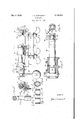
- FIG. 1 is a side elevation of a nut cracker constructed in accordance with my invention for 55 mounting on a table or like structure, the parts of the device being shown in the position they occupy when the movable jaw is retracted.
- Figure 2 is a larger sized plan View of the movable jaw structure with part of the shell ejector showing in the cut away portion in position when the nutcracker is used for nuts Whose outside shell diameter is such that they would press into the bore. It shows the adjusting head in section with the cracking pressure applying cam in position.
- Figure 3 is an end View of the movable jaw structure showing the oval concave cutting edge formed by. the removal of metal on two sides of the bore and on the other two sides on its outside surface, and also showing the shell ejector for same.
- Figure 4 is a sectional view taken on line A-A of Figure 1 looking in the direction of the arrow, the adjusting head and handle and part of the structure for securing to support not being shown.
- Figure 6 is. a section on the line B--B of Figure 5.
- Figure 7 is an end view of the die in the stationary jaw. showing the annular concave nut cutting edge formed on the end of the tubular piece.
- Figure 8 is a sectional view on line C-C of Figure '7 showing the removal of metal on two sides of itsouter surface to form part of its oval concave cutting edge.
- Figure 9 is a sectional View on line D-D of Figure;? showing removal of metal of its bore on the other two sides to form its oval annular concave cutting edge.
- 8 indicates generally the bodyof the device, the lower part having two lugstadaptedto secure same to a support and being provided with threaded studs l0 and the wing nuts l! with the plate i2 for attaching it to the corner of a table or other like support. Or it may be secured to a bench or rigid support by removing the plate l2 and using the studs I9 as bolts through the support.
- the body portion 8 is provided with a horizontal, laterally extending flange i3 which terminates at one end in an upwardly extending tubular support l5 which holds the die consisting of the stationary oval annular jaw of nut cutting member 32, the cutting edge of said member being symmetrically concave with relation to a chord connecting two points disposed 189 apart thereon, said chord being coincident with the long axis of the said cutting edge, as is most clearly shown in Figures 8 and 9.
- a tubular movable jaw operates at the other end of the arm l3 on the upper side thereof.
- a lug I! that constitutes a single thread nut for engagement with the thread on an adjusting head Ill.
- the movable jaw structure I4 is recessed on the end thereof that opposes jaw member 32 and has formed thereon an oval annular concave nut cutting edge.
- jaw structure 14 In the bore of jaw structure 14 shown by the dotted lines in Figures 1 and 2, operates a shell ejector [9, there being a slot 20 cut through the wall of the structure through which slot a stud 2
- a circumferential groove 22 Near the opposite end of the movable jaw structure I4 is a circumferential groove 22 into which a screw 23 protrudes to restrict the longitudinal movement of the jaw in relation to the adjustable head l8.
- a quick pitch thread At one end of the outside of the latter is formed a quick pitch thread which engages the nut I! on arm I3.
- a transverse bore On one end portion of the head l8, beyond the end of jaw structure l4 therein, is formed a transverse bore in which is mounted a cam 24.
- the combination head and cam restricts any retrograde movement of the movable jaw structure I4 when under pressure, and the cam 24 is so formed that angular movement of same on its own axis imparts cracking pressure to the movable jaw structure I4.
- a handle 25 is secured to the cam 24 by which the adjusting head is revolved to advance or retract the movable jaw structure [4, or to rotate the cam 24 after a nut has been clamped between the movable and stationary jaw.
- the side of the flange I3 is formed two projecting apertured lugs 26 in which is slideably mounted a shell ejector 21 that is associated with jaw 32, one end of ejector being threaded to receive two nuts 28 and 29.
- Nut 29 positioned on the opposite side of the rearmost lug 26 restricts the outward movement of the ejector and the nut 28 contacts the stud 2
- is threaded through support l5 and engages the ejector 21 for securing same in determined position so that a small pecan or the small end of a nut will not enter too far for eflicient cracking.
- the device is strong and durable and the operator may apply under complete control the force necessary to properly crack the nut with the least injury to the kernel in same.
- the cracker is also very efficient in cracking other than black walnuts.
- the cam is brought back to neutral position and the adjusting head is revolved in the reverse direction which retracts the movable jaw structure, releasing the nut and contacting the shell ejectors so that any shell forced into the bore of either jaw is ejected.
- a cracking jaw having an oval annular cutting edge that is concave with relation to a chord connecting two points disposed 180 apart therein, said chord being coincident with the long axis of the said cutting edge.
- a nut cracking device comprising a tubular nut-engaging element of circular cross section, the nut-engaging end of said element being exteriorly beveled at two diametrically opposite regions, and interiorly beveled at two diametrically opposite regions removed from said exteriorly beveled regions, to provide an annular, generally oval, nut-engaging edge.
- a nut cracker comprising a cracking jaw having a substantially annular non-planar cutting edge that is symmetrically concave at two diametrically opposite regions thereof.
Landscapes
- Life Sciences & Earth Sciences (AREA)
- Chemical & Material Sciences (AREA)
- Engineering & Computer Science (AREA)
- Food Science & Technology (AREA)
- Polymers & Plastics (AREA)
- Food-Manufacturing Devices (AREA)
Description
Dec. 6, 1938.
J. C. FIDDYMENT NUTCRACKER Filed Dec. 2]., 1935 1 N VEN TOR.
Patented Dec. 6, 1938 UNITED STATES PATENT OFFICE 3 Claims.
This invention relates to-nut crackers, and its chief object is to provide a nut cracker especially designed to crack black walnuts speedily and producea larger percentage of unbroken kernels and 5 totake care of thedifferent length and sizes of nuts with minimum effort.
The-invention consists of parts of special construction and arrangement whereby the nut holding heads or jaws have an oval annular cutting l edge concave on two sides, the lines of which conform asnearly as possible to the convex end of anaverage nut and will break theshell on both ends (to the outward side of the enclosed kernels and in such a manner that the side shell will 15:. inmost cases strip away from the kernel. The
centralinternal structure around which the kernels form is not necessarily broken down thus avoiding as much as possible the mutilation of same. The jaws can be separated or brought together on a nut quickly, and when the nut is clamped between the jaws the cracking pressure can be applied to just the degree that is necessary to crack the shell and not mutilate the kernel.
Theblack walnut is a hard nut to crack so that the kernel is exposed for easy removal and not mutilated. The shell formation and thickness is very irregular and most of the nuts have a strong internal. partition which divides the kernels in sections and which ofier much resistance to crushing when the effort is applied directly on the ends, and if so done, the breaking down of the internal partitions tends to crush the kernels more or less. With this device the center of the nutis forced intothe bore of the jaws the walls of. which contact with the exterior of the nut away from its central endand tend'to break the outer shell away from its internal structure withoutinecessarily breaking same. This affords a more favorable condition for removal of the kernels without being crushed.
This invention will be best understood from a consideration of the following detailed description taken in connection with the accompanying drawing forming part of this specification, it being understood that the invention is not confined to any strict conformity with the showing of the drawing, but may be changed or modified as long as such changes or modifications mark no material departure from the salient features of the invention as expressed in the appended claims.
In the drawing- Figure 1 is a side elevation of a nut cracker constructed in accordance with my invention for 55 mounting on a table or like structure, the parts of the device being shown in the position they occupy when the movable jaw is retracted.
Figure 2 is a larger sized plan View of the movable jaw structure with part of the shell ejector showing in the cut away portion in position when the nutcracker is used for nuts Whose outside shell diameter is such that they would press into the bore. It shows the adjusting head in section with the cracking pressure applying cam in position.
Figure 3 is an end View of the movable jaw structure showing the oval concave cutting edge formed by. the removal of metal on two sides of the bore and on the other two sides on its outside surface, and also showing the shell ejector for same.
Figure 4 is a sectional view taken on line A-A of Figure 1 looking in the direction of the arrow, the adjusting head and handle and part of the structure for securing to support not being shown.
Figure dis a side View of the nut cracking pressure applying cam.
Figure 6, is. a section on the line B--B of Figure 5.
Figure 7 is an end view of the die in the stationary jaw. showing the annular concave nut cutting edge formed on the end of the tubular piece.
Figure 8 is a sectional view on line C-C of Figure '7 showing the removal of metal on two sides of itsouter surface to form part of its oval concave cutting edge.
Figure 9 is a sectional View on line D-D of Figure;? showing removal of metal of its bore on the other two sides to form its oval annular concave cutting edge.
Referring tothedrawing, 8 indicates generally the bodyof the device, the lower part having two lugstadaptedto secure same to a support and being provided with threaded studs l0 and the wing nuts l! with the plate i2 for attaching it to the corner of a table or other like support. Or it may be secured to a bench or rigid support by removing the plate l2 and using the studs I9 as bolts through the support. The body portion 8 is provided with a horizontal, laterally extending flange i3 which terminates at one end in an upwardly extending tubular support l5 which holds the die consisting of the stationary oval annular jaw of nut cutting member 32, the cutting edge of said member being symmetrically concave with relation to a chord connecting two points disposed 189 apart thereon, said chord being coincident with the long axis of the said cutting edge, as is most clearly shown in Figures 8 and 9.
About midway between the ends of the arm I3 is another upwardly extending tubular support [6 in which a tubular movable jaw operates. At the other end of the arm l3 on the upper side thereof is cast a lug I! that constitutes a single thread nut for engagement with the thread on an adjusting head Ill. The movable jaw structure I4 is recessed on the end thereof that opposes jaw member 32 and has formed thereon an oval annular concave nut cutting edge.
In the bore of jaw structure 14 shown by the dotted lines in Figures 1 and 2, operates a shell ejector [9, there being a slot 20 cut through the wall of the structure through which slot a stud 2| operates, said stud being secured to the shell ejector I9. Near the opposite end of the movable jaw structure I4 is a circumferential groove 22 into which a screw 23 protrudes to restrict the longitudinal movement of the jaw in relation to the adjustable head l8. At one end of the outside of the latter is formed a quick pitch thread which engages the nut I! on arm I3. On one end portion of the head l8, beyond the end of jaw structure l4 therein, is formed a transverse bore in which is mounted a cam 24. The combination head and cam restricts any retrograde movement of the movable jaw structure I4 when under pressure, and the cam 24 is so formed that angular movement of same on its own axis imparts cracking pressure to the movable jaw structure I4. A handle 25 is secured to the cam 24 by which the adjusting head is revolved to advance or retract the movable jaw structure [4, or to rotate the cam 24 after a nut has been clamped between the movable and stationary jaw. 0n the side of the flange I3 is formed two projecting apertured lugs 26 in which is slideably mounted a shell ejector 21 that is associated with jaw 32, one end of ejector being threaded to receive two nuts 28 and 29. Nut 29 positioned on the opposite side of the rearmost lug 26 restricts the outward movement of the ejector and the nut 28 contacts the stud 2| in the movable structure 14 in arriving at the end of its outward position causing a movement of both shell ejectors to force out any shell that has broken off in either of the jaws.
30 is an opening cut through the wall of the movable jaw structure 14 on the opposite side to opening 20 into which the stud 2| can be inserted to limit the rearward movement of the shell ejector 19 when cracking small pecans or nuts that.
have a small shell diameter and thus prevent same from being forced further into the bore of the jaw. A set screw 3| is threaded through support l5 and engages the ejector 21 for securing same in determined position so that a small pecan or the small end of a nut will not enter too far for eflicient cracking. The device is strong and durable and the operator may apply under complete control the force necessary to properly crack the nut with the least injury to the kernel in same. The cracker is also very efficient in cracking other than black walnuts.
To crack a nut the same is positioned against the stationary jaw 32, the end of the nut being central to the jaw, and as most of the nuts are more or less convex on their ends they fit fairly well against the oval annular convex cutting edge of the jaws. The nut is tightly clamped between the two jaws by bringing the movable jaw structure forward by revolving the adjustable head. The cracking pressure is applied by a partial revolution of the cam which will cause the nut to crack along the lines of the annular oval concave cutting edge of the jaws. If the cam movement is not suflicient to crack the nut properly, the adjusting head is again revolved enough to take up the cam movement and the cam is given another partial revolution. After the nut has been cracked the cam is brought back to neutral position and the adjusting head is revolved in the reverse direction which retracts the movable jaw structure, releasing the nut and contacting the shell ejectors so that any shell forced into the bore of either jaw is ejected.
When cracking butter nuts, small sized pecans, etc. the outside shell diameter of which would not prevent them being pressed too far in the bore of the jaws, the stud 2| is turned further through the shell ejector I9 so that the end of the stud will come through same into the slot 30 which will limit its rearward movement and the set screw 3| is clamped against the stationary jaw shell ejector holding same in the position desired. In cracking Brazil nuts, the best results are obtained by applying the pressure directly on the ends of same which is done by having the shell ejectors as outlined above.
Having described the invention, I claim:
1. In a nut cracker, a cracking jaw having an oval annular cutting edge that is concave with relation to a chord connecting two points disposed 180 apart therein, said chord being coincident with the long axis of the said cutting edge.
2. A nut cracking device comprising a tubular nut-engaging element of circular cross section, the nut-engaging end of said element being exteriorly beveled at two diametrically opposite regions, and interiorly beveled at two diametrically opposite regions removed from said exteriorly beveled regions, to provide an annular, generally oval, nut-engaging edge.
3. A nut cracker comprising a cracking jaw having a substantially annular non-planar cutting edge that is symmetrically concave at two diametrically opposite regions thereof.
JOHN C. FIDDYMIENT.
Priority Applications (1)
| Application Number | Priority Date | Filing Date | Title |
|---|---|---|---|
| US55636A US2139264A (en) | 1935-12-21 | 1935-12-21 | Nutcracker |
Applications Claiming Priority (1)
| Application Number | Priority Date | Filing Date | Title |
|---|---|---|---|
| US55636A US2139264A (en) | 1935-12-21 | 1935-12-21 | Nutcracker |
Publications (1)
| Publication Number | Publication Date |
|---|---|
| US2139264A true US2139264A (en) | 1938-12-06 |
Family
ID=21999166
Family Applications (1)
| Application Number | Title | Priority Date | Filing Date |
|---|---|---|---|
| US55636A Expired - Lifetime US2139264A (en) | 1935-12-21 | 1935-12-21 | Nutcracker |
Country Status (1)
| Country | Link |
|---|---|
| US (1) | US2139264A (en) |
Cited By (1)
| Publication number | Priority date | Publication date | Assignee | Title |
|---|---|---|---|---|
| US2491559A (en) * | 1947-04-10 | 1949-12-20 | Hargretts Small Parts Machinin | Fixture |
-
1935
- 1935-12-21 US US55636A patent/US2139264A/en not_active Expired - Lifetime
Cited By (1)
| Publication number | Priority date | Publication date | Assignee | Title |
|---|---|---|---|---|
| US2491559A (en) * | 1947-04-10 | 1949-12-20 | Hargretts Small Parts Machinin | Fixture |
Similar Documents
| Publication | Publication Date | Title |
|---|---|---|
| US2488484A (en) | Pliers having insulated jaws and handles | |
| US2260708A (en) | Piston pin and king bolt vise | |
| US2058072A (en) | Nut recracker | |
| US2139264A (en) | Nutcracker | |
| US4145962A (en) | Nut cracker | |
| US4787307A (en) | Nutcracker | |
| US1552616A (en) | Battery-terminal puller | |
| US9138014B2 (en) | Apparatus for efficient nut cracking and method of using same | |
| US3223133A (en) | Nutcracker | |
| US1555518A (en) | Nutcracker | |
| US2218607A (en) | Method and means for cracking nuts | |
| US2378084A (en) | Nutcracker | |
| US1503635A (en) | Adjustable holder for gripping the ends of short rods | |
| US4079494A (en) | Single lever faucet cartridge extracting tool | |
| US2550197A (en) | Nutcracker automatically adjusted to crack nuts of various sizes | |
| US1548835A (en) | Device for removing broken wood screws | |
| US2396027A (en) | Bung | |
| US2989103A (en) | Nutcracker | |
| US1708147A (en) | Tappet wrench | |
| US1734270A (en) | Spark-plug wrench | |
| US3050102A (en) | Apparatus for spinning a lateral flange on a tube | |
| US2159593A (en) | Cylinder head puller | |
| US2482025A (en) | Nut breaking tool | |
| US2302323A (en) | Ice cream pie cutter | |
| US2558641A (en) | Tool for splitting metal nuts |