US2131069A - Manufacture of core elements - Google Patents
Manufacture of core elements Download PDFInfo
- Publication number
- US2131069A US2131069A US96194A US9619436A US2131069A US 2131069 A US2131069 A US 2131069A US 96194 A US96194 A US 96194A US 9619436 A US9619436 A US 9619436A US 2131069 A US2131069 A US 2131069A
- Authority
- US
- United States
- Prior art keywords
- loops
- rollers
- wires
- pair
- feeding
- Prior art date
- Legal status (The legal status is an assumption and is not a legal conclusion. Google has not performed a legal analysis and makes no representation as to the accuracy of the status listed.)
- Expired - Lifetime
Links
Images


Classifications
-
- E—FIXED CONSTRUCTIONS
- E06—DOORS, WINDOWS, SHUTTERS, OR ROLLER BLINDS IN GENERAL; LADDERS
- E06B—FIXED OR MOVABLE CLOSURES FOR OPENINGS IN BUILDINGS, VEHICLES, FENCES OR LIKE ENCLOSURES IN GENERAL, e.g. DOORS, WINDOWS, BLINDS, GATES
- E06B7/00—Special arrangements or measures in connection with doors or windows
- E06B7/16—Sealing arrangements on wings or parts co-operating with the wings
- E06B7/22—Sealing arrangements on wings or parts co-operating with the wings by means of elastic edgings, e.g. elastic rubber tubes; by means of resilient edgings, e.g. felt or plush strips, resilient metal strips
Definitions
- This invention relates to the manufacture of Figureis a side view with parts in section of elongated core members, more particularly for a weather strip embodying the invention; Weather strips, window channels and the like.
- the invention is illustrated and will be de-
- One of the objects of the invention is to proscribed in connection with the manufacture of 5- vide a method and machine for making a core a novel Weather Strip including an elongated member in which an elongated cordlike element d e e t e In of twisted p p is formed with a series of overlapping loops of rep Or the like having a P Of resilient Wires silient wire or the like extending. from one. side I and I2 wound therearound in the form of overthereof.
- the loops are formed by sepapp g l ps. th ps formed y the different arate wires wound about the cordlike element in Wires a er t ng along t length of h poverlapping relationship so that the loops mu- That p tion f e l ops a t hee me t tually brace and upport each other 10 has been compressed around the element as
- Various other objects of the invention relate indicated a and preferably Stretched beyond to the provision of a, simple and compact mathe elastic limit Of the wire S0 it Will not Spring chine for producing the core element automatiback and-the remainder of the 100115 has been 15 cally in which the wire loops are formed about a flattened to fo m fl op M n lying app o stationary pressure foot and the element and in mately in the S plane a One d O the e which the loops are subsequently flattened by ment'
- One machine for carrying out the invention September 7 includes an annular power rotated member
- the element I0 may be enclosed by a tubular carrying two wire spools and two feeding mech cover l5 of rubber or the like slit alonglone side anisms spaced 180 apart.
- a cordlike element to permit the-100193 to P oject t rough and a is fed through t neuter of t member by a fabric coverlB may enclose the entire assembly.
- The-cover'ls is Preferably Stitched wi l and y, foot is mounted in spaced relation to the element if desired, have other Seams therein W e it in such o iti t t t member t t projects outwardly ofthe element H), the covered the wires will be wound around the element and Projecting 100138 forming a resilient a taching presser foot in overlapping loops.
- the rollers flahge as fully described in y copending appli- 30 serve to draw the loops from the presser foot and h I to compress the loops about the element to secure The illustrated machine for forming the Weat them thereto.
- the core member f Strip comprises-a guide I810 e ve the e eis fed into a second set of rollers grooved to rement from a reel other suitable Source,
- Figure 1 is a plan View t parts Section f driven.
- the carriage 25 carries a pair of spools a, machine embodying the invention; l 29 carrying the wires I l and l2, which pass from Figure 2 is a section on th lin 11-41 -'of Figthe.
- the wires into overlapping loops larger than the element I 0.
- the wires will be tightly crimped around'the element due to the grooves 24 and will preferably be stretched beyond their elastic limit so-there will be little or no tendency to spring back.
- rollers '23'the core passes to a pair of rollers 45 and 4'! formed with registering grooves 48 to receive the element Ifland with substantially cylindrical portions 49 between which the loops l4 are flattened .-out.
- the roller 45 is mounted on a horizontal spindle on a rigid frame member 5
- hasanextension 55 which carries a screw 56 adapted to engage the end of the lever 54.
- the screw 56 serves as an adjustment to contr'olthe position of .theroller 4l thereby to adjust the pressure exerted on the element l0 and the loops I4 by thelrollersl lii and 41.
- the two sets of rollers 23 and 46. and 41 are preferably driven by the power, shaft'42 and for this purpose a suitable gear drive .51 is-provid'ed driving a shaft 58.
- the shaft 58 is'apreferably connected directly to one of rollers 23 which are geared together by pinions 59.
- the rollers 46 and 41 are preferably also geared together by pinions 5 I, one of which is geared to one of the pinions 59 by an idler pinion 62.
- a machine for-making'elongated core members comprising means for feeding a cordlike element of considerable length, a plurality of means evenly spaced about said element for applying a pluralityof wires to the element with portions encirclingthe element and portions projecting laterally fromthe element in overlapping loops arranged approximately in the same plane.
- a machine for making elongated core members comprising means for feeding a cordlike element of considerable length, a pair of means at diametrically opposite points about said element for applying a'pair of wires to the element with portions encircling the element and portions projecting laterally from the element in overlapping loops arranged approximately in the same plane.
- A'machinefor making elongated'core members comprising means for feeding a cordlike element of considerable length, a stationary presser foot spacedfrom and paralleling the element, means for winding a Wire around the element and the presser foot, and means for compressing the Wire'about the element with the portions thereof which encircled the presser foot projecting from the element in a series of loops.
- Amachine for making elongated core members comprising means for feeding a cordlike elementof considerable length, a stationary presser foot spaced from and paralleling the element, means for simultaneously winding a plurality of wires around the element andthe'presser foot, and means for compressing the wires about the element with the portions thereof which encircled thepresser foot projecting from the element in a series-of loops.
- a machine for making elongated core members comprising an annular rotary member carrying a supply of separate wires, means for feeding lengthwise through said member an elon- 'gated-cordlike.element,.means for winding said Wire's separately around said element in overlapping loops larger than the element, and means foricompressing said loops on the element.
- a machine for making'elongated core members comprising an annular rotary member car- 11.
- a machine for making elongated core members comprising an annular rotary member, a pair of spools forming supply sources for wires carried by said member, a pair of feeding mechanisms carried by said member at diametrically opposite points for feeding said wires, means for feeding lengthwise through said member an elongated cordlike element, said feeding mechanisms winding the wires around said element in a series of overlapping loops larger than the element as said member is rotated, and means for compressing said loops on the element.
- a machine for making elongated core members comprising an annular rotary member, a pair of spools forming supply sources for wires carried by said member, a pair of feeding mechanisms carried by said member at diametrically opposite points for feeding said wires, means for feeding lengthwise through said member an elongated cordlike element, a presser foot spaced from said element, said feeding mechanisms winding the wires around said element and presser foot in a series of overlapping loops larger than the element as said member is rotated, and means for compressing said loops on the element.
- a machine for making elongated core members comprising means for feeding a cordlike element lengthwise, means for winding a wire about said element in a series of loops larger than the element, and means for compressing the loops about said element with portions projecting in flat loops at one side thereof, said lastnamed means including a pair of rollers having registering grooves to receive said element and generally cylindrical portions to flatten said loops, and means for moving said rollers relatively toward and away from each other to adjust the pressure on the element and the wire.
- a machine for making elongated core members comprising means for feeding a cordlike element lengthwise, means for winding a wire about said element in a series of loops larger than the element, and means for compressing the loops about said element with portions projecting in flat loops at one side thereof, said lastnamed means including a pair of rollers having registering grooves to receive said element and generally cylindrical portions to flatten said loops, one of said rollers being mounted on a stationary part of the machine and the other roller being mounted on a movable part for movement toward and away from the first roller thereby to adjust the pressure on the element and the wire.
- a machine for making elongated core members comprising means for feeding a cordlike element lengthwise, means for winding a wire about said element in a series of loops larger the loops about said element with portions projecting in flat loops at one side thereof, said last-named means including a pair of rollers having registering grooves to receive said element and generally cylindrical. portions to flatten said loops, one of said rollers being mounted on a stationary part of the machine, a pivoted lever carrying the other roller for movement, toward and away from said one roller, and means for adjusting the position of said lever thereby to adjust the pressure on said element and wire.
- a machine for making elongated core members comprising means for feeding a'cordlike element lengthwise, means for winding a wire about said element in a series of loops larger than the element, and means for compressing the loops about said element with portions projecting in flat loops at one side thereof, said last-named means including a pair of rollers having registering grooves to receive said element and to compress the loops about said element, a second pair of rollers having registering grooves to receive said element and generally cylindrical portions to flatten said loops, one of said second pair of rollers being mounted on a fixed part and the other on a movable part whereby the pressure on the element and the loops can be adjusted.
- a machine for making elongated core than the element, and means for compressing members comprising means for supplying an elongated cordlike element, a pair of driven rollers having registering grooves to receive said element for feeding the element lengthwise, a presser foot rigidly secured to the machinespaced from and substantially paralleling said element, and means for winding a wire in loops about the element and presser foot, said rollers compressing said wire about the element and withdrawing the loops from the presser foot as the element is advanced.
- a machine for making elongated core members comprising means for supplying an elongated cordlike element, a pair of driven rollers having registering grooves to receive said element for feeding the element lengthwise, a presser foot rigidly secured to the machine spaced from and substantially paralleling said element, means for winding a wire in loops about the element and presser foot, said rollers compressing said wire about the element and withdrawing the loops from the presser foot as the element is advanced, a second pair of rollers having substantially cylindrical portions to flatten said loops, and means for adjusting said second pair of rollers thereby to adjust the pressure on the loops.
Description
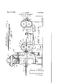
Sept. 27, 1938. R, c, P|E|E 2,131,069
MANUFACTURE OF CORE ELEMENTS Filed Aug. 15, 1936 3 Sheets-Sheet l I I gl INVENTOR. 2.? BYPO QT C. 95905 I me Cant =1- Bra-4%,
ATTORNEYS.
Sept. 27; 1938. C, ER E 2,131,069
MANUFACTURE OF CORE ELEMENTS Filed Aug. 15, 1 936 5 sheets -sheet 2 v INVENT OR. ROBERT C. PIERCE BY )7Zc 9 M ATTORN E Y5 Sept. 27, 1938. R. c. PIERCE MANUFACTURE OF GORE ELEMENTS Filed Aug. 15, 1936 3 Sheets-Sheet 3 INVENTOR. ROBERT C. P/EFPCE mc 7 13mm W ATTORNEYS.
Patented Sept. 27, 1938 r UNITED STATES PATENT OFFlCEb Y MANUFACTURE OF CORE, ELEMENTS Robert 0. Pierce,- Niles, Mich, assignorto National Standard Company, Niles, Mich a corporation of Michigan Application August 15, 1936, Serial No. 96,194
18 Claims. (Cl. 140-71) This invention relates to the manufacture of Figureis a side view with parts in section of elongated core members, more particularly for a weather strip embodying the invention; Weather strips, window channels and the like. The invention is illustrated and will be de- One of the objects of the invention is to proscribed in connection with the manufacture of 5- vide a method and machine for making a core a novel Weather Strip including an elongated member in which an elongated cordlike element d e e t e In of twisted p p is formed with a series of overlapping loops of rep Or the like having a P Of resilient Wires silient wire or the like extending. from one. side I and I2 wound therearound in the form of overthereof. Preferably the loops are formed by sepapp g l ps. th ps formed y the different arate wires wound about the cordlike element in Wires a er t ng along t length of h poverlapping relationship so that the loops mu- That p tion f e l ops a t hee me t tually brace and upport each other 10 has been compressed around the element as Various other objects of the invention relate indicated a and preferably Stretched beyond to the provision of a, simple and compact mathe elastic limit Of the wire S0 it Will not Spring chine for producing the core element automatiback and-the remainder of the 100115 has been 15 cally in which the wire loops are formed about a flattened to fo m fl op M n lying app o stationary pressure foot and the element and in mately in the S plane a One d O the e which the loops are subsequently flattened by ment' The core member v rs is more pa adjustable rollers whereby the flattening pressure ticulafly described and Claimed in y p can be t n ing divisional application SerialuNo. 162,44l,'filed 20 One machine for carrying out the invention September 7 includes an annular power rotated member The element I0 may be enclosed by a tubular carrying two wire spools and two feeding mech cover l5 of rubber or the like slit alonglone side anisms spaced 180 apart. A cordlike element to permit the-100193 to P oject t rough and a is fed through t neuter of t member by a fabric coverlB may enclose the entire assembly. 25 pair of grooved rollers and a stationary presser The-cover'ls is Preferably Stitched wi l and y, foot is mounted in spaced relation to the element if desired, have other Seams therein W e it in such o iti t t t member t t projects outwardly ofthe element H), the covered the wires will be wound around the element and Projecting 100138 forming a resilient a taching presser foot in overlapping loops. The rollers flahge as fully described in y copending appli- 30 serve to draw the loops from the presser foot and h I to compress the loops about the element to secure The illustrated machine for forming the Weat them thereto. From the rollers the core member f Strip comprises-a guide I810 e ve the e eis fed into a second set of rollers grooved to rement from a reel other suitable Source,
5 ceive the element and having substantially cylinnot Shown- From the guide the element as drioal portions t flatten t 100p Preferably over a suitable tensioning shoe l9 pivoted on a n of t second t of rollers is mounted on horizontal lever 2| which isurged by an adjusta rigid part of the machine and-the other on an able Spring 22 in a direction o p t e element adjustable lever so that the pressure exerted frictional'ly against e "guide 8 to maintain thereby on th loops and t 1 1; can be suitable tension thereon. A pair of power driven 40 j st rollers 23 formed with registering grooves 24 'I'he above and other objects and novel features to receive the element 10 draw it lengthwise under of the invention including desirable sub-combinatension from he Shoe l9. tions and particular arrangements of parts will The u de 8 is at the-center of an annular be apparent from the following description when Carriage rotatably' 011 l1ed-0n bearings 2'6 45 read in connection with the accompanying drawon 'atp r of spaced pp and Which is.
ings in which; formed-with a sprocket gear-28-by which it isv Figure 1 is a plan View t parts Section f driven. The carriage 25 carries a pair of spools a, machine embodying the invention; l 29 carrying the wires I l and l2, which pass from Figure 2 is a section on th lin 11-41 -'of Figthe. spools through suitable guide members '3I 50 ure 1; (Figure:2-)fand then one or more times around Figure 3 is a section on the line III-III of Fi'gtensioning rollers 32 which are arranged at diaure 2; metrically-oppositepoints and guide the wires as Figure 4 is a partial section on the line IV--IV they are wound around the element). The tenof Figure 1; and V 7 sioning rollers are held by frictionshoes 33 55 I journaled in a frame 43. The shaft 42 may be driven by a pulley wheel 44 belted to any suit able source of power. As the carriage 25 rotates, the wires II and 12 will be wound around the element 1 0 and around a suitable presser foot .45 whichis rigidly secured to the machine frame spaced from but substantially parallel to the element ID;
the wires into overlapping loops larger than the element I 0. As the element ID with thewires H and I2 looped around it passesthrough the rollers 23, the wires will be tightly crimped around'the element due to the grooves 24 and will preferably be stretched beyond their elastic limit so-there will be little or no tendency to spring back.
From the rollers '23'the core. passes to a pair of rollers 45 and 4'! formed with registering grooves 48 to receive the element Ifland with substantially cylindrical portions 49 between which the loops l4 are flattened .-out. The roller 45 is mounted on a horizontal spindle on a rigid frame member 5| and the roller 41' is mounted on a lever52 which is pivoted at oneend' on the frame! and has its otherend connected by a link- 53 to a lever 54 likewise pivoted on theframe 5 I. The frame 5| hasanextension 55 which carries a screw 56 adapted to engage the end of the lever 54. As will be apparent the screw 56 serves as an adjustment to contr'olthe position of .theroller 4l thereby to adjust the pressure exerted on the element l0 and the loops I4 by thelrollersl lii and 41. The two sets of rollers 23 and 46. and 41 are preferably driven by the power, shaft'42 and for this purpose a suitable gear drive .51 is-provid'ed driving a shaft 58. The shaft 58 is'apreferably connected directly to one of rollers 23 which are geared together by pinions 59. 3 The rollers 46 and 41 are preferably also geared together by pinions 5 I, one of which is geared to one of the pinions 59 by an idler pinion 62. In this way the speeds of all of the various elements are synchronizedso that the loops M will always be evenly spaced on the element l0 and there will be no tendency to break the element l0. While one embodiment'of the invention hasbeen illustrated and described in detail, it is-not to be understood that the scope of the invention is limited to that particular embodiment, or other.- wise than by the terms of the appended claims. I
What is claimed is:
1. The method of making elongated core' memelement and a'presserfoot spaced from-the'ele-' ment in evenly-spaced overlapping lgopsllarger than the diameter of the element, compressing The presser foot 45 extends past the rollers 23 and serves, to form,
flattened loops at one side only of the element.
4; Themethod of making elongated core members which comprises feeding a cordlike element lengthwise, winding a pair of wires around the [element and a presser foot spaced therefrom at diametrically-opposite points to form evenlyspaced overlapping loops larger than the element, compressing said loops about the element leaving the excess wire projecting in flattened loops at one side only of, the element and withdrawing the loopsfrom the presser foot. 7
5 A machine for-making'elongated core members comprising means for feeding a cordlike element of considerable length, a plurality of means evenly spaced about said element for applying a pluralityof wires to the element with portions encirclingthe element and portions projecting laterally fromthe element in overlapping loops arranged approximately in the same plane.
v6. A machine for making elongated core members comprising means for feeding a cordlike element of considerable length, a pair of means at diametrically opposite points about said element for applying a'pair of wires to the element with portions encircling the element and portions projecting laterally from the element in overlapping loops arranged approximately in the same plane.
7. A'machinefor making elongated'core members comprising means for feeding a cordlike element of considerable length, a stationary presser foot spacedfrom and paralleling the element, means for winding a Wire around the element and the presser foot, and means for compressing the Wire'about the element with the portions thereof which encircled the presser foot projecting from the element in a series of loops. 8. Amachine for making elongated core members comprising means for feeding a cordlike elementof considerable length, a stationary presser foot spaced from and paralleling the element, means for simultaneously winding a plurality of wires around the element andthe'presser foot, and means for compressing the wires about the element with the portions thereof which encircled thepresser foot projecting from the element in a series-of loops.
9. A machine for making elongated core members comprising an annular rotary member carrying a supply of separate wires, means for feeding lengthwise through said member an elon- 'gated-cordlike.element,.means for winding said Wire's separately around said element in overlapping loops larger than the element, and means foricompressing said loops on the element.
-10. A machine for making'elongated core members comprising an annular rotary member car- 11. A machine for making elongated core members comprising an annular rotary member, a pair of spools forming supply sources for wires carried by said member, a pair of feeding mechanisms carried by said member at diametrically opposite points for feeding said wires, means for feeding lengthwise through said member an elongated cordlike element, said feeding mechanisms winding the wires around said element in a series of overlapping loops larger than the element as said member is rotated, and means for compressing said loops on the element.
12. A machine for making elongated core members comprising an annular rotary member, a pair of spools forming supply sources for wires carried by said member, a pair of feeding mechanisms carried by said member at diametrically opposite points for feeding said wires, means for feeding lengthwise through said member an elongated cordlike element, a presser foot spaced from said element, said feeding mechanisms winding the wires around said element and presser foot in a series of overlapping loops larger than the element as said member is rotated, and means for compressing said loops on the element.
13. A machine for making elongated core members comprising means for feeding a cordlike element lengthwise, means for winding a wire about said element in a series of loops larger than the element, and means for compressing the loops about said element with portions projecting in flat loops at one side thereof, said lastnamed means including a pair of rollers having registering grooves to receive said element and generally cylindrical portions to flatten said loops, and means for moving said rollers relatively toward and away from each other to adjust the pressure on the element and the wire.
14. A machine for making elongated core members comprising means for feeding a cordlike element lengthwise, means for winding a wire about said element in a series of loops larger than the element, and means for compressing the loops about said element with portions projecting in flat loops at one side thereof, said lastnamed means including a pair of rollers having registering grooves to receive said element and generally cylindrical portions to flatten said loops, one of said rollers being mounted on a stationary part of the machine and the other roller being mounted on a movable part for movement toward and away from the first roller thereby to adjust the pressure on the element and the wire.
15. A machine for making elongated core members comprising means for feeding a cordlike element lengthwise, means for winding a wire about said element in a series of loops larger the loops about said element with portions projecting in flat loops at one side thereof, said last-named means including a pair of rollers having registering grooves to receive said element and generally cylindrical. portions to flatten said loops, one of said rollers being mounted on a stationary part of the machine, a pivoted lever carrying the other roller for movement, toward and away from said one roller, and means for adjusting the position of said lever thereby to adjust the pressure on said element and wire.
16. A machine for making elongated core members comprising means for feeding a'cordlike element lengthwise, means for winding a wire about said element in a series of loops larger than the element, and means for compressing the loops about said element with portions projecting in flat loops at one side thereof, said last-named means including a pair of rollers having registering grooves to receive said element and to compress the loops about said element, a second pair of rollers having registering grooves to receive said element and generally cylindrical portions to flatten said loops, one of said second pair of rollers being mounted on a fixed part and the other on a movable part whereby the pressure on the element and the loops can be adjusted.
17. A machine for making elongated core than the element, and means for compressing members comprising means for supplying an elongated cordlike element, a pair of driven rollers having registering grooves to receive said element for feeding the element lengthwise, a presser foot rigidly secured to the machinespaced from and substantially paralleling said element, and means for winding a wire in loops about the element and presser foot, said rollers compressing said wire about the element and withdrawing the loops from the presser foot as the element is advanced.
18. A machine for making elongated core members comprising means for supplying an elongated cordlike element, a pair of driven rollers having registering grooves to receive said element for feeding the element lengthwise, a presser foot rigidly secured to the machine spaced from and substantially paralleling said element, means for winding a wire in loops about the element and presser foot, said rollers compressing said wire about the element and withdrawing the loops from the presser foot as the element is advanced, a second pair of rollers having substantially cylindrical portions to flatten said loops, and means for adjusting said second pair of rollers thereby to adjust the pressure on the loops. 1 34 S l ROBERT C. PIERCE.
Priority Applications (2)
| Application Number | Priority Date | Filing Date | Title |
|---|---|---|---|
| US96194A US2131069A (en) | 1936-08-15 | 1936-08-15 | Manufacture of core elements |
| US162441A US2156164A (en) | 1936-08-15 | 1937-09-04 | Core member |
Applications Claiming Priority (1)
| Application Number | Priority Date | Filing Date | Title |
|---|---|---|---|
| US96194A US2131069A (en) | 1936-08-15 | 1936-08-15 | Manufacture of core elements |
Publications (1)
| Publication Number | Publication Date |
|---|---|
| US2131069A true US2131069A (en) | 1938-09-27 |
Family
ID=22256247
Family Applications (1)
| Application Number | Title | Priority Date | Filing Date |
|---|---|---|---|
| US96194A Expired - Lifetime US2131069A (en) | 1936-08-15 | 1936-08-15 | Manufacture of core elements |
Country Status (1)
| Country | Link |
|---|---|
| US (1) | US2131069A (en) |
Cited By (1)
| Publication number | Priority date | Publication date | Assignee | Title |
|---|---|---|---|---|
| US3037343A (en) * | 1957-04-11 | 1962-06-05 | Goodrich Co B F | Method and apparatus for manufacturing hose |
-
1936
- 1936-08-15 US US96194A patent/US2131069A/en not_active Expired - Lifetime
Cited By (1)
| Publication number | Priority date | Publication date | Assignee | Title |
|---|---|---|---|---|
| US3037343A (en) * | 1957-04-11 | 1962-06-05 | Goodrich Co B F | Method and apparatus for manufacturing hose |
Similar Documents
| Publication | Publication Date | Title |
|---|---|---|
| US2702067A (en) | Machine for making covered apparel belts | |
| US2681019A (en) | Method of and apparatus for manufacturing bielastic tapes | |
| US2131069A (en) | Manufacture of core elements | |
| US2137697A (en) | Manufacture of weather-strip elements | |
| US2281308A (en) | Mechanism for the manufacture of comfortables, quilts, and the like | |
| US2761488A (en) | Apparatus for applying camel back to a tire casing | |
| US2335219A (en) | Apparatus for making ornamental material | |
| US3152433A (en) | Method and apparatus for making plastic filament coils for zipper fasteners | |
| IE34858B1 (en) | A machine for producing continuous coiled filaments for slide fastener stringers | |
| US2430463A (en) | Strip edge infolding machine | |
| US1500984A (en) | Wrapping machine | |
| US2324668A (en) | Machine for making twisted paper | |
| US1415313A (en) | Method of making leather yarn and article | |
| US1608193A (en) | Winding and reeling mechanism | |
| US3903819A (en) | Ribbon charging apparatus | |
| US2406033A (en) | Apparatus for the manufacture of convoluted rods | |
| US1499924A (en) | Machine for cutting tubular stock into continuous strips | |
| US1505425A (en) | Cutting machine | |
| US2108664A (en) | Apparatus for winding material | |
| US2690784A (en) | Strip applying device | |
| US2551851A (en) | Electronic seaming machine | |
| US1734018A (en) | Method and apparatus for making bead material | |
| US2252465A (en) | Rope twisting and laying machine | |
| US2155186A (en) | Machinery for making wire fencing | |
| US1759643A (en) | Method of forming back heel seams for footwear |