US2123742A - Air conditioning - Google Patents
Air conditioning Download PDFInfo
- Publication number
- US2123742A US2123742A US500716A US50071630A US2123742A US 2123742 A US2123742 A US 2123742A US 500716 A US500716 A US 500716A US 50071630 A US50071630 A US 50071630A US 2123742 A US2123742 A US 2123742A
- Authority
- US
- United States
- Prior art keywords
- air
- temperature
- thermostat
- water
- casing
- Prior art date
- Legal status (The legal status is an assumption and is not a legal conclusion. Google has not performed a legal analysis and makes no representation as to the accuracy of the status listed.)
- Expired - Lifetime
Links
- 238000004378 air conditioning Methods 0.000 title description 13
- XLYOFNOQVPJJNP-UHFFFAOYSA-N water Substances O XLYOFNOQVPJJNP-UHFFFAOYSA-N 0.000 description 45
- 239000007921 spray Substances 0.000 description 27
- 238000001816 cooling Methods 0.000 description 24
- 230000001143 conditioned effect Effects 0.000 description 10
- 239000007788 liquid Substances 0.000 description 10
- 230000001276 controlling effect Effects 0.000 description 9
- 238000005507 spraying Methods 0.000 description 8
- 239000002245 particle Substances 0.000 description 7
- 239000002826 coolant Substances 0.000 description 6
- 230000001105 regulatory effect Effects 0.000 description 6
- 230000003750 conditioning effect Effects 0.000 description 5
- 230000009471 action Effects 0.000 description 4
- 230000000694 effects Effects 0.000 description 4
- 238000000034 method Methods 0.000 description 4
- 230000008859 change Effects 0.000 description 3
- 230000005494 condensation Effects 0.000 description 3
- 238000009833 condensation Methods 0.000 description 3
- 238000007791 dehumidification Methods 0.000 description 3
- 229920006395 saturated elastomer Polymers 0.000 description 3
- 238000004140 cleaning Methods 0.000 description 2
- 229940000425 combination drug Drugs 0.000 description 2
- 238000013459 approach Methods 0.000 description 1
- 230000009977 dual effect Effects 0.000 description 1
- 239000000428 dust Substances 0.000 description 1
- 239000012535 impurity Substances 0.000 description 1
- 238000009434 installation Methods 0.000 description 1
- 230000007246 mechanism Effects 0.000 description 1
- 230000009467 reduction Effects 0.000 description 1
- 230000000717 retained effect Effects 0.000 description 1
Images
Classifications
-
- F—MECHANICAL ENGINEERING; LIGHTING; HEATING; WEAPONS; BLASTING
- F24—HEATING; RANGES; VENTILATING
- F24F—AIR-CONDITIONING; AIR-HUMIDIFICATION; VENTILATION; USE OF AIR CURRENTS FOR SCREENING
- F24F5/00—Air-conditioning systems or apparatus not covered by F24F1/00 or F24F3/00, e.g. using solar heat or combined with household units such as an oven or water heater
- F24F5/0007—Air-conditioning systems or apparatus not covered by F24F1/00 or F24F3/00, e.g. using solar heat or combined with household units such as an oven or water heater cooling apparatus specially adapted for use in air-conditioning
-
- F—MECHANICAL ENGINEERING; LIGHTING; HEATING; WEAPONS; BLASTING
- F24—HEATING; RANGES; VENTILATING
- F24F—AIR-CONDITIONING; AIR-HUMIDIFICATION; VENTILATION; USE OF AIR CURRENTS FOR SCREENING
- F24F6/00—Air-humidification, e.g. cooling by humidification
- F24F6/12—Air-humidification, e.g. cooling by humidification by forming water dispersions in the air
- F24F6/14—Air-humidification, e.g. cooling by humidification by forming water dispersions in the air using nozzles
- F24F2006/146—Air-humidification, e.g. cooling by humidification by forming water dispersions in the air using nozzles using pressurised water for spraying
Definitions
- This invention relates to improvements in air conditioning, and more particularly to apparatus for controlling the temperature conditions of air delivered into auditoriums, theatres, and special 5 purpose rooms in industrial plants.
- the object of the invention is to provide a practical and efiiclent method of regulating the temperature of theconditioned air by the temperature in the room or auditorium by controlling the volume of water utilized, in the conditioning apparatus for cooling the air, by thermostatic means located in the conditioned room or auditorium.
- a further object of the invention is to provide a dual control whereby both temperature and humidity conditions are maintained to afford the desired conditions of comfort.
- the conditioning apparatus consists in general of a chamber or housing I, having air inlet openings or ducts 2 and 3 communicating at one end, and leading to a fan chambertat its other end through an inter- 5 mediate converging section 5.
- a fan 6 of asuitable suction type, driven by a motor "I and operative to draw the air through the casing l and discharge it through an outlet duct 8 into the auditorium through 10 smaller ducts and passages.
- the air entering the casing I through the openings or passages 2 and 3 is admitted from two sources, viz., from the outer atmosphere and from the interior of the auditorium.
- the 15 passage 2 is the fresh air inlet and the passage 3 the return or recirculated air inlet, the fresh air being at the outside temperature and the return air at the inside temperature, and which vary according to the climate and season of the year.
- 20 Sets of dampers 9 and It are located in these fresh air and return air passages respectively, and these are thermostatically operated to regulate the proportion of each source of air, as will later be described in detail.
- a dehumidifier may be any cooling surface or medium into which the 30 incoming air comes into contact, so that 'a cooling effect is produced.
- a water spray or refrigerated coils may serve as a dehumidifier, although I prefer to employ a combination of the two, and control the degree of dehumidifying v and consequently the temperature by regulating automatically the amount of water issuing from the spray heads.
- the central portion of the casing i are three vertical banks of refrigerranged in' pairs, one pair to acoil, each pair 5 being connected together, exterior to one side of the casing and with a branch'supply pipe l3,
- each of the branch supply pipes I 3 is a valve it of the diaphragm or other suitable type, the same being operated by bellows units ll, as will hereafter be described.
- a branch supply pipe 20 leads from the main supply pipe l4, and located in this branch pipe is a threeway valve 2
- enters the casing and empties into a shallow receptacle or pan 24 in the bottom of the casing and extending beneath the area within the range of the spray heads.
- This receptacle collects the water discharged from the several sets of spray heads, and the water therein is recirculated through a return pipe 25 leading from the receptacle to the suction side of the pump l5.
- the air cleaning element consisting of a vertical bank 26 of zig-zag plates spaced at short distances apart and. thus forming a multiplicity of circuitous passages through which the air is drawn.
- the surface of this bank of plates is continually sprayed with water which is supplied through a header 21 extending across the upper portion of the casing, and provided with a series of nozzles 2
- This header is also supplied with water from the pump through a branch pipe 28 from the main supply pipe H.
- the function of the air-cleaning element is to remove the impurities from the air, suchas particles of dust and dirt which impinge against the wet surface of the zig-zag plates and are retained and eventually washed down into the receptacle below.
- the air cleaner is not essentially a part of the dehumidifying. apparatus, and therefore functions continuously and steadily while the systein is in operation.
- valves l5 and l1 and 22 the same being of any suitable type and design operating by variations of air pressure to open and close the valves.
- the air pressure to these bellows units is supplied through an arrangement of piping connected with a suitable compressor unit whereby a pressure of, say 15 pounds is maintained.
- a main air supply pipe is connected in parallel with all of the bellows units l1 and 22 through short branch pipes 30', so that all of them operate in unison to increase or decrease the supply of water admitted through their respective valves to the several spray heads.
- the air pressure in the pipe 30 leading to the pressure-controlled valves is thermostatically controlled by the following arrangement of thermostats and connecting air pipes: Since it is the purpose to regulate the temperature of the air primarily by that in the auditorium, a thermostat 3
- thermostat 33 Adjacent the thermostat 33 is another thermostat 34 having a temperature-responsive element which is the equivalent of a dry bulb thermometer and thus registers the actual temperature, whereas the heat-responsive element of the thermostat 33 is the equivalent of a wet bulb thermometer which registers a slightly lower temperature, depending on the relative humidity of the air. Thus between the wet and dry bulb temperatures there is a diiferential of charged will have a certain relative humidity predetermined as conducive to maximum comfort in the room being supplied.
- the wet bulb thermostat 33 directly controls the air pressure in pipe 30 leading to the bellows-actuatedvalves ll in the water supply pipes l3, while the thermostat 3
- the wet bulb thermostat 33 may be considered as consisting of a bellows or other pneumatically-expansible unit which is operatively connected with a valve controlling the air pressure admitted to the pipe 30 through an air supply pipe 35, the bellows being so arranged as to admit air to regulate the valves
- the wet bulb thermostat 33 is in immediate control of the valves to the water sprays, but its operation is controlled by the other two thermostats acting together or singly, depending on the difference in the temperature of the air in the auditorium and that being supplied thereto.
- the cooling of the air also results in a reduction of the moisture content as a portion is condensed, so that as the air leaves the dehumidifier it is at a lower temperature and has a lower moisture content than when it entered.
- the air will be cooled whenever the temperature of the water cooling medium is lower than that of the air, while the amount of cooling, i. e., the heat extracted from the air will be proportional to the area of the cooling medium available for contact with the air, which in the present disclosure is represented by the volume of water that is being sprayed into the chamber at any given moment.
- Dehumidification on the other hand is the removal of moisture from the air by condensation, and involves the cooling of the air below its saturation temperature.
- the air may be treated without altering its temperature or its relative humidity, or it can be reduced to a saturation point of any predetermined temperature, and further can be conditioned and delivered in any desired relationship between the dry bulb, the wet bulb and saturation temperatures, by the setting of the several thermostatic devices, so that theair on being discharged into the room will, when mixed with the air already in the room, produce the desired degree of comfort.
- This increase would actuate the dry bulb thermostat so as to admit air pressure through the pipe 35 to the wet bulb thermostat and thus increase the temperature setting thereof to 158, or 3 higher than normal, in order to maintain the same difierential and therefore the same relative humidity in the air discharged into the room.
- the wet bulb thermostat would not function to vary the volume of spray water until the wet bulb temperature reached 68 instead of 65. But the air at 73 is too high to maintain the room at a normal temperature of 75, so con sequently the temperature of the return air would be increased and the thermostat 3
- the three thermostats counteract each others action in such a way as to maintain a balanced condition of temperature and relative humidity in the system at all times, this being accomplished entirely by regulating the amount of water spray and consequently the cooling effect on the air.
- thermostat 3! is the instrument in primary control of the system, since it responds to temperature changes in the auditorium, and in so doing governs the setting of wet bulb thermostat 33- which in turn directly controls the water supply to the spray head in the dehumidifying chamber. .Thus, for example, assuming a condition of 50% occupancy of the auditorium at a temperature of 75, a further increase in occupancy would be accompanied with an increase in temperature due to greater bodily heat given off. Now, thermostat 3!
- thermostat 34 is set at 70 as in the example given, an increase in the wet bulb temperature to 68 means a lesser differential, and consequently a more humid condition of the air, for the less the differential the more nearly the air approaches a saturated condition.
- the dry bulb thermostats automatically correct this condition by passing air from pipe 35 and through pipe 36 connected with pipe 32 leading from thermostat 3
- the purpose of the wet and dry bulb thermostats 33 and 34 essentially act as a check on the thermostat 3i to insure against the delivery of saturated air into the auditorium.
- the percentage of moisture in the air is not an important factor, and therefore the wet and dry bulb thermostats may be omitted and the volume of water spray controlled entirely by the .thermostat 3
- would be connected directly with the pipe and thus control the operation of the spray water valves I6 direct.
- thermostats control air-actuated bellows units 39 and 40, connected with the dampers in their respective air passages, and are set to function throughout a given range of, temperature.
- the thermostatically-controlled unit 39 closes the damper 9 in the fresh air intake passage and the unit 40 opens the damper 10 in the return air passage, so that a greater proportion of the warm inside air to cold outside air enters the dehumidifier.
- This part of the apparatus iscommonly used and therefore is disclosed only for the purpose of showing the complete system.
- an air conditioning apparatus the combination of a casing through which the air to be conditioned is circulated, cooling coils mounted in said casing, means for spraying water including a supply pipe, a pressure-actuated valve in said supply pipe, a thermostat responsive to the temperature in the room to which the conditioned air is delivered, and a thermostat responsive to the wet bulb temperature of air discharged from said casing, said thermostats being inter-connected to regulate said water supply valve and thereby control the temperature and relative humidity of the discharged air according to the temperature conditions in the room.
- a casing through which the air to be conditioned is circulated cooling coils mounted in said casing, means for spraying water including a supply pipe, a pressure-actuated valve in said supply pipe, a pair of thermostats located in the delivery end of the casing, one responsive to the wet bulb temperature and the other to the. dry bulb temperature of the air delivered to the room being supplied, and a thermostat responsive to the temperature in said room, said thermostats acting in conjunction to control the volume of spray water and thereby the relative humidity and temperature of the air delivered to said room.
- a casing through which the air to be conditioned is circulated cooling coils mounted in said casing, a circulating spray water system, and means for automatically controlling the volume of water sprayed, comprising a pressure-actuated valve in said supply pipe, a pair of thermostats located in the delivery end of the casing, one responsive to the wet bulb temperature and the other to the dry bulb temperature of the air delivered to the room being supplied, and a thermostat responsive to the temperature in said room,
- said wet bulb thermostat directly controlling said water supply valve and said dry bulb thermostat and room thermostat acting indirectly to control the setting of said wet bulb thermostat, whereby the air is delivered to the room at a constant relative humidity and at the temperature determined by said room thermostat.
- the combi-' nation-of a casing through which air to be conditioned is circulated, cooling coils mounted in said casing, means for spraying water including a supply pipe having a valve therein, pneumatic valve-actuating means including an air supply line, a thermostat located in the delivery end of said casing for controlling the air pressure in said .air line and responsive to the wet bulb temperature of the air, a thermostat located adjacent said wet bulb thermostat and responsive to the dry bulb temperature of the air, said thermostats being normally set to a predetermined temperature differential corresponding to a desired relative humidity, said dry bulb thermostat being connected by an auxiliary air pressure line to said wet bulb thermostat and operative to increase or decrease the setting thereof with corresponding changes in the dry bulb temperature, and a thermostat in the room and also connected with said wet bulb thermostat by an auxiliaryair pressure line and operative to indirectly control the setting thereof by the temperature in the room.
- air cooling means within said casing including a water spraying device and water supply pipe, a pressure actuated valve in said supply pipe, a temperature responsiv'e device on the inlet side of said casing and co-acting wet and dry temperature responsive devices on the discharge side of said casing, said devices being interconnected to control the volume of water delivered to said'spraying device.
- an air conditioning apparatus the com bination of a casing through which air to be conditioned is circulated, air cooling devices in said casing comprising cooling coils and water spraying elements, a water supply pipe connected with said spraying elements, a valve in said supply pipe, pressure-regulated means for operating said valve including interconnected thermostatically actuated devices responsive to the condition of the air entering and leaving said casing, and operating to control the temperature and 'relative humidity of the air by the volume of water sprayed over said coils.
- a method of conditioning air consisting of passing all of the air to be conditioned through a chamber in which a cooling medium is located and controlling the temperature and/or relative humidity of the air by varying the area of said cooling medium exposed to contact with the air through the medium of inter-connected thermostats responsive to the temperature of the air' before entering, and the wet and dry bulb temperatures of the air after leaving said chamber.
- the method of cooling and dehumidifying a quantity of air which comprises moving the air through an unobstructed passageway, subjecting the entire volume of air in such stream to the action of a cooling medium in the form of segregated liquid particles in such manner that some of the air in the streamvis cooled to a temperature below its dew point and moisture is condensed therefrom while other portions of said air are cooled to a lesser extent, the total cooling eflect being insufficient to bring the average air stream temperature down to the saturation value, and varying the degree of dehumidification obtained by varying the surface area of said segregated liquid particles while in heat-exchanging relation with said air stream.
- the method of cooling and dehumidifying a quantity of air' which comprises propelling the air in a single stream through an unobstructed passageway, projecting a liquid at a temperature below the dew point of the air stream across said air stream in the form of a curtain of segregated liquid particles in such manner as to cool a portion of the air in such stream to a temperature below its dew point while cooling other portions of said air to a temperature above its dew point whereby heat is extracted from portions of said air as latent heat of condensation and from other portions of said air as sensible heat and varying the quantity of heat extracted as latent heat of condensation by adjusting said sprays to alter the surface area of the liquid particles in heat-exchanging relation with said air stream.
- the combi nation with the enclosure in which conditioned air is used, of a conduit of undivided cross section, means for propelling a single stream of air co-extensive with said conduit through said conduit into said enclosure, aseries of liquid sprays extending across the top of said conduit, means for supplying said sprays with liquid at a temperature below the dew point of the air in said stream, said sprays being designed to discharge the liquid therefrom in streams of liquid particles, and means for adjusting said sprays to vary the surface area of the liquid particles in heat-exchanging relation with the air in said stream to thereby vary the proportion of the air whose temperature is reduced below its dew point.
Landscapes
- Engineering & Computer Science (AREA)
- Life Sciences & Earth Sciences (AREA)
- Sustainable Development (AREA)
- Chemical & Material Sciences (AREA)
- Combustion & Propulsion (AREA)
- Mechanical Engineering (AREA)
- General Engineering & Computer Science (AREA)
- Central Air Conditioning (AREA)
Description
July 12 1938. B. OFFEN 2,123,742
AIR CONDITIONING Fi'led Dec, 8, 1950 2 Sheets-Shet 1 July 12, 1938. B. OFFEN 9 AIR CONDITIONING Filed Dec. 8, 1950 2 Sheets-Sheet 2 Patented July 12, 1938 I UNITED srATas AIR ooum'rromno Bernard Oii'en, Chicago, Ill., assignor, by mesne assignments, to Carrler Corporation, Newark, N. J-., a corporation of Delaware Application December 8 ,1930, Serial No. 500,716
11 Glalms. (Cl. 261-115) Y This invention relates to improvements in air conditioning, and more particularly to apparatus for controlling the temperature conditions of air delivered into auditoriums, theatres, and special 5 purpose rooms in industrial plants.
The object of the invention is to provide a practical and efiiclent method of regulating the temperature of theconditioned air by the temperature in the room or auditorium by controlling the volume of water utilized, in the conditioning apparatus for cooling the air, by thermostatic means located in the conditioned room or auditorium.
In addition to the temperature, the humidity of the air is a factor in the conditioning of air and therefore a further object of the invention is to provide a dual control whereby both temperature and humidity conditions are maintained to afford the desired conditions of comfort.
' As well knownv in the art of air conditionin the amount of moisture in the air, expressed in terms of relative humidity, has a marked effect on the temperature to which the air may be heated to give the proper conditions of bodily g5 comfort. Thus air containing a high percentage of moisture can be supplied at a lower temperature and vice versa, so that the properconditioning of air is a matter of maintaining a certain differential between the temperature and humidity, as for instance as recorded by wet or dry bulb thermometers. This differential, however, is not constant but variable with the changes 'in the atmospheric conditions in the auditorium or other space being supplied. For example, a
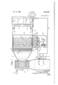
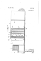
crowded auditorium in cold weather demands a different conditioning, of the air supply than during warm or mild weather, or when partially filled, so that regardless of exterior conditions and temperature, any automatic control of air conditioning system should properly be governed by the temperature within the space to which air is delivered. Thus the present disclosure depends not so muchon the units which make up the I Referring to Figure 1, the conditioning apparatus consists in general of a chamber or housing I, having air inlet openings or ducts 2 and 3 communicating at one end, and leading to a fan chambertat its other end through an inter- 5 mediate converging section 5. Within the. fan chamber is a fan 6 of asuitable suction type, driven by a motor "I and operative to draw the air through the casing l and discharge it through an outlet duct 8 into the auditorium through 10 smaller ducts and passages.
The air entering the casing I through the openings or passages 2 and 3 is admitted from two sources, viz., from the outer atmosphere and from the interior of the auditorium. Thus the 15 passage 2 is the fresh air inlet and the passage 3 the return or recirculated air inlet, the fresh air being at the outside temperature and the return air at the inside temperature, and which vary according to the climate and season of the year. 20 Sets of dampers 9 and It are located in these fresh air and return air passages respectively, and these are thermostatically operated to regulate the proportion of each source of air, as will later be described in detail.
Within the casing lare'located the several air treating elements of the system, which, considered as a unitary assembly, is termed the dehumidifier. Broadly defined, a dehumidifier may be any cooling surface or medium into which the 30 incoming air comes into contact, so that 'a cooling effect is produced. Thus a water spray or refrigerated coils may serve as a dehumidifier, although I prefer to employ a combination of the two, and control the degree of dehumidifying v and consequently the temperature by regulating automatically the amount of water issuing from the spray heads. Thus in the central portion of the casing i are three vertical banks of refrigerranged in' pairs, one pair to acoil, each pair 5 being connected together, exterior to one side of the casing and with a branch'supply pipe l3,
leading to a main supply pipe M from a pump l5, driven by a motor M. In each of the branch supply pipes I 3 is a valve it of the diaphragm or other suitable type, the same being operated by bellows units ll, as will hereafter be described.
Immediately beyond the refrigerating coils is anotherpair' oftransverse headers l8, it, one
near the top and the other near the bottom of the casing, the same being connected at intervals across the casing by vertical pipes or risers l9 having spray heads l9 mounted at intervals therealong and directed toward the refrigerated coils The top header is also provided with spray heads l8 located between the risers and directed in a downwardly direction. A branch supply pipe 20 leads from the main supply pipe l4, and located in this branch pipe is a threeway valve 2|, also operated and controlled by a bellows unit 22. A second branch pipe 23 from the three-way valve 2| enters the casing and empties into a shallow receptacle or pan 24 in the bottom of the casing and extending beneath the area within the range of the spray heads.
.This receptacle collects the water discharged from the several sets of spray heads, and the water therein is recirculated through a return pipe 25 leading from the receptacle to the suction side of the pump l5.
Beyond the bank of vertical spray pipes I9 is the air cleaning element consisting of a vertical bank 26 of zig-zag plates spaced at short distances apart and. thus forming a multiplicity of circuitous passages through which the air is drawn. The surface of this bank of plates is continually sprayed with water which is supplied through a header 21 extending across the upper portion of the casing, and provided with a series of nozzles 2| which direct streams of water into the passages between tne plates. This header is also supplied with water from the pump through a branch pipe 28 from the main supply pipe H. The function of the air-cleaning element is to remove the impurities from the air, suchas particles of dust and dirt which impinge against the wet surface of the zig-zag plates and are retained and eventually washed down into the receptacle below. The air cleaner is not essentially a part of the dehumidifying. apparatus, and therefore functions continuously and steadily while the systein is in operation.
' Referring now to the control mechanism, it will be observed that the supply of water to the spray heads is controlled by the valves l5, and they in turn by the bellows l1 and 22, the same being of any suitable type and design operating by variations of air pressure to open and close the valves. The air pressure to these bellows units is supplied through an arrangement of piping connected with a suitable compressor unit whereby a pressure of, say 15 pounds is maintained. Thus a main air supply pipe, is connected in parallel with all of the bellows units l1 and 22 through short branch pipes 30', so that all of them operate in unison to increase or decrease the supply of water admitted through their respective valves to the several spray heads.
The air pressure in the pipe 30 leading to the pressure-controlled valves is thermostatically controlled by the following arrangement of thermostats and connecting air pipes: Since it is the purpose to regulate the temperature of the air primarily by that in the auditorium, a thermostat 3| is located in the return air duct 3 from the auditorium, it being manifest that the perature-responsive element operating a valve which in turn controls the air admitted to a feed pipe 32 under pressure from its source. Now this feed pipe 32 in my preferred arrangement does not connect directly with the pipe 30 leading to the bellows-operated valves IE, but rather is connected indirectly through a thermostat 33 located in the discharge duct 8 leading to the auditorium and therefore on the opposite side of the dehumidifying apparatus. Adjacent the thermostat 33 is another thermostat 34 having a temperature-responsive element which is the equivalent of a dry bulb thermometer and thus registers the actual temperature, whereas the heat-responsive element of the thermostat 33 is the equivalent of a wet bulb thermometer which registers a slightly lower temperature, depending on the relative humidity of the air. Thus between the wet and dry bulb temperatures there is a diiferential of charged will have a certain relative humidity predetermined as conducive to maximum comfort in the room being supplied.
Now, bearing in mind that a change in the volume of spray water discharged into the dehumidifier will influence both the temperature and relative humidity of the air discharged, it follows that to maintain a constant relative humidity, the volume of the spray water must be controlled by both the thermostat 3| in the return air passage and also by the wet bulb thermostat 33 in the discharge duct.
Thus as shown in Figure 1, the wet bulb thermostat 33 directly controls the air pressure in pipe 30 leading to the bellows-actuatedvalves ll in the water supply pipes l3, while the thermostat 3| in the return air duct acts in an auxiliary caforth.
Now the wet bulb thermostat 33 may be considered as consisting of a bellows or other pneumatically-expansible unit which is operatively connected with a valve controlling the air pressure admitted to the pipe 30 through an air supply pipe 35, the bellows being so arranged as to admit air to regulate the valves |6 on the water supply pipes as long as the temperature of the conditionedair conforms to the setting of the wet bulb thermostat. It will be noted, however, that the pipe 32 from the thermostat 3| in the return duct 3 leads to the wet bulb thermostat and admits air under pressure to oppose the action of the bellows at the normal operating temperature, and similarly that a pipe 36 from the dry bulb thermostat 34 is connected in parallel with the pipe 32 from the thermostat 3|, and likewise acts to pass or admit air under pressure to counter-balance or augment the air pres- 4 sure from thermostat 3|. Thus it will appear that the control of the spray water is through the medium of the three thermostats 3|, 33, and 34 acting in conjunction with each other.
As already pointed out, the wet bulb thermostat 33is in immediate control of the valves to the water sprays, but its operation is controlled by the other two thermostats acting together or singly, depending on the difference in the temperature of the air in the auditorium and that being supplied thereto.
Explaining the operation of the system with its temperature and humidity control, it is manifest that as the air is drawn into the casing I through the fresh air and return passages 2 and 3, the warm air at, say, 75 being tempered by the fresh air and the entire volume of incoming air passing through the refrigerating coils and thereby cooled. Now the amount of heat transference or cooling of the air is regulated by the *volume of water that is being sprayed, and further by the actual contact between the air and the water in finely divided form, this cooling effect varying directly 'as the volume of water sprayed from the headers it, as well as that sprayed laterally from the vertical risers iii.
The cooling of the air also results in a reduction of the moisture content as a portion is condensed, so that as the air leaves the dehumidifier it is at a lower temperature and has a lower moisture content than when it entered.
In this connection it is important to bring out thedistinction between cooling the air and the dehumidification of the air by the water or any other cooling medium. In'the first place, the air will be cooled whenever the temperature of the water cooling medium is lower than that of the air, while the amount of cooling, i. e., the heat extracted from the air will be proportional to the area of the cooling medium available for contact with the air, which in the present disclosure is represented by the volume of water that is being sprayed into the chamber at any given moment. Dehumidification on the other hand is the removal of moisture from the air by condensation, and involves the cooling of the air below its saturation temperature. Thus while cooling and dehumidifying both involve an interchange of heat, the latter brings in another factor, namely, the saturation or dew point of the air, that is, the temperature at which the air is saturated with moisture. As a consequence, therefore, the air may be treated without altering its temperature or its relative humidity, or it can be reduced to a saturation point of any predetermined temperature, and further can be conditioned and delivered in any desired relationship between the dry bulb, the wet bulb and saturation temperatures, by the setting of the several thermostatic devices, so that theair on being discharged into the room will, when mixed with the air already in the room, produce the desired degree of comfort.
Thus it will be seen that if the air is to be discharged into the room at the temperature to be determined by that existing in the room of say, 75 (which is the setting of the thermostat 3i), and at the same time to be maintained at a constant relative humidity, the difierence between the temperatures of the wet and dry bulb thermostats 33 and 34 must be kept practically constant. Accordingly, if it is assumed that the wet bulb thermostat is set at 65 and the dry bulb thermostat at 70, the condition of the air entering the system may vary, so that the'dry bulb temperature rises to say, 73. This increase would actuate the dry bulb thermostat so as to admit air pressure through the pipe 35 to the wet bulb thermostat and thus increase the temperature setting thereof to 158, or 3 higher than normal, in order to maintain the same difierential and therefore the same relative humidity in the air discharged into the room. In other words, the wet bulb thermostat would not function to vary the volume of spray water until the wet bulb temperature reached 68 instead of 65. But the air at 73 is too high to maintain the room at a normal temperature of 75, so con sequently the temperature of the return air would be increased and the thermostat 3| would accordingly operate to vary the setting of the wet bulb thermostat, so that the actual or net change in the volume of spray water is an increase in such amount as to lower the dry bulb temperature of the discharged air and yet maintain the air. at the given relative humidity. In short, the three thermostats counteract each others action in such a way as to maintain a balanced condition of temperature and relative humidity in the system at all times, this being accomplished entirely by regulating the amount of water spray and consequently the cooling effect on the air.
From the foregoing, it will be seen that the thermostat 3! is the instrument in primary control of the system, since it responds to temperature changes in the auditorium, and in so doing governs the setting of wet bulb thermostat 33- which in turn directly controls the water supply to the spray head in the dehumidifying chamber. .Thus, for example, assuming a condition of 50% occupancy of the auditorium at a temperature of 75, a further increase in occupancy would be accompanied with an increase in temperature due to greater bodily heat given off. Now, thermostat 3! would react to this rise in temperature and would pass air pressure through pipe 32 to thermostat 33 to change its normal setting from 65 to 68 as before stated, with the result that more water would be supplied to-the sprays to increase the cooling eifect and thus lower the temperature of the air, at-the same time dehumidifying more of the air. This air is then discharged into the auditorium to compensate for the rise in temperature therein.
Thus it will be seen that the action of ther-- mostat 3| on thermostat 33 is to increase or decrease its normal setting, and assuming the dry bulb temperature remained the same, it follows that the diiferential would vary with temperature changes in the auditorium. But the objects sought is to keep the differential constant and this is the function of the dry bulb thermostat 3 If this thermostat 34 is set at 70 as in the example given, an increase in the wet bulb temperature to 68 means a lesser differential, and consequently a more humid condition of the air, for the less the differential the more nearly the air approaches a saturated condition. But the dry bulb thermostats automatically correct this condition by passing air from pipe 35 and through pipe 36 connected with pipe 32 leading from thermostat 3|, to control the efiect of the latter on the setting of the wet bulb thermostat 33, so that the differential remains constant, although the limits of the wet and dry bulb temperatures may vary. In short, the purpose of the wet and dry bulb thermostats 33 and 34 essentially act as a check on the thermostat 3i to insure against the delivery of saturated air into the auditorium.
It may be explained at this point that for some types of installations the percentage of moisture in the air is not an important factor, and therefore the wet and dry bulb thermostats may be omitted and the volume of water spray controlled entirely by the .thermostat 3| in the room or return air duct. In other words, the air pipe 32 from thermostat 3| would be connected directly with the pipe and thus control the operation of the spray water valves I6 direct.
While this is a simpler arrangement, it nevertheless embodies the same principle of control, namely, that of regulating the temperature in the room by controlling the volume of water supplied to the dehumidifier from a thermostat located in the room or in the return air duct from the room.
To complete the system requires the automatic control of the dampers 9 and iii in the fresh air and return air passages 2 and 3 to the casing I, this being accomplished by means of thermostats 31 and 38 located in the two passages respectively.
These thermostats control air-actuated bellows units 39 and 40, connected with the dampers in their respective air passages, and are set to function throughout a given range of, temperature. Thus if the outside temperature falls, the thermostatically-controlled unit 39 closes the damper 9 in the fresh air intake passage and the unit 40 opens the damper 10 in the return air passage, so that a greater proportion of the warm inside air to cold outside air enters the dehumidifier. This part of the apparatus, however, iscommonly used and therefore is disclosed only for the purpose of showing the complete system.
Having set forth a preferred embodiment of my invention,
I claim:
1. In an air conditioning apparatus, the combination of a casing through which the air to be conditioned is circulated, cooling coils mounted in said casing, means for spraying water including a supply pipe, a pressure-actuated valve in said supply pipe, a thermostat responsive to the temperature in the room to which the conditioned air is delivered, and a thermostat responsive to the wet bulb temperature of air discharged from said casing, said thermostats being inter-connected to regulate said water supply valve and thereby control the temperature and relative humidity of the discharged air according to the temperature conditions in the room.
' 2. In an air conditioning apparatus, the combination of a casing through which the air to be conditioned is circulated, cooling coils mounted in said casing, means for spraying water including a supply pipe, a pressure-actuated valve in said supply pipe, a pair of thermostats located in the delivery end of the casing, one responsive to the wet bulb temperature and the other to the. dry bulb temperature of the air delivered to the room being supplied, and a thermostat responsive to the temperature in said room, said thermostats acting in conjunction to control the volume of spray water and thereby the relative humidity and temperature of the air delivered to said room.
3. In an air conditioning apparatus, the combination of a casing through which the air to be conditioned is circulated, cooling coils mounted in said casing, a circulating spray water system, and means for automatically controlling the volume of water sprayed, comprising a pressure-actuated valve in said supply pipe, a pair of thermostats located in the delivery end of the casing, one responsive to the wet bulb temperature and the other to the dry bulb temperature of the air delivered to the room being supplied, and a thermostat responsive to the temperature in said room,
said wet bulb thermostat directly controlling said water supply valve and said dry bulb thermostat and room thermostat acting indirectly to control the setting of said wet bulb thermostat, whereby the air is delivered to the room at a constant relative humidity and at the temperature determined by said room thermostat.
4. In an air conditioning apparatus, the combination of a casing through which air to be con-' ditioned is circulated, cooling coils mounted in said casing, means for spraying water including a supply pipe having a valve therein, pneumatic valveactuating means including' an air pressure supply line, a pair of thermostats located in the delivery end of said casing, one being normally set to respond to a predetermined wet bulb temperature and the other to a predetermined dry bulb temperature of the air, thereby establishing a fixed temperature differential corresponding to a predetermined relative humidity, said wet bulb thermostat directly controlling said air pressure line to said supply valve-actuating means, and said dry bulb thermostat having an auxiliary air connection thereby to increase or decrease the setting thereof with corresponding changes in the dry bulb temperature, and a thermostat in the room and also connected with said wet bulb thermostat by an air pressure line and adapted to indirectly control the setting thereof by the temperature in the room.
5. In an air conditioning apparatus, the combi-' nation-of a casing through which air to be conditioned is circulated, cooling coils mounted in said casing, means for spraying water including a supply pipe having a valve therein, pneumatic valve-actuating means including an air supply line, a thermostat located in the delivery end of said casing for controlling the air pressure in said .air line and responsive to the wet bulb temperature of the air, a thermostat located adjacent said wet bulb thermostat and responsive to the dry bulb temperature of the air, said thermostats being normally set to a predetermined temperature differential corresponding to a desired relative humidity, said dry bulb thermostat being connected by an auxiliary air pressure line to said wet bulb thermostat and operative to increase or decrease the setting thereof with corresponding changes in the dry bulb temperature, and a thermostat in the room and also connected with said wet bulb thermostat by an auxiliaryair pressure line and operative to indirectly control the setting thereof by the temperature in the room.
6. In an air conditioning apparatus, the combination of a casing through which the air to be.
condiitoned is conducted, air cooling means within said casing including a water spraying device and water supply pipe, a pressure actuated valve in said supply pipe, a temperature responsiv'e device on the inlet side of said casing and co-acting wet and dry temperature responsive devices on the discharge side of said casing, said devices being interconnected to control the volume of water delivered to said'spraying device.
7. In an air conditioning apparatus, the com bination of a casing through which air to be conditioned is circulated, air cooling devices in said casing comprising cooling coils and water spraying elements, a water supply pipe connected with said spraying elements, a valve in said supply pipe, pressure-regulated means for operating said valve including interconnected thermostatically actuated devices responsive to the condition of the air entering and leaving said casing, and operating to control the temperature and 'relative humidity of the air by the volume of water sprayed over said coils.
8. A method of conditioning air, consisting of passing all of the air to be conditioned through a chamber in which a cooling medium is located and controlling the temperature and/or relative humidity of the air by varying the area of said cooling medium exposed to contact with the air through the medium of inter-connected thermostats responsive to the temperature of the air' before entering, and the wet and dry bulb temperatures of the air after leaving said chamber. 9. The method of cooling and dehumidifying a quantity of air which comprises moving the air through an unobstructed passageway, subjecting the entire volume of air in such stream to the action of a cooling medium in the form of segregated liquid particles in such manner that some of the air in the streamvis cooled to a temperature below its dew point and moisture is condensed therefrom while other portions of said air are cooled to a lesser extent, the total cooling eflect being insufficient to bring the average air stream temperature down to the saturation value, and varying the degree of dehumidification obtained by varying the surface area of said segregated liquid particles while in heat-exchanging relation with said air stream.
10. The method of cooling and dehumidifying a quantity of air'which comprises propelling the air in a single stream through an unobstructed passageway, projecting a liquid at a temperature below the dew point of the air stream across said air stream in the form of a curtain of segregated liquid particles in such manner as to cool a portion of the air in such stream to a temperature below its dew point while cooling other portions of said air to a temperature above its dew point whereby heat is extracted from portions of said air as latent heat of condensation and from other portions of said air as sensible heat and varying the quantity of heat extracted as latent heat of condensation by adjusting said sprays to alter the surface area of the liquid particles in heat-exchanging relation with said air stream.
11. In an air conditioning system, the combi nation with the enclosure in which conditioned air is used, of a conduit of undivided cross section, means for propelling a single stream of air co-extensive with said conduit through said conduit into said enclosure, aseries of liquid sprays extending across the top of said conduit, means for supplying said sprays with liquid at a temperature below the dew point of the air in said stream, said sprays being designed to discharge the liquid therefrom in streams of liquid particles, and means for adjusting said sprays to vary the surface area of the liquid particles in heat-exchanging relation with the air in said stream to thereby vary the proportion of the air whose temperature is reduced below its dew point.
BERNARD OFFEN.
Priority Applications (1)
| Application Number | Priority Date | Filing Date | Title |
|---|---|---|---|
| US500716A US2123742A (en) | 1930-12-08 | 1930-12-08 | Air conditioning |
Applications Claiming Priority (1)
| Application Number | Priority Date | Filing Date | Title |
|---|---|---|---|
| US500716A US2123742A (en) | 1930-12-08 | 1930-12-08 | Air conditioning |
Publications (1)
| Publication Number | Publication Date |
|---|---|
| US2123742A true US2123742A (en) | 1938-07-12 |
Family
ID=23990616
Family Applications (1)
| Application Number | Title | Priority Date | Filing Date |
|---|---|---|---|
| US500716A Expired - Lifetime US2123742A (en) | 1930-12-08 | 1930-12-08 | Air conditioning |
Country Status (1)
| Country | Link |
|---|---|
| US (1) | US2123742A (en) |
Cited By (12)
| Publication number | Priority date | Publication date | Assignee | Title |
|---|---|---|---|---|
| US2812929A (en) * | 1955-01-27 | 1957-11-12 | Phillips Petroleum Co | Process and apparatus for injecting a fluid into a dispersion zone |
| US2852022A (en) * | 1952-11-10 | 1958-09-16 | Modern Hospital Equipment Inc | Combined air cooling humidifying apparatus for oxygen tents |
| US3083532A (en) * | 1953-09-07 | 1963-04-02 | Rolls Royce | Gas turbine engine with air-cooling means and means to control the temperature of cooling air by liquid injection |
| US3181844A (en) * | 1961-03-10 | 1965-05-04 | Thomas C Glaze | Portable humidifier |
| US3412571A (en) * | 1966-10-12 | 1968-11-26 | Andrew T. Bolynn | Refrigeration system |
| US3860063A (en) * | 1971-12-11 | 1975-01-14 | Riello Condizionatori Sas | Moistening device |
| US4103508A (en) * | 1977-02-04 | 1978-08-01 | Apple Hugh C | Method and apparatus for conditioning air |
| US4273733A (en) * | 1979-07-30 | 1981-06-16 | Niagara Blower Company | Apparatus for cooling fluids |
| US4499031A (en) * | 1982-09-27 | 1985-02-12 | Allis-Chalmers Corp. | Evaporative gas treating system |
| US4501121A (en) * | 1982-04-23 | 1985-02-26 | Masahiko Izumi | Method of heat exchange and refrigerating devices |
| US5361600A (en) * | 1991-08-02 | 1994-11-08 | Kelley Franklyn F | Evaporative cooler with scrubber system |
| US20090084861A1 (en) * | 2007-09-28 | 2009-04-02 | Richard Arote | System for Maintaining Humidity In Existing Air Conditioning and Heating Units |
-
1930
- 1930-12-08 US US500716A patent/US2123742A/en not_active Expired - Lifetime
Cited By (14)
| Publication number | Priority date | Publication date | Assignee | Title |
|---|---|---|---|---|
| US2852022A (en) * | 1952-11-10 | 1958-09-16 | Modern Hospital Equipment Inc | Combined air cooling humidifying apparatus for oxygen tents |
| US3083532A (en) * | 1953-09-07 | 1963-04-02 | Rolls Royce | Gas turbine engine with air-cooling means and means to control the temperature of cooling air by liquid injection |
| US2812929A (en) * | 1955-01-27 | 1957-11-12 | Phillips Petroleum Co | Process and apparatus for injecting a fluid into a dispersion zone |
| US3181844A (en) * | 1961-03-10 | 1965-05-04 | Thomas C Glaze | Portable humidifier |
| US3412571A (en) * | 1966-10-12 | 1968-11-26 | Andrew T. Bolynn | Refrigeration system |
| US3860063A (en) * | 1971-12-11 | 1975-01-14 | Riello Condizionatori Sas | Moistening device |
| US4103508A (en) * | 1977-02-04 | 1978-08-01 | Apple Hugh C | Method and apparatus for conditioning air |
| US4273733A (en) * | 1979-07-30 | 1981-06-16 | Niagara Blower Company | Apparatus for cooling fluids |
| US4501121A (en) * | 1982-04-23 | 1985-02-26 | Masahiko Izumi | Method of heat exchange and refrigerating devices |
| US4501130A (en) * | 1982-04-23 | 1985-02-26 | Masahiko Izumi | Refrigerating device |
| US4499031A (en) * | 1982-09-27 | 1985-02-12 | Allis-Chalmers Corp. | Evaporative gas treating system |
| US5361600A (en) * | 1991-08-02 | 1994-11-08 | Kelley Franklyn F | Evaporative cooler with scrubber system |
| US20090084861A1 (en) * | 2007-09-28 | 2009-04-02 | Richard Arote | System for Maintaining Humidity In Existing Air Conditioning and Heating Units |
| US8702012B2 (en) * | 2007-09-28 | 2014-04-22 | Richard Arote | System for maintaining humidity in existing air conditioning and heating units |
Similar Documents
| Publication | Publication Date | Title |
|---|---|---|
| US1837798A (en) | Apparatus for conditioning air | |
| US1949735A (en) | Apparatus for ventilating and conditioning buildings | |
| US2123742A (en) | Air conditioning | |
| US2107268A (en) | Apparatus for conditioning air | |
| US4399864A (en) | Controlling room-air temperature and humidity in an air-conditioning system | |
| US2712927A (en) | Air conditioning methods | |
| US2257485A (en) | Air conditioning system | |
| US2004927A (en) | Method and apparatus for ventilating buildings | |
| US1837797A (en) | Method and apparatus for conditioning air | |
| US2110203A (en) | Air conditioning system | |
| US2528720A (en) | Air conditioning apparatus for heating and cooling | |
| US1846875A (en) | Air conditioning | |
| US1985050A (en) | Air conditioning system | |
| US1909164A (en) | Ventilating apparatus | |
| US2105882A (en) | Mr conditioning system | |
| US2204016A (en) | Ventilating and humidifying system | |
| US1770765A (en) | Control for air conditioners | |
| US1913659A (en) | Air conditioning | |
| US2112520A (en) | Air conditioning system | |
| US2001704A (en) | Apparatus for cooling and ventilating buildings | |
| US1737040A (en) | Air-conditioning system | |
| US2904254A (en) | Cooling and humidifying system | |
| US1840565A (en) | Method of and apparatus for controlling temperature and humidity | |
| US2207714A (en) | Air conditioning apparatus | |
| US2150505A (en) | Air conditioner |