US2121663A - Automatic power transmitting mechanism - Google Patents
Automatic power transmitting mechanism Download PDFInfo
- Publication number
- US2121663A US2121663A US653875A US65387533A US2121663A US 2121663 A US2121663 A US 2121663A US 653875 A US653875 A US 653875A US 65387533 A US65387533 A US 65387533A US 2121663 A US2121663 A US 2121663A
- Authority
- US
- United States
- Prior art keywords
- pressure
- plate
- clutch
- weights
- automatic
- Prior art date
- Legal status (The legal status is an assumption and is not a legal conclusion. Google has not performed a legal analysis and makes no representation as to the accuracy of the status listed.)
- Expired - Lifetime
Links
Images

Classifications
-
- F—MECHANICAL ENGINEERING; LIGHTING; HEATING; WEAPONS; BLASTING
- F16—ENGINEERING ELEMENTS AND UNITS; GENERAL MEASURES FOR PRODUCING AND MAINTAINING EFFECTIVE FUNCTIONING OF MACHINES OR INSTALLATIONS; THERMAL INSULATION IN GENERAL
- F16D—COUPLINGS FOR TRANSMITTING ROTATION; CLUTCHES; BRAKES
- F16D43/00—Automatic clutches
- F16D43/02—Automatic clutches actuated entirely mechanically
- F16D43/04—Automatic clutches actuated entirely mechanically controlled by angular speed
- F16D43/06—Automatic clutches actuated entirely mechanically controlled by angular speed with centrifugal masses actuating axially a movable pressure ring or the like
- F16D43/08—Automatic clutches actuated entirely mechanically controlled by angular speed with centrifugal masses actuating axially a movable pressure ring or the like the pressure ring actuating friction plates, cones or similar axially-movable friction surfaces
Landscapes
- Engineering & Computer Science (AREA)
- General Engineering & Computer Science (AREA)
- Mechanical Engineering (AREA)
- Mechanical Operated Clutches (AREA)
Description
June 21, 1938. w. E. HAUPT 2,121,663
' AUTOMATIC rowan 'rnmsmwrme MECHANISM Filed Jan. 27,1933 '5 Sheets-Sheet l June 21, 1938, w, HAUPT 2,121,663
- AUTOMATIC rowan 'rmmsmwnne mncumrsu Filed Jan. 27, 1933 5 Sheets-Shet 2 June 21, 1938. E A PT 2,121,663
AUTOMATIC POWER TRANSMITTING MECHANISM Filed Jan. 27. 1933 5 sheets -sheet 5 amen tow JM W June 21, 1938. w, E, 'uP-r AUTOMATIC POWER TRANSMITTING MECHANISM Filed Jan. 27, 1935 5 Sheets-Sheet 4 I 2.104%! aid 3 am $92.14 a o msgmkk xi Hi s3 WIE: mm
5-1/7 mauq a/o June 21, 1938. w. E. HA UPT I 2,121,663
- AUTOMATIC POWER TRANSMITTING MECHANISM Filed Jan. 27, 1933 5 Sheets-Sheet 5 i 1 /05 //Z R LL //5 7' Will lam E. Houp/ Gamma MW @Wm,
V Patented June 21, 1938 UNITED STATES PATENT OFFICE AUTOMATIC POWER TRANSMITTING I MECHANISM Jersey Application January 2'1, 1933, Serial No. 653,875
30 Claims.
The present invention relates toautomatic mechanisms for establishing a power transmitting connection between a driving member and a driven member.. More particularly the present 5 invention relates to automatic or self-operated clutch mechanisms adapted for motor vehicle or similar drives. I
,In copending application Serial-No. 595,184,
filed February 25, 1932, an automatic clutch" mechanism is disclosed having a driven member disposed between an automatic plate and a positive plate, and the latter are carried and driven by the driving member. ,The positive plate is resiliently backed up by means of a plurality of springs, and the automatic plate is automatically actuated in accordance with the speed of the driving member to clamp the driven member between the automatic and positive plates, and cause pressure to be built up in the backing springs as the driving member is accelsubstantially stationary condition, when the degree of slippage or relative motion of the driving 35 and driven members is greatest, resulting in smooth acceleration of the vehicle or other load being handled by the mechanism. The generation and transmission of damaging shocks to clutch mechanism and vehicle parts is thereby 40 avoided. When the vehicle orother load has been accelerated to the point where the degree of slip page between the driving and driven members is no longer excessive, the backing springs then operate to cause the plate pressure to build up at a 45' greater rate as the automatic plate undergoes its second stage of. movement. During the last stage,
of automatic plate movement, the plate pressure builds up and a torque of rapidly increasing magnitude is transmitted to the driven member until 50 a frictional driving force is attained suflicient to cause the automatic and positive platesand the driven member to rotate in unison. The second pressure "stage is then at end and clutch engagement is completed. 55 Clutch engagementtherefore occurs in a plurality of pressure stages, and multi-stage clutch operationis obtained with a mechanism that is of basically single stage design.
In copending application, Serial No, 621,714, filed July 9, 1932, an automatic'power transmit- 5 ting mechanism of the above mentioned character is disclosed, wherein movement of the automatic plate is modified to produce pressure staging of clutch engagement.
The practical design,-long operating life and. 10 highly desirable smooth operating characteristics of these clutch mechanisms render them applicable to a wide variety of drives and are especially adapted for use in automotiveor similar drives where such units are subjected to severe abuse in the hands of unskilled or careless operators.- The present invention provides mechanisms having the desirable operating characteristics of the mechanisms disclosed in the above mentioned applications, and further highly desirable characteristics to be hereinafter pointed out, but are constructed and accomplish the desired pressure staging operations in a somewhat difierent manner.
It is a primary object of the present invention to provide automatic power transmitting mechwhereby pressure staging 'is efiected and the driven member is automatically accelerated smoothly and without shock.
Another object of my invention is to provide automatic power transmitting mechanisms of the character mentioned wherein speed responsive mechanism is associated with the automatic plate for causing. clutching movement thereof to take place throughout a substantial range of speed of the driving member, and means are associated with the automatic plate actuating mechanism for modifying its action so that the initial stage of automatic plate movement is causedto. occur over a substantial speed range of the driving -member, for thereby causing the major part of automatic plate movement to occur during the upper range of speed of the driving member, thereby effecting pressure staging of clutch engagement and insuring "smooth pick-up of the load regardless of in what manrfl' the drivin member is accelerated. r '65 line -5 of Figure 4, looking in the direction of A further object of the present invention is to provide automatic power transmitting mechanism of the character mentioned with means for modifying the action of the automatic plate actuating mechanisms and with means for modifying the action of the resisting means of the positive plate whereby automatic plate movement may be controlled so as tooccur over any desired speed range, and the action of the positive plate resisting means may be controlled and coordinated with the automatic plate movement and any desired clutch engagement characteris tic obtained.
It is. a further object of my invention to so design mechanisms of the character mentioned that they are not sensitive in operation even though the plate clearance should be excessive when the mechanism is inautomatic idle release condition.
Another object of my invention is to provide automatic power transmitting mechanisms of the character mentioned with mechanism for actuating the driving member in such manner, that,
upon initiation. of automatic engaging operation,
only portions of the cooperating working surfaces or frictional areas of the driving and driven members are brought,into driving engagement,
whereby a torque of relatively small magnitude in the provision of automatic power transmitting mechanisms with mechanism for automatically actuating the driving member in such manner that during the initial portion of the engaging operation, only a portion of the cooperating areas of the frictional surfaces of the driving and driven members are brought into frictional driving engagement, and as the engaging operation proceeds, the area of engagement of the driving and driven members is progressively increased until the driving and 'driven members are disposed in full engagement.
Another object ofv the present invention is to provide novel-throwout mechanisms for power transmitting mechanisms of the character mentioned, whereby declutching may be promptly and readily effected during any phase of operation of the speed-responsive mechanism.
Additional objects of the present invention will become apparent as the following detailed description thereof proceeds and from the appended claims, when taken in conjunction with the accompanying drawings. I
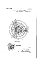
In the drawings: Figure 1 is a longitudinal sectional view of an automatic power transmitting mechanism forming part of the present invention.
Figure 2 is a view taken substantially on the line 2-2 of Figure 1, as viewed when looking in the direction of. the arrows.
Figure 3 is a view of the mechanism shown in Figure 1 as it appears when viewed from the the arrows.
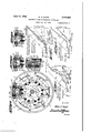
Figure 6 is an end view of the flywheel and 5 associated mechanism disclosed in Figure 4 with a modified form of weight organization associated therewith.
Figure 7 is a sectional view taken approximately on the line 'l? of Figure 6, looking in the direction of the arrows.
Figure 8 is a fragmentary sectional view of one of the weight assemblies shown in Figure 6, with the primary weight in an intermediate position, and with the secondary weight in its retracted position.
Figure 9 is a view similar to Figure 8 with both primary and secondary Weights disposed against the flywheel rim.
Figures 10, 11 and 12 are graphs illustrating the relative pressures existing between the clutch lates of the various modifications of the invention disclosed at different engine speeds, and
Figure 13 is a fragmental view in section illustrating retarding units associated with the centrifugal weights of a slightly different type of automatic clutch mechanism.
Figure 14 is a longitudinal sectional view of a modified form of the power transmitting mechanism forming the present invention.
Figure 14A is a fragmental sectional view of the clutch shown in Figures 13 and 14 and illustrates one of the holdback spring assemblies.
Figure 15 is a view similar to Figure 2, but illustrating a modified arrangement of the weight retarding assemblies.
With continued reference to the drawings, wherein like reference characters designate like parts throughout the several views thereof, and referring more particularly to Figures 1, 2 and 3 thereof, a bell housing I, having a cover or complemental housingmember 2 secured thereto by bolts 3 or the like, houses the clutch mechanism, and theywill both be referred to hereinafter as the clutch housing.
Secured to flange t of the engine or driving shaft 5, by means of bolts 6 or the like is web portion 7 of flywheel 8. Flywheel B is provided with the usual-starting gear 9 on the periphery thereof. Disposed in axial alignment with shaft 5 and mounted for rotation, is driven shaft H which is reduced at 42 at one end and journaled in an anti-friction pilot bearing assembly l3, secured in the flywheel web in well known manner. Shaft ii is adapted-to have the other end operably connected to a suitable gear changing apparatus for amplifying the torque applied to the final driven member, and is journaled in a suitable anti-friction bearing assembly (not shown). Driven shaft H has a splined portion 46, on which a correspondingly splined hub I! is mounted. Hub I1 is provided with a flange Hi to which is suitably secured, as by welding, riveting or the like, a relatively thin metal disk l9,
which constitutes the driven clutch memben' which may consist of any material that has the required. characteristics to give it the correct frictional gripping force,and at the same time has Wearing qualities adapting it for this purpose.
I prefer, however, to employ the lubricated type of material disclosed in the patent to Charles B. Heinrich, Number 1,979,880, issued November 6 1934, which embodies large percentages graphite, and which in practice have given very satisfactory results in a clutch of this character.
.and the driven shaft Frictional facings 2| may be secured to the disk H! in any suitable manner, as for instance by rivets or the like. Each facing 2| cooperates with a suitable annular driving plate for efiecting a driving connection between the driving shaft 5 Plate '22, which is adapted to engage one of the facings, I term the automatic plate for the reason that it is automatically actuated, and plate 23, which is adapted to cooperate with the other facing, is termed the positive plate.
' The construction of automatic plate 22 and its actuating mechanism will now be described. Plate 22 has a strengthening rib 24 formed on the inner periphery thereof, and a similar strengthening rib 25 is provided on its outer periphery.
Ribs 24 and 25 fit over and cooperate with an annular boss 25', preferably formed on the web portion of the flywheel. Annular boss 25 is provided with radial slots which form driving faces and which are adapted to receive radial keys 26, that are formed on plate 22, and are contiguous at their ends, with inner and outer ribs 24 and 25, respectively. The number of keys employed in a particular installation is determined by a consideration of the forces they must transmit, for instance, in the clutch here illustrated, which is designed for relatively heavy work, six equally spaced keys are employed. Each key 26 is bored;
and tapped to receive a threaded holdback bolt 28 which extends through an aperture in the flywheel web. Disposed about each bolt 28 and having one end thereof bearing against the bolt head is a compression spring 29. The other end of each spring 29 bears against a cup or like positioning member 3| which abuts the rear face of the flywheel web. While it is not absolutely essential, it is preferable to provide plate 22 with as many holdback springs as there are driving keys in order that a uniform holdback pressure may be exerted thereupon.
The holdback springs, accordingly, uniformly exert pressure on plate 22 and urge it toward the flywheelweb, and radial keys 26 cooperate with the slots formed in boss 25' to cause plate 22 to rotate with the flywheel, and yet permit its free axial movement.
Ribs 4| serve to give plate 22 rigidity and at the same time constitute heat radiating fins for dissipating heat generated in plate 22,. as will be with reaction faces 42 adapted to abut the face of the flywheel web, and are designed for sliding and fulcruming engagement therewith during operation of the weights. Heads 38 also have their outer sides relieved to provide knife-like edges 43 which are adapted to fulcrum and seat presently described. Heads 38 are also provided of parts in this arrangement since the contact of fedges 43 with plate 22 is of a knife edge pivotal character, and they always fulcrum on the same part of the surface of plate' 22 because they are definitely positioned by ribs 4|. movement present is at the edges of reaction faces 42. The movement is small, however, and plate 22 is accordingly given a smooth and easy movement, and harsh or grabbing clutch action is avoided.
The seats formed by the face of plate 22 and the outer ribs 4| constitute bearing recesses in which edges 43 of weight-heads 3B fulcrum, and
while I prefer to employ this arrangement, it is to be understood that the bearing recesses could The sole sliding be formed in weight heads 38 and the knife edges formed on plate -22, or a member or members secured thereto, if desired without departing from the spirit of the present invention.
Referring to Figure l, the positive plate is shown with the driven member clamped between itand automatic plate 22, and the automatic Weights are disposed in their innermost, or neutral positions. This condition is due to the fact that lever ii is released and allows movement of member 51 under the influence of spring 56, which acts as follows. The left end of spring '56 directly urges plate 23 to the left. The other end of spring 1 acts against disc 56 to so rock levers 6! to cause their fulcruming faces 66 to engage faces 58 formed on member 58. Levers 6!, upon fulcruming about their faces 66 cause their outer ends to move toward the flywheel. This action urges lugs M, and positive plate 23 carried thereby, to the left to bring the positive plate into engagement with. the driven member. With the parts in this position, spring 54 urges cup member 56 against the three point suspension on lever BI and holds it in axial alignment with driven shaft ii. Positive plate 23 accordingly is directly urged into contact with the driven member by one end of spring 56, and the other end of spring 56 reacts against levers (ii to impose an amplified, or multiplied force upon plate 23 to urge it against the driven member. When thrust member 5'! is moved to the left,
throwout levers 6| rotate to cause their fulcrums 67 to cooperate with fulcrum faces Gil formed on members 38, to withdraw the positive plate 3 into declutched position.
Thrust member 57 is caused to move to the left for 'declutching purposes by means of a throwout lever II which is pivoted, by means of a ball and socket connection 1'2, to. a suitable support 13 secured to the clutch housing. The inner end of lever 7i carries an annular bearing Hi thereon which is adapted to cooperate with a smooth polished face 75 of thrust member 51. Bearing 16 may consist of any desirable material, but is preferably constructed of graphite or some other material of a self-lubricating character. The outer end of lever H is connected by a link 16 to one end of a clutch pedal 11 which is pivoted on the vehicle frame as indicated at 18. A latch member 19 provided'with a latching face 80 is pivoted to the vehicle frame in any suitable manner (not shown) and is designed upon selective manual operation to retain. clutch pedal 17, and hence 'lever ll, in automatic position. As shown in Figure 1, latch I9 is disposed in inoperative position-and clutch pedal 1? and lever H are disposed in manually engaged position.
Referring :more particularly to Figure 2 of the drawings, weights 3d are of preferably equal mass,
and are contacted by plungers 89 which are slide ably mounted in. bores in the flywheel rim and are urged inwardly by compression springs 82. Springs 82 react, against plugs 83, threaded into the bores in the flywheel rim. These spring and plunger assemblies will hereinafter be referred each provided with three retarding units.
to as retarding units, because they act so as to retard the movement of weights 3% in response to centrifugal force. Weights at are prevented from being urged inwardly beyond their normal neutral position in response to the action of 'plungers 2i, by means of stops 8% formed thereon. These stops also prevent the weights from swinging past neutral position when the engine is suddenly decelerated.
Modification of the action of the automatic plate actuating means and resulting pressure staging of clutch engagement is effected by providing various groups of weights with various sets of retarding units. For instance, referring to Figure 2, the top and bottom weights are each shown as being provided with a single retarding unit, thus offering but small resistance to the movement of these weights. Another diametrically opposed pair of weights is provided with two retarding units for each weight, and the remaining pair 'of diametrically opposite weights are These weights will hereinafter be termed the first, sec 0nd and third state weights respectively. As the engine or other prime mover is accelerated, the first stage Weights will be the first to operate since the resistance to movement thereof is small. Upon further acceleration of the engine, the sec- 0nd stage weights will then exert their driving force upon plate 22, and finally, when practically non-slipping drive conditions exist, the third stage weights will operate and exert their driving force upon plate 22 and bring the plates together into final or non-slipping engagement. The plates under final. engagement conditions, are accordingly held in engaged condition under the combined influence of the first,'second and third stage weights.
The clutch parts in Figure 1 are shown in positive position, with the automatic weights in their inner or neutral positions which they take when the engine is stationary or operating at idling speeds and with positive plate 23 urged into frictional engagement with the driven member by spring 54. This position of the clutch throwout mechanism corresponds to a fully retracted clutch pedal position.
In practice, the clutch pedal is normally locked or latched in its intermediate automatic position, holding plate 23 in such a position as to establish clearance between the positive and automatic plates and the driven member when the engine is stationary or operating at idling speeds.
When the clutch shown in Figure 1 has the pedal thereof-latched in automatic position and the engine is idling, a clearance exists between the automatic and positive driving plates and the driven member, and the automatic weights are disposed in their innermost or neutral posiand there will be no tendency for them to vibrate or undergo other undesirable movements. The first stage weights operate first because there is less resistance to their movement, than that opposing movement of the second and third stage weights. The retarding units for the first stage weights are designed to allow the first stage third stage of clutch engagement occurs over only weights to force the automatic plate into light frictional driving engagement with the driven member for transmitting a torque of small and slowly increasing magnitude thereto over a substantial speed of the second stage weights. Accordingly, automatic plate 22, under the influence of the primary weights, is given a smooth engaging movement and causes a torque of small, and slowly increasing/magnitude to be transmitted to the driven shaft. The first stage operation, normally takes place at comparatively low engine speeds and is complete or merges into the second stage of clutch engagement, when the speed of the driving member has become sufficiently great for the centrifugal force of the. secondary weights'to overcome the effect of their retarding units and exert substantial driving pressure upon the automatic plate. During the latter part of the first stage of engaging opera-= tion, the secondary stage weights swing outwardly against the action of spring 82, with their heads in operative contact with plate 22, but they normally only exert a slight driving force upon.
' the action of their retarding units and exert their driving force upon automatic plate 22. The automatic plate is now urged into final clutched condition under the combined influences of the first, second and'third stage weights, and hence a comparatively rapid build up of plate pressure occurs during this stage. When weights 36 have moved into contact with the flywheel rim, the plate pressure is suil'icient to prevent slippage between them under any condition, thereby affording a positive driving coupling. It is contemplated that normally the third stage of engaging operation occurs just prior to the final driving conditions when no slippage is desired between the driving and driven members.
It is to be understood that the retarding effects of the various retarding" units may be predetermined by selecting springs of proper strength, or
by adjusting plugs 83 to vary their compression,
and accordingly the first, second and third stages may be caused to overlap each other to any degree desired. In, fact, the stages may be so overlapped, that the merger of one into the otheris so complete, that initiation or completion of the various stages cannot be detected by any torque-speed measurement experiments, thus providing a power transmitting mechanism whose pick-up is smooth throughout the entire clutching operation. If desired, the weights may also.
range, since most of the slippagev should occur during the initial engagement of the clutch members, when. the diflerence in the speeds of the driving and driven shafts is relatively great. The
range prior to operation intocontact with the flywheel rim.
a small portion of the engaging operation speed range, and the build up of pressure in this stage is relatively rapid. Such rapid build up of pressure in the third stage is proper and is desired because at this time the relative speed of the driving and driven members is comparatively low, and comparatively rapid engagement will do no harm in comparatively rapidly synchronizing the driving and driven shafts.
. The provision of building up clutch plate pressures in separate distinct stages, renders the mechanism highly practical and'in combination with the novel facing material employed in my clutch gives a smooth pick-up in slipping drive and a long useful life to the mechanism.
Referring to Figure 10 of the drawings, I have illustrated a diagrammatic representation of the pressure existing between the plates of the mechanism just described, during the different pressure stages, at various engine speeds. Referring to this'figure, lines A, B and C represent the individual pressure exerting effects of each pair of first, second and third stage weights respectively. The projections of lines A and B beyond theirstages, meet at a common point along with line C, because the weights are of equal mass, and any pair of them must exert the same final driving pressure as any other pair. In other words, the respective lines A, B and C represent the final. individual pressure that would be exerted by each pair of first, second and third stage weights if they were each allowed to independently move The resultant curve R, represents the actual plate pressures,
and is obtained by adding the ordinates of each Curve R. graphically illustrates that no plate pressure exists until the engine is individual curve.
accelerated to a speed substantially above idling speed, and the plates are brought into engagement, 3. low pressure build-up occurs in the first stage of clutch engagement, an increased build up of pressure occurs in the second stage, and a, greatly increased build-up of pressure occurs in the third stage of clutch engagement. When full engaging pressure is reached, the curve assumes a horizontal configuration, showing no further pressure build-up, and the plates are in non-slippingengagement under these conditions. This final pressure is maintained under these conditions at a substantially constant value. by virtue of the weights contacting the flywheel rim, and causing the automatic plate to grip the driven member between it and the positive plate against the reaction of the pressure springs of the latter. The weights are therefore restrained from exerting further increased forces upon the automatic plate as the engine is further accelerated. Of course, it will be understood that in practice the curves would probably not be rectilinear, but would probably be of curved configuration. The curves have been here disclosed as straight lines for the purpose of more simply and clearly bringing out the pressure staging functions of the clutch mechanism. v
As has already been stated, the clutch 'engage ment operation in any one stage, and the length of the various pressure stages may be readily modified by varying the resilience of the retardingunits, and in the same graph that has just been described such modified clutch engagement characteristic is shown. Referring to this graph,
speed characteristic of each pair of second and third stage weights when provided with stronger.
" speed range of the prime mover.
shows that final engagement pressure is attained retarding units, and the line R represents the resultant characteristic of the lines A, (which was not changed during the modification of the strength of the retarding units for the second and third stage weights) B and C. It is observed that this characteristic shows a clutch engagement operation wherein one-half of the entire engine speed range, during the clutching operation, is devoted to the first stage of cutch operation, and during this operation, the plate pressure is relatively low and increases slowly with an increase in speed. The second half of this speed range is devoted to the second and third stages of clutch operation, and during these stages the pressure builds up relatively rapidly. By selecting the proper springs for the retarding units, the clutch engaging characteristic may accordingly be given any configuration desired, and perfect clutch engagement obtained.
The line D represents the approximate characteristic that the mechanism would. have if the retarding units were omitted and the weights unrestrained fromfreely moving outwardly in response to centrifugal force, and illustrates a rapid pressure build-up throughout the entire Line D also at a speed that is materially below that for line R, and the speed range during which engagement occurs is accordingly decreased.
The preferred operation of the above described clutch mechanism when installed in a motor vehicle having a conventional three speed transmission, is as follows: The positive plate is maintained in automatic position with the latching means above referred to, and if the vehicle is on level ground, the transmission is placed in high gear and the engine accelerated. As the engine gains speed, weights34 gradually swing outwardly and produce clutch engagement in stages as previously described, ,causingthe driving shaft to transmit a gradually increasing torque to the rear wheels, and the vehicle is started smoothly and without shock. When the vehicle, and consequently the engine, attains sufficient speed, the
weights swing out into contact with the flywheel rim. When this, condition is reached the plates are disposed in non-slipping engagement, and a direct drive from the driving to the driven shaft is thereby automatically effected. When operating the vehicle in this manner, and it is desired to bring-the vehicle to a stop, the accelerator is released and the brakes are applied. When thevehlcle has been decelerated toa speed corresponding substantially to idling speed, through the combined braking action of the engine and brake mechanism, the centrifugal mechanism r'e-- leases the clutch, and the vehicle may be brought to a complete stop by continued application of the brakes, or if traflic conditions permit, the accelerator may be depressed and the engine accelerated to cause almost immediate reengagement of the clutch and the vehicle is again picked up in high gear.
When operating in high gear, or any other gear, for that matter, and a grade is encountered that requires more torque than the engine can deliver in that particular gear under the existing speed conditions, the engine will naturally decelerate of the engine, through the slipping drivebetween .the engine and the rear Wheels, existing at this time, will be accelerated sufiiciently to-develop sufiicient torque to carry the vehicle ,over the grade with a( slipping, torque transmitting drive between the engine andjthe rear wheels, thus doing away with the necessity of shifting into a lower gear in many instances.
As the vehicle gains speed up the grade, or the vehicle again reaches substantially level road, .weights 34 will again exert su fiicient pressure on the clutch plates to establish a non-slipping drive between them. This mode of operation is made possible by the lubricated character of the facing material that is employed in the present clutch mechanism, 'in combination with the effective ventilating and dust removing provisions that are incorporated therein. r
When the automatic plate, in response to the centrifugal weights, has moved to engaging position against the action of its hold back springs, thepositive plate may be withdrawn from the I driven member by manual depression of the clutch pedal. Hence, the plates may be brought out of 'driving engagement to manually disconnectv the driving and driven shafts. In traific, when it is desired toget the vehicle away quickly, and in starting up steep grades, the clutch pedal may be operatedin this manner to disengage the clutch for gear'shiftin'g operations, as in-a vehicle of the type provided with a conventional manually operable clutch. However, it is contemplated to start the vehicle in high gear under normal operating conditions with the present clutch mechanism.
Referring more particularly to the manual dcclutching operation, it is readily appreciated that the torque required to be handled by the clutch, when the vehicle is operating in first or second gear, is much less than that required under normal operating conditions in high gear, due to the torque multiplication provided by such reduction gears. pressures in a clutch of this type are higher than those in conventional manually operable clutch, due to the low coeificient of friction of the facing material employed herein, the required declutching pedal pressure, when the centrifugal weights are in their outermost position, is considerably greater than that required in a conventional man-' ually operable clutch having the usual high frictional coefiicient clutch facings. However, the staging of clutch engagement provided by the present clutch mechanisms does away with the necessity of exerting a heavy pressure upon the clutch pedal during normal gear shifting operations for the reason that it is contemplated that only the first and second stagesof clutch engagement are to be used for such operation. In view of the fact that the plate pressures during the first and second stages of clutch engagement are relatively low, as compared to the final engaged pressure, as previously pointed out, the required declutching pressure will be of a correspondingly low value. Of course, if the vehicle is brought up to a speed correspo' ng to a relatively high engine speed in first 0. second gear, the plates will be forced together under the combined action of the first, second and third stage weights, and the advantage above outlined does-notmanifest itself because the plate pressure at this time is at .a maximum value.
When it is desired to effect clutch engagement and the engine is operating at idling speeds or is stationary, the above mentioned latch mechanism In view of the fact that the engaging may be released to allow the clutch pedal to move into its fully retracted position. This operation allows thrust member 51 to move to the right under the action of spring 54, which, acting through levers 6!, brings positive plate 23 into the position shown in Figure 1, with the driven member clamped between it and the flywheel. A direct coupling is thus manually effected between the driving and driven shafts. Such operation is particularly desirable when the above described mechanism is installed in a motor vehicle, for the reason that when the engine is cold, and the battery is weak, it is sometimes desirable to connect the engine with the rear wheel of the vehicle, so that the vehicle may be towed or coasted in order to turn the engine over.. Moreover,
. should the engine stall, from lack of fuel or any of flowing over the outer face of the automatic other cause, the vehicle can be pulled out of any dangerous location, such as a grade crossing or.
the like, by propelling the vehice with the starting motor.
Since slippage is inherent in the operation of a clutch of this type, heat is generated therein, and
solid lubricant is freed from the facings during operation thereof. This heat and freedmaterial should be eliminated. To this end means are provided for ventilating and cooling the clutch by an air stream, the air stream abstracting heat from the clutch by convection and carrying away the solid freed lubricant therewith. Clutch housing 2 is provided with an aperture 85 having a screen closure member 86, for preventing extraneous matter carried bythe air from being introduced into the clutch mechanism. The air stream induced by the action of fan blades ill, is drawn through screen as and is deflected toward the axis of rotation by means of a bafile member 81, preferably constructed ,of sheet metal. Bafiie 87? is annular in form, and is secured within the clutch housing by means of screws 88 or the like. The air stream, after being deflected toward shaft H by baffle member 8'17, is drawn into the clutch mechanism and a part of the stream, due
to the rotation it is now undergoing caused by rotation-f the associated clutch parts, flows radially over flange M of the positive plate and accordingly cools the flange and a portion of the air stream flows through apertures it in flanges id, and flows over the rear face of the positive plate, thus efliciently abstracting heat therefrom. A portion of the air stream, for instance, when the plates are momentarily disengaged, flows over the engaging'face of positive plate 23 and facing ii on the driven member. A further portion of the air stream passes through the fan blade apertures in driving member l9 and thence between driving face of automatic plate 22 and facing 2| of the driven member l9. Also another part of the air stream flows between the flywheel web and the rear face of the automatic plate,
thereby cooling the parts in this region.
Therefore, both faces of the automatic and positive 'plates are swept over by an air stream,
and both faces of the driven member are likewise similarly cooled. When the plates are in relatively tight engagement, the air stream is divided substantially into two parts, one-half thereflanges 44 formed'on the positive plate,- and the various connecting ribs 45, constitute very eflicient heat radiating fins with which the air streams cooperate/to rapidly remove the heat 'none of their disadvantages.
therefrom. Therefore, warping or' distorting tendencies produced by uneven expansion of the metal which in turn is caused bynon-uniform heat content thereof, are avoided for the reason that the entire area of each of the plates is efiiciently cooled, and is maintained at a substantially uniform temperature. In this connection,
it should be noted that there is no interruption whatever to the exhaust of heated dust laden air from the clutch mechanism, since no clutch cover member is employed.
While the heated, dust laden air removed from the clutch mechanism may be withdrawn or exhausted from the clutch housing in any suitable manner, I prefer toprovide a single aperture 89 therein and associate suitable valves therewith for controlling the air flow from the housing (not here shown).
Another preferred embodiment of my invention consists of the device illustrated in Figures 1, .2 and 3 of the drawings when modified in the following manner.
One of the single retarding units associated with the upper or lower weights 36 illustrated in Figure 2 of the drawings is removed, thus unbalancing the retarding forces acting upon this pair of weights. In view of the fact that this form of the invention is the same as that illustrated in Figure'i, with the exception that one of the single retarding units is omitted, it has not been illustrated in the drawings. The remaining parts illustrated in Figures 1, 2 and 3 are retained in this formof the invention, and the weight, from which the retarding unit was removed, is accordingly only restrained against outward movement by the action of the hold-back springs 29, and it will be referred to hereinafter as the first stage weight. One weight is pro vided with a single retarding unit, and the other groups of weights are provided with two, and three sets of retarding units respectively, and
1 they will be hereinafter termed the second, third and fourth stage weights respectively.
In this form of my invention, the plate clearance, when the parts are disposed in automatic idling position, is slightly greater than that in the mechanism illustrated in Figure l, for the purpose of allowing the automatic plate to tilt in the manner that is to be now set forth.
As the flywheel is accelerated, the first stag weight fulcrums outwardly in response to centrifugal force, and lifts one side of the automatic plate away from the flywheel web against the action of hold-back springs 29, andcomparatively lightly clamps the driven member between it and and the positive plate. The automatic plate tilts during the first stage of engagement operation,
and only a portion of its driving surface engages the driven member. This insures a smooth yielding engagement of these frictional members and this arrangement, in fact, provides all of the advantages of the so-called cushion clutch discs, now appearing on the market, and yet possesses During the first stage of operation, the second, third and fourth stage weights .are held in their neutral positions under the influence of their retarding units. A torque of relatively small magnitude is transmitted to the driven member and the latter is smoothly accelerated.
Upon further acceleration of the flywheel, the I second stage weight, which is located diametrically opposite the first stage weight, and is provided with a single retarding unit, fulcrums outwardly against the action of hold-back springs 29 and into contact with the driven member with a greater force. Automatic plate 22, upon completion 1 of the second stage of engagement operation, is
preferably, though not necessarily, brought into substantially full contact with the driven member under the combined influence of the first and second stage weights.
The third stage of engagement operation is initiated when the third stage weights develop suffic'ient centrifugal force to overcome the effect of their retarding units and fulcrum outwardly. In the event that the automatic plate is not level, or in full driving contact with the driven member at the conclusion of the second stageof operation, the third stage weights act-upon it and bring its surface into engagement with the entire frictional force of the driven member. In the third stage of operation, the plate pressure, and the pressure in spring 54, is built-up fairly rapidly under the influence of the first, second and third stage weights, and a torque of fairly rapidly increasing magnitude is transmitted to the driven member.
. The third and fourth stages are otherwise like the second and third stages of engagement operation of the mechanism illustrated in Figures 1, 2 and 3.
When final or positive driving engagement conditions are reached, the driven member is clamped or frictionally gripped between the automatic andpositive plates, under the action of the centrifugal mechanism and the reaction of spring 54. The driving pressure is uniformly distributed about the entire periphery of the plates because the automatic plate is held in aposition normal to the clutch axis under the influence of the automatic weights, and the latter are disposed against the flywheel rim under these conditions. The driving face of the positive plate is also normal to the clutch axis under these conditions and is urged into contact with the driven member by spring 54.
The automatic plate is therefore disposed parallel to thedriven member when the two are disengaged, tilts into an angular or non-parallel position when clutch engagementis initiated, and tilts back, or is restored to parallel relation with the driven member when clutch engagement is complete.
In the present embodiment of my invention, I prefer to produce tilting actuation of the automatic plate and secure smooth yielding plate engagement by unbalancing the retarding units for the automatic weights in the manner just de-' scribed, but it is to be understood that I may secure substantially the same results by unbalancing the hold-back pressure exerted by hold-back springs 29, by removing or reducing the strength of one or two adjacent springs. Actuation of the automatic weights in this alternative construction produces tilting operation of the automatic uniform hold-back pressure about function in the same general manner.
plate even if the automatic weights are of equal mass and are subjected to equal retarding effects,
because the automatic plate is not subjected to at its entire periphery.
It is also to be understood that my method of engaging clutch plates by tilting one of them during the engaging operation may be applied to positive plate 23, or in fact to the pressure plate of manually operable clutches, for securing a smooth yielding engagement.
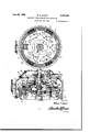
Referring to Figures 4 and 5 of the drawings, I have shown a further modified form of clutch mechanism wherein pressure staging of clutch engagement is effected in a somewhat different manner from that of the clutch mechanism disclosed in Figures 1, 2 and 3 of the drawings. The clutch mechanism proper-is of the same general type as that previously described, and therefore similar reference characters have been applied tolike parts. The flywheel associated with this clutch mechanism is provided with'a plurality of radial slots 24', the walls of which form driving faces and which receive integraL'radially extending keys 26' formed on automatic plate 22. Au tomatic plate 22' is similar to the automatic plate disclosed in connection with Figure 1 except it has no outer .peripheral flange? and heads of the 54 and 54' are installed in the clutch mechanism,
they are sodisposed that spring 54 is under substantial compression when the positive plate is in automatic position, and spring 54' is only loosely disposed in the mechanism with a clearance between the same and its seat formed on member 55'. Accordingly, when the positive plate undergoes movement to the right, it will first be resisted by spring 54 and when it comes in contactwith spring 54', movement thereof will be resisted by both springs. It will be appreciated that throwout lever ll of the present form of the invention may be connected with a clutch pedal and latch arrangement similar to that described in connection with Figure 1.
The automatic weights are identical with those disclosed in the first form of the invention, and Two of the diametrically opposed weights 34' however, are only provided with one section and therefore have less mass than the remaining weights. Weights 34' are not provided with retarding units, and therefore movement thereof is only opposed by the action of holdback springs 29. The remaining Weights are all retarded by prefe'rably three retarding units, which are fcf equal strength. Weights 34 are provided with stop members of the type disclosed in Figure 1 for the purpose of preventing the retarding units from urging them inwardly beyond their neutral positions. Since weights 34 are not acted upon by retarding units, no stops are provided thereon.
The operation of this clutch mechanism will now be described. When the engine or other prime mover is operating substantially at idling speed, and the positive plate is disposed in automatic position, the. weights are in their neutral positions, and the driving and driven shafts :are disconnected. As the engine is accelerated, weights 34 swing outwardly about their pivots 43 against the action of holdback springs 29 causing automatic plate 22 to move over into light driving engagement with the driven member and I a torque of small, and slowly increasing magni-- sure builds up to a predetermined pressure un-' der the influence of weights 3d and weights 3d than exert pressure upon the automatic plate. Weights 38, prior to this time, have already moved outwardly and have their fulcrums 63 hearing lightly against plate 22, but have been held in check bytheir retarding units.
When weights 3:3 commence to exert an infiuence upon an automatic plate 22, the first stage of clutch engagement operation may be said to be at an end and the second stage initiated. During the secondstage of engagement operation weights wand 35' act upon the automatic plate, and the plate pressure builds up at an increased rate. Plate pressure in'the secondary stage of the clutch engagement builds up at a predetermined rate, depending upon the retarding efiect exerted upon the weights it by their retarding units, which may be varied by adjusting the spring pressure thereof.
During the first and second stages of clutch engagement that have just been described, it is preferable that movement of positive plate 23 is opposed or is resisted solely by spring 553. The parts are so designed that spring 54, carried by positive plate -23, does not contact with its seat on collar 5% until the second stage operation has been completed.
The second stage of clutch engagement is accordingly preferably terminated when plate 23 has been moved sufilciently under the influence of weight-.533 and 3% to cause spring 58 to conmovement of positive plate 231s now resisted by springs 5d and 54'. During the third stage of clutch engagement, the relative speed of the driving and driven members is relatively small, and therefore a rapid build up of pressure is desirable to rapidly secure a non-slipping drive. When final engaging pressure conditions have been reached, the weights are in engagement with the flywheel rim and exert no further increasing iorces upon the automatic plate, and the plates are thendisposed in non-slipping engage- 'ment. If desired, for instance in a light motor vehicle, spring 5d may. be omitted and spring 5d accordingly stifiened, thus doing away with the third stage clutch engagement and producing a two stage clutch mechanism, although it is preferable in heavy vehicles to employlthree or more pressure stages for giving smooth clutch operation.
"The other details of operation of this mechanism are the same as those described in connection with the mechanism illustrated in Figure 1.
Referring to Figure 11 of the drawings, I have graphically illustrated the relation that exists between plate pressure and engine speeds of the mechanism just described from initially engaged to fully engaged conditions. Lines A-and B are drawn, assuming for the moment, that springs 5d, 54' have been replaced by a single theoretical spring T, that is stronger than either of springs 54 or 5% and which will give a final reaction pressure equal to that exerted by springs 55 and 5d acting concurrently. Line A represents the pressure exerted byweights 3d during the first stage of clutch engagement under the theoretical conditions imposed, and this line produced represents the total driving pressure that weights 3G can exert by moving outward into contact with the flywheel rim, under the same theoretical conditions. Line 28 represents the pressure ex- 0 erted by the weights 3% throughout their period of operation.
The operation under theoretical conditions will now be described. Line A represents the first stage of clutch engagement, and under these conditions a torque of small magnitude is transmitted by the automatic and positive plates to the driven member, and during the second stage weights 3% augment the action of weight 3% and cause pressure to build up at a fairly rapid rate until full driving pressure conditions are reached. The operation that has just been described is seen to be exactly the same as that shown in Figure 19 of the drawings except for the fact that in the present instance, under the theoretical conditions imposed, only two stages of clutch operation are effected.
Assuming now, that theoretical spring T is removed and replaced by springs 5d and 5d, the operation under these conditions will be set forth; In view of the fact that spring M is not as strong or stilt as theoretical spring T, line A, which pressure as that present during the theoreticalmode of operation just described, and the pressure between the plates accordingly, will not build up as rapidly. When the engine has attained a predetermined speed, weights come into play, and their action is illustrated byline 18. Line A will therefore merge into line A'+B, the latter being the resultant of lines A and B. The pres- Evil) sure during the second stage, builds up at a greater rate. than during the first stage of clutch engagement operation. When the engine speed has become sufliciently'great, and the positive plate has been displaced suficiently for secondary backing spring 543' to come into play and oppose movement of the positive plate, the pressure between the plates will build up at a still greater rate, as illustrated by the curve C, and when the third stage oi cluch operation is terminated, the plates are disposed in engagement ,under full driving pressure, under the combined influence of weights 3d and 3d and the combined reaction of springs M and can This graph may be proved in the following manner: In view of the fact that the line A represents the full pres== sure exerting-effect of springs lid when they are disposed in their limit of engagement with'the flywheel rim, and line B represents the full driv- I when added together should result in the driving pressure, and by consulting this maple it will be seen that this condition emsts. c-1+, the ordinates of lines A'+B at the junction d the second and third stages should be equal to the ordinate oi line A, at the same engine speed, plus the ordinate of line B at that point, and an inspection of this graph will show that this con- Referring to Figure 6, first stage weights 9i have weight levers 36 secured to the outer face thereof. Shouldered studs 92 'extend through apertures formed in levers 36 and are threaded into weights 9!. Second stage weights 93 are U-shaped in cross section to fit over the first stage weights and are provided with aligned apertures at which receive studs 92, and are slidably mounted thereon. Relatively light compression springs 95 encircle studs 92 and react at one end against a pin 96 and at their other ends seat in recesses 8'5 formed in weights Q3. Springs W are primarily employed for urging weights 83 towards the flywheel rim and in contact with levers 36, but have a further function that will presently. appear. wardly is resisted by eons of retarding units which consist of plungers 98 having a fiange formed thereon, and which abut the bottom of an enlarged recess 99 formed in the flywheel rim. Plungers 98 are placed under compression by means of springs liil, which seat in recess 99 and bear against the 'plungers. Springs it! are held in place in recesses 89 by means of threaded plugs m2. It is to be understood that, if desired, the type of retarding units disclosed in connection with the previously described mechanisms could be used in the present invention. However, it is preferable to positively limit the inward movement of the plunger-s so that they will not act' act upon weights 93 sufiiciently to move them in wardly against the action of springs 95.
' The operation of this clutch mechanism is as follows: With the centrifugal mechanism shown in Figures 6 to 9, inclusive, incorporated with a clutch mechanism similar 'to that in Figure 1,
wherein only a single spring backs-up the positive plate, clutch engagement will occur in two stages. With the automatic plate held in automatic position in the manner previously described, the engine or other prime inover is accelerated, and when a predetermined speed has been attained, first stage weights 9| move outwardly abouttheir pivots 43 against the action of hold back springs 28, and also against the ac-' I tion of springs 95, which act on studs 92 to resist V outward movement of the first stage weights to cause the automatic plate to engage the driven member." Due to the small mass of weights 9|,
the plate pressure is low and slowly increases- 7 during their operation. Duringoperation of the flrststage weights, the second, stage weights haveremained in ,their inner positions due to theretarding action of plungers 98, and have] only rotated toe slight extent due to the slight rotation Motion of weights at outmenace of their-supporting studs 92, produced by movemerit of first stage weight M. It is preferable to so design the second stage retarding units so that just priorto engagement offirst stage weights 9! with the flywheel rim, second stage weights 83 will overcome the resistance of their retarding units, and will engage the lower face of lever 25. Thereafter, movement of weights at v and 93 is concurrent, and their combined centriforce to further overcome the pressure built up in the backing spring for the positive plate at this time. Accordingly, when weights 9! reach the 1 positions, where they cannot, by themselves, produce further movement of automatic plates 22, the first stage of clutch engagement may be said to be at an end. When weights 93- contact the lower faces of levers 36, the second stage of clutch engagement is initiated. During the second stage of clutch engagement, weights 9| and 93 exert their combined forces upon automatic plate 22, and the pressure built up between the plates is more rapid than that present in the first stage of clutch engagement. When both weights contact the flywheel rim, as shown in Figure 9, the pressure is sufdciently high to force the plates into non-slipping engagement, and the driving and driven shafts are then directly coupled.
Referring now to Figure 12 of the drawings, the relation between plate pressure and engine speed of the mechanism just described is graphically shown. Curve A represents the pressurespeed relation of the first stage weights SH, and the projection of this curve illustrates the maximum pressure that may be exerted by these weights. Curve 3 represents the pressure-speed relatlonsof the second stage weights 93. The line A+B represents the actual plate pressure over the entire engagement operation, and is obtained by adding the ordinates of the projection of curve A, to the corresponding ordinates of curve B. The graph shows two pressure stages of approximately equal speed ranges, and during the first stage, the plate pressure is low and slowly increases, and in the second stage a relatively rapid build up of pressure occurs.
In the event that movement of positive plate 23 is opposed by two springs 54 and 54' as shown in Figure 4, the present weight organization will provide three pressure stages in a manner similar to that obtained in the mechanism illustrated in Figure 4, and the resultant pressure-speed curve of such mechanism will be similar to that disclosed in Figure 11 of the drawings. Line D is similar to line D 01. Figure of the drawings.
Although I'have disclosed spring pressed plungers for retarding the action of the centrifugal weights to produce pressure staging of clutch designing or adjusting the retarding units, and prefer to effect this result in this manner. It is to be understood, however, that if desired, the centrifugal weights may be designed to be larger or smaller than those here disclosed, and/or the pressure of the hold back springs 29 may be varied for the purpose of further modifying the operating characteristics of the mechanisms,
without departing from the spirit of the present invention.
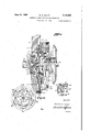
Referring now to Figures 13 and 14 I have disclosed a modified form of automatic power transmitting mechanism of the character shown in pending application of Robert P. Lewis, Serial No. 634,047, filed September ZU, 1932, but which has been modified in accordance with the present invention to effect pressure staging of clutch engagement in accordance with the present invention. A driving shaft Mt at its rear end is provided with a bore # 95 and a. flange Hi6 which secured by means of bolts it? to a flywheel 588. Supported within bore M by a bearing its is the reduced end of a driven shaft Mil provided with splines i it upon which is mounted for reciprocation a hub H2 having a flange H3.
Secured to hub flange M3 by means of rivets EM or the like is a driven disk H5 upon the periphery of which are mounted frictionfacings 2!. The face of flywheel 53$ cooperates directly with one of the facings 2i provided on driven member H. The other facing 2! of member I! coopcrates with an automatic plate l22, which is provided with a pluralityof rectangular recesses in which the heads 38 of centrifugal weights 3% fulcrum in the manner previously described. Automatic plate I22 and a reacting plate I23 are driven by the flywheel, and are accordingly keyed thereto by means of a series of plates l24 secured to flywheel I08 by bolts 925 and extending within slots 826 provided in automatic plate 522. Levers 36 extend through slots in reaction plate E23, which is'provided with a flange I21. Retarding units are provided in flange H21 and i cooperate with weights St to oppose movement tracting the centrifugal weights 34 when the thereof. 1
Reaction plate E23 is resiliently backed by means of compression springs 228 which act between a plate i255 bearing against reaction plate .side walls of a saddle member I35. Each throwout lever is designed for rocking movement within its saddle member l35 which is secured to the flywheel M8. The inner end of each throwout lever is disposed between plate 13! previously described and a throwout bearing assembly I35 which is actuated by means of throwout fork assembly-l3l which extends outwardly beyond theclutch housing. In this instance clutch pedal T1 (not shown) may'be mounted directly upo throwout fork I31.
In Figure 14A there is disclosed one of the hold--' back assemblies for urging automatic plate H2 and reaction plate I23 toward each other for reparts are decelerated to idling speeds. Threaded into plate I22 is a shouldered stud M0 which ex- .tends through an aperture in plate l 2?. A comand automatic plates toward each other, they constantly grip the heads 38 of the centrifugal weights and maintain them in the retracted position shown in Figure 14 when the engine is operating at idling speed or is stopped.
A disclosure of this organization has been made to illustrate the adaptability of my pressure staging mechanism to this type of power transmitiii ting device, and it is contemplated that all of the V methods of eiTecting pressure staging previously disclosed maybe effectively carried out in mechanisms of this character. In the present instance, I have disclosed flange EZQ of reaction plate E23 provided with retarding units of the type employed in the mechanisms illustrated in Figures 1, 2, 3, 4 and 5 of the drawings, and accordingly the methods of pressure staging disclosed in those figures may be readily effected in this mechanism.
' The resilient backing means provided for the reaction plate Inay also be designed to act in sequence and the additional pressure stage described in connection with Figures 4 and 5 accordingly obtained. It is also to be understood that the weight and lever organizations disclosed in Figures 6, '7, 8 and 9 may be effectively employed in the mechanism shown in Figure 13 if' desired.
From the above detailed disclosure, it is seen that I have provided automatic power transmitting mechanisms that are relatively simple in design, have but few parts, may be cheaply manufactured, and which may be so designed or adjusted so as to have various operating characteristics to adapt them to the requirements of any particular installation. Moreover, these mechanisms, due to the pressure staging, or controlled clutch engagement effected by them, are especially adapted for use in motor vehicle drives, where such units are usually subjected to severe abuse by negligent or careless operators.
The invention may be embodied in other specific forms without departing from the spirit or essential characteristics thereof. The present embodiments are therefore to be considered in all respects as illustrative and not restrictive, the scope of the invention being indicated by the appended claims rather than by the foregoing description, and all changes which come within the meaning and range or equivalency of the claims are therefore intended to be embraced therein.
What is claimed and desired to be secured by.
United States Letters Patent is:
1. An automatic power transmitting mecha nism comprising, a driving member; a driven member; speed responsive means operably 3,550 ciated with said driving member for causing pressure to build upslowly between said driving and driven members as said driving member is accelerated to a predetermined speed, and for cans-- ing said pressure to build up at a greater rate when said driving member reaches a second predetermined speed, and reaction means for causing said pressure to build up at a still greater rate as said driving member is accelerated to a stillhigher speed.
2. In an automatic power transmitting mocha- -nism, a driving member; a centrifugally operable said driving member attains a predetermined speed, and for causing the area of surface en- .tive plate; a plurality of spring means operably associated with said plate and arranged to sequentially act thereupon to oppose movement thereof; and means for sequentially imposing multiplied reactions of said spring means upon said plate.
4. An automatic power transmitting mechanism comprising a driving member; a driven member; said members having cooperating friction surfaces; means mounting said driving and driven members for engagement and disengage ment; and means for automatically bringingsaid driving and driven members together, into tilted relationship with a portion of the area of said friction surfaces in driving engagement when gagement to progressively increase as said driving member is accelerated above said predetermined speed.
b. In a clutch mechanism, a driving member; a driven member; said driving and driven members having friction surfaces and mounted for engagement and disengagement; and meansfor automatically tilting said driving member and bringing a portion of its friction surface into driving engagement with the friction surface of said driven member when said driving member attains a predetermined speed, and for thereafter progressively increasing the area of contact of said friction surfaces as said driving member is further accelerated until the latter are in full engagement.
6. In a clutch, driving and driven members mounted for engagement and disengagement; a plurality of outwardly movable elements operable to force said members into engagement; means for-automatically actuating said elements when said driving member attains a predetermined speed; and centrifugally operable means for automatically applying further actuating forces to. said elements when said driving member attains a speed greater than said predetermined speed, to thereby effect pressure staging of-clutch operation. I
7. The mechanism set forth in claim 6, wherein said first and second named actuating means comprises centrifugally operable masses operable to apply actuating forces to said elements.
8. In a clutch, driving and driven members mounted for engagement and disengagement; a plurality of outwardly movable elements operable to force said members into driving engagement; and primary and secondary actuating means for automatically applying forces of comparatively low magnitude to said elements when said driving member is accelerated to a predetermined speed, and for applying forces of comparatively great magnitude to said elements when said driving member attains a higher predetermined speed.
9. In an automatic clutch, in sub-combination, a pair of members mounted for synchronous rotation and for movement toward. and away from each other; a movable element operable to separate said members; means for automatically applying comparatively small actuating forces to said element when said members are accelerated a higher predetermined speed range.
to a predetermined speed; and means for applying actuating forces of larger magnitude to said element when said members attain a higher predetermined speed.
10. The device described in claim 9, wherein said actuating means comprises at least two centrifugally operable members arranged to operate in sequence and apply actuating forces to said element.
11. In a clutch, in sub-combination, a pair of rotatable members mounted for relative axial movement and adapted to normally effect clutch engagement when they are separated; a movable element for separating said members; means for applying actuating forces of comparatively small magnitude to said element when said members for relative movement toward and away from .each other; a movable element for separating said members; a primary centrifugally operable weight for automatically applying actuating forces to said elementwhen said members are accelerated through a predetermined speed range; a secondary centrifugally operable weight adapted to apply actuating forces to said element; and means for causing said secondary weight to apply actuating forces to said element only when said members are accelerated through 14. The device described in claim 13, wherein vsaid secondary weight is operably associated with said element by lost motion connecting means. 15. The device described in claim 13, wherein .said primary weight is connected for synchronous movement with said element. I
16. The device described in claim 13, wherein said last named means comprises means opposing the action of said secondary weight in response to centrifugal force.
17L In a clutch, driving and driven members mounted for engagement and disengagement; means for automatically bringing said members into engagement when one of them attains a predetermined speed; means for' establishing and building up a yielding engagement pressure between said members in stages when they are automatically engaged, comprising primary and means being operable to cause said driving member to tilt when it is being initially engaged with said driven member.
19.'The device described in claim 18, wherein said engaging means comprises means automatically operable in response to variations in.
the speed of one of said members.
20. The device described in claim 18, wherein said engaging means comprises speed-responsive means automatically operable to engage said members when said driving member attains a predetermined speed, and wherein the last named means of claim 18 comprises means for modifying the action of said speed-responsive means.
21. In a clutch, a driving member mounted for movement toward and away from a driven member and being normally parallel thereto when it is disengaged therefrom; means for causing said driving member to advance toward said driven member and tilt to thereby bring only limited portions of their areas into contact when they are initially engaged; and means for causing said members to come into full surface engagement.
22. The device described in claim 21, wherein said first named means comprises a centrifugally operable mechanism.
23. The device described in claim 21, wherein said first and second named means comprise primary and secondary centrifugaliy operable mechanisms, operable in sequence as the driving member is accelerated to apply engaging force thereto.
24. An automatic clutch comprising a driving member, a driven member, a pressure plate revolving with the driving member and movable to engage the driven member, a spring mounting ring associated with the pressure plate, preloaded pressure springs acting against the spring mounting ring, clutch throwout mechanism operable at will to move said spring mounting ring against the pressure of the preloaded pressure springs, spring means, tending to hold the pressure plate retracted to a fixed position relative to the spring mounting ring, centriiugally' energized means adapted to force said pressure plate away from the spring mounting ring into initial engagement with the driven member, and other centrifugally energized means responsive only to a higher rotative speed than the first mentioned centrifugally energized means, for shifting the spring mounting ,-means to transfer the pressure spring load from the throwout mechanism to the pressure plate whereby. to obtain full clutching engagement under the predetermined preloading pressure of the pressure springs.
25. An automatic clutch comprising a driving member, a driven member, a pressure plate revolving with the driving member and movable to engage the driven member, a spring mounting ring associated with the pressure plate, preloaded pressure springs acting against the spring mounting ring, clutch throwout mechanism operable at will to move said spring mounting ring against the pressure of the preloaded pressure springs, spring means tending to hold the pressure plate retracted to a fixed position relative to the spring mounting ring, centrifugally energized means adapted to force said pressure plate away from the spring mounting ring into initial engagement with the driven member, other centrifugally energized means responsive only to a higher rotative speed than the first mentioned centrifugally energized means, for shifting the spring mounting means to transfer the pressure spring load from the throwout mechanism to the pressure plate whereby to obtain full clutching engagement under the predetermined preloading pressure of the pressure springs, said throwout mechanism being shiftable to engage or disengage the clutch contrary to the automatic control thereof.
26. An automatic clutch comprising, a driving member, a driven member, a pressure plate revolving with the driving member and movable to engage the driven member, a spring mounting ring associated with the pressure plate, preloaded pressure springs acting against the spring mounting ring, clutch throwoutmechanism operable at will to move said spring mounting ring against the pressure of the preloaded pressure springs, spring means tending to hold the pressure plate retracted to a fixed position relative to the spring mounting ring, centrifugally energized means adapted to force said pressure plate away from the spring mounting ring into initial engagement with the driven member, other centriiugally energized means responsive only to a higher rotative speed than the first mentioned centrifugally energized means, for shifting the spring mounting means to transfer the pressure spring load from the throwout mechanism to the pressure plate whereby to obtain full clutching engagement under the predetermined preloading pressure of the pressure springs, said throwout mechanism being shiftable to a position to advance the spring mounting ring and pressure plate and thereby force the pressure plate into driving engagement with the driven member independently of the action of the centrifugally energized means.
27. An automatic clutch comprising a driving member, a driven member, a pressure plate revolving with the driving member and movable to engage the driven nembena spring mounting ring associated wtih the pressure plate, preloaded pressure springs acting against the spring mounting ring, clutch throwout mechanism operable at i will to move said spring mounting ring against the pressureof the preloaded pressure springs, spring means tending to hold the pressure plate retracted to a fixed position relative to the spring mounting ring, centrifugally energized means operatively engaged between the pressure plate and the spring mounting ring adapted to force said pres- 28. An automatic clutch comprising a driving member, a driven member, a pressure plate revolving with the driving member and movable to engage the driven member, a spring mounting ring associated with the pressure plate, preloaded pressure springs urging the spring mounting ring towards the pressure plate, clutch throwout mechanism operable at will to move said spring mounting ring against the pressure of the preloaded pressure springs, spring means tending to move the pressure plate retracted to a fixed position relative to the spring mounting ring, centrifugally energized means operatively engaged between the pressure plate and the spring mounting ring adapted to force said pressure plate away from the spring mounting ring into initial engagement with the driven member, other centrifugally energized means responsive only to a I higher rotative speed-than the first mentioned centrifugally energized means, for shifting the spring mounting means to transfer the pressure spring load from the throwout mechanism to the pressure plate whereby to obtain full clutching engagement under the predetermined preloading pressure of the pressure springs, said throwout mechanism being shiftable to engage or disengage the clutch contrary to the automatic control thereof.
29. An automatic clutch comprising a driving member, a driven member, a pressure plate re volving with the driving member and movable to engage the driven member, a spring mounting ring associated with the pressure plate, pressure springs urging the spring mounting ring towards the pressure plate, clutch throwout mechanism operable at will to move said spring mounting ring against the pressure of the pressure springs, spring means tending to hold the pressure plate retracted to a fixed position relative to the spring mounting ring, a plurality of centrifugally energized means operatively engaged between the pressure plate and the spring mounting ring and varying responsive to a plurality of predetermined rotative speeds, a part only of said plurality of means being adapted to first take up running clearances by advancing the pressure plate into contact with the driven member at the lowest predetermined speed and all of said plurality of means being operable to subsequently transfer the preloaded pressure spring load from thethrowout mechanism to the pressure plate at a predetermined higher rotative speed whereby to cause full clutch engagement under a predetermined spring load.
'30. An automatic clutch comprising a driving member, a driven member, a pressure plate revolving with the driving member and movable to engage the driven member, a spring mounting .ring associated with the pressure plate, pressure up running clearances by advancing the pressure plate into contact with the driven member at the lowest predetermined speed and to .subsequently transfer the preloaded pressure spring load from the throwout mechanism to the pressure plate at a predetermined higher rotative speed whereby to cause full clutch engagement under a predetermined spring load, said throwout mechanism being shiftable to" engage or disengage the clutch contrary to the automatic control thereof.
WILLIAM E. HAUPT.
Priority Applications (1)
| Application Number | Priority Date | Filing Date | Title |
|---|---|---|---|
| US653875A US2121663A (en) | 1933-01-27 | 1933-01-27 | Automatic power transmitting mechanism |
Applications Claiming Priority (1)
| Application Number | Priority Date | Filing Date | Title |
|---|---|---|---|
| US653875A US2121663A (en) | 1933-01-27 | 1933-01-27 | Automatic power transmitting mechanism |
Publications (1)
| Publication Number | Publication Date |
|---|---|
| US2121663A true US2121663A (en) | 1938-06-21 |
Family
ID=24622624
Family Applications (1)
| Application Number | Title | Priority Date | Filing Date |
|---|---|---|---|
| US653875A Expired - Lifetime US2121663A (en) | 1933-01-27 | 1933-01-27 | Automatic power transmitting mechanism |
Country Status (1)
| Country | Link |
|---|---|
| US (1) | US2121663A (en) |
Cited By (1)
| Publication number | Priority date | Publication date | Assignee | Title |
|---|---|---|---|---|
| US2456942A (en) * | 1944-01-26 | 1948-12-21 | Worcester Polytech Inst | Power transmission for helicopter rotors |
-
1933
- 1933-01-27 US US653875A patent/US2121663A/en not_active Expired - Lifetime
Cited By (1)
| Publication number | Priority date | Publication date | Assignee | Title |
|---|---|---|---|---|
| US2456942A (en) * | 1944-01-26 | 1948-12-21 | Worcester Polytech Inst | Power transmission for helicopter rotors |
Similar Documents
| Publication | Publication Date | Title |
|---|---|---|
| US2107954A (en) | Clutch and transmission mechanism | |
| US2084219A (en) | Power transmission mechanism | |
| US2090265A (en) | Automatic clutch | |
| US1841284A (en) | Friction clutch | |
| US2613778A (en) | Multiple friction clutch | |
| US2121663A (en) | Automatic power transmitting mechanism | |
| US2090397A (en) | Automatic clutch mechanism | |
| US2171829A (en) | Automatic drive and clutch mechanism | |
| US2232454A (en) | Automatic power transmitting mechanism | |
| US2691437A (en) | Centrifugally and manually operated servo clutch | |
| US2281118A (en) | Rotor brake | |
| US2007304A (en) | Automatic power transmitting mechanism | |
| US2001931A (en) | Automatic clutch | |
| US2326279A (en) | Automatic clutch mechanism | |
| US2023690A (en) | Automatic clutch | |
| US2072117A (en) | Clutch mechanism | |
| US2972909A (en) | Automatic change speed gears | |
| US2045612A (en) | Automatic power transmitting mechanism | |
| US1910141A (en) | Clutch | |
| US1793735A (en) | Automatic accelerating friction clutch | |
| US2208111A (en) | Clutch mechanism | |
| US2045611A (en) | Automatic power transmitting mechanism | |
| US1740265A (en) | Automatic clutch-control mechanism | |
| US2091919A (en) | Power transmission mechanism | |
| US1969661A (en) | Transmission |