US21130A - Locomotive steam-engine - Google Patents
Locomotive steam-engine Download PDFInfo
- Publication number
- US21130A US21130A US21130DA US21130A US 21130 A US21130 A US 21130A US 21130D A US21130D A US 21130DA US 21130 A US21130 A US 21130A
- Authority
- US
- United States
- Prior art keywords
- engine
- cylinder
- motion
- steam
- pump
- Prior art date
- Legal status (The legal status is an assumption and is not a legal conclusion. Google has not performed a legal analysis and makes no representation as to the accuracy of the status listed.)
- Expired - Lifetime
Links
- 230000003137 locomotive effect Effects 0.000 title description 7
- 230000004048 modification Effects 0.000 description 5
- 238000012986 modification Methods 0.000 description 5
- 238000009432 framing Methods 0.000 description 1
- 230000000630 rising effect Effects 0.000 description 1
- 238000004326 stimulated echo acquisition mode for imaging Methods 0.000 description 1
- 239000000725 suspension Substances 0.000 description 1
- XLYOFNOQVPJJNP-UHFFFAOYSA-N water Substances O XLYOFNOQVPJJNP-UHFFFAOYSA-N 0.000 description 1
Images

Classifications
-
- F—MECHANICAL ENGINEERING; LIGHTING; HEATING; WEAPONS; BLASTING
- F01—MACHINES OR ENGINES IN GENERAL; ENGINE PLANTS IN GENERAL; STEAM ENGINES
- F01L—CYCLICALLY OPERATING VALVES FOR MACHINES OR ENGINES
- F01L21/00—Use of working pistons or pistons-rods as fluid-distributing valves or as valve-supporting elements, e.g. in free-piston machines
- F01L21/02—Piston or piston-rod used as valve members
-
- E—FIXED CONSTRUCTIONS
- E02—HYDRAULIC ENGINEERING; FOUNDATIONS; SOIL SHIFTING
- E02D—FOUNDATIONS; EXCAVATIONS; EMBANKMENTS; UNDERGROUND OR UNDERWATER STRUCTURES
- E02D7/00—Methods or apparatus for placing sheet pile bulkheads, piles, mouldpipes, or other moulds
- E02D7/02—Placing by driving
- E02D7/06—Power-driven drivers
- E02D7/10—Power-driven drivers with pressure-actuated hammer, i.e. the pressure fluid acting directly on the hammer structure
Definitions
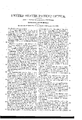
- FIG. 1 represents a side elevation of a locomotive engine embracing my improvements.
- Fig. 2 represents a transverse section through the boilers, cylinder and steamchest of a locomotive engine, showing a modification in the arrangement of the steam chest valves, and steam pipe.
- Fig. 3 represents a plan of the frame and drivers of a locomotive engine showing a modification in the arrangement of the eccentrics and valve gearing.
- Fig. 4 represents a side elevation of an engine with the same modifications as those shown in Figs. 2 and 3.
- Fig. 5 represents an elevation of the trunnion boxes and guides, showing the manner in which they may be adjusted.
- Fig. 6 represents a modification in the plan of supporting and giving motion to the main driving cylinder.
- My improvements consist, first, in supporting and arranging the cylinders of a steam engine, so that it is free to move at right angles to the direction of motion of its piston rod, and in a plane parallel to the plane of motion of the cranks connected with the rod. Second. In connecting each end of the piston rod of an engine, with separate drivers, and giving motion to both drivers in the same direction without the aid of intermediate pitmen or links; by arranging the piston rod so that it passes through both heads of the cylinder, in connection with giving motion to the cylinders at right angles to the line of motion of the piston rod. Third.
- the boiler of the engine is connected with the framing, in the usual manner, and supported by two sets of driving wheels, both of whose axles (z) are crank axles with inside connections.
- Two cylinders (G) are arranged below the boilers, and between the axles of the drivers; and instead of being permanently attached to the boiler or frame, as heretofore, are connected, with the boiler by sliding steam pipes (I), which leaves the cylinder free to move in a vertical plane.
- a piston rod (R) passes through both heads of the cylinders, and is connected, directly at either end, with the cranks of. both pair of drivers, without an intermediate pitman.
- trunnions (A) are cast, which have their bearing in boxes (D) and slide in guides (G) on each side, rising and falling with the cranks as the piston reciprocates back and forward.
- These guides serve to steady the motion of the cylinder and prevent it being drawn in either direction by the motion of the piston, while at the same time the trunnions admit of its oscillating, in a slight degree, in a vertical plane, that it may accommodate itself to, and be in line with, the cranks; as one or the other driving wheels pass into a low, over a high place in the track.
- the boxes (D) for the trunnions may be arranged so that as they wear in the guides, they may be adjusted to preserve their parallelism to the guides, and to retain the center of the trunnions in the center of guides, by means of double keys or wedges (B) on each side between which passes a screw bolt (a), with a cap on each end. The adjustment is made by filing down the small end of each key, and tightening the screw bolt.
- the sliding steam pipes (I) pass through stuffing boxes (3)) into a pipe (PP), leading from the steam chest (N) and through these pipes the steam passes to give motion to the piston.
- the steam chest (N) and slide valve (V), in the present instance, are fixed to the boiler; but they may be arranged as shown in Figs. 2, 3, 4:, and 5, in which they are made fast to the cylinder (C).
- a single sliding steam pipe (P) is required to connect the cylinder with the boilers, and is placed above the center of vibration of the cylinder, and connected with it by a ball joint (0), which admits of the cylinder inclining without disturbing its connections with the boiler.
- a secondary cylinder (IQ) is fixed to the boiler over the main cylinder; its piston rod is connected with the main cylinder at its center, and gives to it a positive motion at right angles to the motion of its piston; thus supporting the main cylinder, relieving the cranks from its weight, and carrying the cranks over the dead center.
- the slide valves of the main cylinder are operated by the expansion gear in general use.
- the valves of the secondary cylinder are connected by a link (3 with the quadrant block (1)) of the main expansion gear, so that the valves of both cylinders move simultaneously; and in reversing the valves of the main cylinder, those of the secondary cylinder are also reversed.
- the expansion gearing is reversed by an eccentric (JJ) attached to the side of the fire box, whose rod connects, by an intermediate lever (TT), with the quadrant (SL) of the expansion gearing.
- JJ eccentric
- TT intermediate lever
- SL quadrant
- the eccentric is turned by a hand lever (00) in the usual manner.
- a feed pump (WV.P.) for supplying the boiler with water may be arranged either on the interior or exterior of the boiler.
- a slotted link (PL) of peculiar form, is pivoted to the side of the boiler, and also to the piston rod (PG) of the pump, and the opposite end is supported by a link (EH) when out of gear with the eccentric.
- the pump is worked, when the engine is in motion, by an eccentric (EE) on the driver, whose rod (A) is connected by a block (F) with the slotted link (PL). From this block (F) a rod (T) extends back to the fire box, so that the position of the block may be varied by the engineer, when the engine is in mo- -tion, and thus increase or diminish the length of stroke of the pump, as occasion may require.
- the sliding block (F) is held in place when the length of stroke of the pump is adjusted by notches on the under side of the rod (T) which catch on a toothed plate on the side of the fire box.
- the pump By sliding the block (F) in the slotted link, forward to the vertical part of the slot, the pump is thrown out of gear with the eccentric.
- the pump may be worked by moving the block back and forward in the slotted link, with the hand gear, or it may be thrown out of gear with the eccentric, and worked with a brake, for which a socket (7) may be made on the link.
- valve gearing When the steam chest is connected with the main cylinder, a different arrangement of valve gearing may be used such as is shown in Figs. 3 and 4in which the cocentrics (E) are cast in one piece, and slide laterally on the axle of the driver.
- An eccentric rod (J) with a slotted cross head (J) receives a slide (9) on the end of the valve stem, and as the cylinder rises and falls the slide moves in this slot.
- cam yokes (Q) are attached, and over the yoke, on each side, are guide hooks (M) which catch the eccentrics, as they all slide laterally on the axle, and throw the eccentric rod in position for the cam to enter the yoke and reverse the motion of the engine.
- the hooks are operated by a hand gear by which they are thrown down to catch the cam when the engine is reversed.
Landscapes
- Engineering & Computer Science (AREA)
- General Engineering & Computer Science (AREA)
- Mechanical Engineering (AREA)
- Life Sciences & Earth Sciences (AREA)
- General Life Sciences & Earth Sciences (AREA)
- Mining & Mineral Resources (AREA)
- Paleontology (AREA)
- Civil Engineering (AREA)
- Structural Engineering (AREA)
- Transmission Devices (AREA)
Description
J. GIHAG'AN.
STEAM ENGINE.
No. 21,130. Patented Aug. 10, 1858.
JOHN HAGAN, OF NASHVILLE, TENNESSEE.
LOCOMOTIVE STEAM-ENGINE.
Specification of Letters Patent No. 21,130, dated August 10, 1858.
To all whom it may concern:
Be it known that I, JOHN C. HAGAN, of Nashville, Davidson county, and State of Tennessee, have invented certain new and useful Improvements in Locomotives and other Steam-Engines, of which the following is a full, clear, and exact description, reference being had to the accompanying drawings, forming part of this specification, in which- Figure 1 represents a side elevation of a locomotive engine embracing my improvements. Fig. 2 represents a transverse section through the boilers, cylinder and steamchest of a locomotive engine, showing a modification in the arrangement of the steam chest valves, and steam pipe. Fig. 3 represents a plan of the frame and drivers of a locomotive engine showing a modification in the arrangement of the eccentrics and valve gearing. Fig. 4: represents a side elevation of an engine with the same modifications as those shown in Figs. 2 and 3. Fig. 5 represents an elevation of the trunnion boxes and guides, showing the manner in which they may be adjusted. Fig. 6 represents a modification in the plan of supporting and giving motion to the main driving cylinder.
My improvements consist, first, in supporting and arranging the cylinders of a steam engine, so that it is free to move at right angles to the direction of motion of its piston rod, and in a plane parallel to the plane of motion of the cranks connected with the rod. Second. In connecting each end of the piston rod of an engine, with separate drivers, and giving motion to both drivers in the same direction without the aid of intermediate pitmen or links; by arranging the piston rod so that it passes through both heads of the cylinder, in connection with giving motion to the cylinders at right angles to the line of motion of the piston rod. Third. Giving to the cylinder a positive reciprocating motion at right angles to the line ofmotion of the piston rod, and in a plane parallel to the plane of rotation of the cranks connected with the piston rod; by which means the cranks are insured being carried over the dead center. Fourth. In suspending the cylinder in the guides, in which it vibrates, by means of a single pair of trunnions, so arranged that it may oscillate on these points of suspension, and accommodate itself to the axles of the driving wheels, in passing over depressions in the track. Fifth. Connecting the valve stem of the secondary engine with the quadrant block of the expansion gear of the main engine; by which a simultaneous movement is given to the valves of both engines thereby avoiding the necessity of two sets of expansion gearing. Sixth. In varying the length of stroke of the piston of the pump, while the engine is in motion, and glvlng motion to the pump when the engine is at rest, by connecting the block of the eccentric rod with a slotted pump lever, in which the slot is so arranged that. the distance of the block from the center of motion may be changed by the hand gear, and motion given to the pump lever by the hand gearing, or by an independent brake, when the engine is not in motion. Seventh. Connecting the main cylinder with the steam chest or steam supply pipe, by means of one or more sliding pipes, so as to admit steam to the cylinder while it is in motion or at rest.
In the accompanying drawing is represented a locomotive engine embracing my improvements; and, also, modifications in the arrangements of different parts of the engine, are shown which are not represented in the model.
The boiler of the engine is connected with the framing, in the usual manner, and supported by two sets of driving wheels, both of whose axles (z) are crank axles with inside connections.
Two cylinders (G) are arranged below the boilers, and between the axles of the drivers; and instead of being permanently attached to the boiler or frame, as heretofore, are connected, with the boiler by sliding steam pipes (I), which leaves the cylinder free to move in a vertical plane.
A piston rod (R) passes through both heads of the cylinders, and is connected, directly at either end, with the cranks of. both pair of drivers, without an intermediate pitman.
:On each side of the cylinder, and at the center of its length, trunnions (A) are cast, which have their bearing in boxes (D) and slide in guides (G) on each side, rising and falling with the cranks as the piston reciprocates back and forward. These guides serve to steady the motion of the cylinder and prevent it being drawn in either direction by the motion of the piston, while at the same time the trunnions admit of its oscillating, in a slight degree, in a vertical plane, that it may accommodate itself to, and be in line with, the cranks; as one or the other driving wheels pass into a low, over a high place in the track.
The boxes (D) for the trunnions may be arranged so that as they wear in the guides, they may be adjusted to preserve their parallelism to the guides, and to retain the center of the trunnions in the center of guides, by means of double keys or wedges (B) on each side between which passes a screw bolt (a), with a cap on each end. The adjustment is made by filing down the small end of each key, and tightening the screw bolt.
The sliding steam pipes (I) pass through stuffing boxes (3)) into a pipe (PP), leading from the steam chest (N) and through these pipes the steam passes to give motion to the piston.
The steam chest (N) and slide valve (V), in the present instance, are fixed to the boiler; but they may be arranged as shown in Figs. 2, 3, 4:, and 5, in which they are made fast to the cylinder (C). With this arrangement only a single sliding steam pipe (P) is required to connect the cylinder with the boilers, and is placed above the center of vibration of the cylinder, and connected with it by a ball joint (0), which admits of the cylinder inclining without disturbing its connections with the boiler.
A secondary cylinder (IQ) is fixed to the boiler over the main cylinder; its piston rod is connected with the main cylinder at its center, and gives to it a positive motion at right angles to the motion of its piston; thus supporting the main cylinder, relieving the cranks from its weight, and carrying the cranks over the dead center.
The slide valves of the main cylinder are operated by the expansion gear in general use.The valves of the secondary cylinder are connected by a link (3 with the quadrant block (1)) of the main expansion gear, so that the valves of both cylinders move simultaneously; and in reversing the valves of the main cylinder, those of the secondary cylinder are also reversed.
The expansion gearing is reversed by an eccentric (JJ) attached to the side of the fire box, whose rod connects, by an intermediate lever (TT), with the quadrant (SL) of the expansion gearing. The eccentric is turned by a hand lever (00) in the usual manner.
A feed pump (WV.P.) for supplying the boiler with water, may be arranged either on the interior or exterior of the boiler. A slotted link (PL), of peculiar form, is pivoted to the side of the boiler, and also to the piston rod (PG) of the pump, and the opposite end is supported by a link (EH) when out of gear with the eccentric. The pump is worked, when the engine is in motion, by an eccentric (EE) on the driver, whose rod (A) is connected by a block (F) with the slotted link (PL). From this block (F) a rod (T) extends back to the fire box, so that the position of the block may be varied by the engineer, when the engine is in mo- -tion, and thus increase or diminish the length of stroke of the pump, as occasion may require.
The sliding block (F) 'is held in place when the length of stroke of the pump is adjusted by notches on the under side of the rod (T) which catch on a toothed plate on the side of the fire box. By sliding the block (F) in the slotted link, forward to the vertical part of the slot, the pump is thrown out of gear with the eccentric. l/Vhen the engine is at rest, the pump may be worked by moving the block back and forward in the slotted link, with the hand gear, or it may be thrown out of gear with the eccentric, and worked with a brake, for which a socket (7) may be made on the link.
When the steam chest is connected with the main cylinder, a different arrangement of valve gearing may be used such as is shown in Figs. 3 and 4in which the cocentrics (E) are cast in one piece, and slide laterally on the axle of the driver. An eccentric rod (J) with a slotted cross head (J) receives a slide (9) on the end of the valve stem, and as the cylinder rises and falls the slide moves in this slot. To the eccentric rods cam yokes (Q) are attached, and over the yoke, on each side, are guide hooks (M) which catch the eccentrics, as they all slide laterally on the axle, and throw the eccentric rod in position for the cam to enter the yoke and reverse the motion of the engine. The hooks are operated by a hand gear by which they are thrown down to catch the cam when the engine is reversed.
I do not confine myself to balancing, and giving a positive motion to the driving cylinder, by means of a secondary engine: as it may be balanced, supported, and moved in the manner shown in Fig. 6, in which the cylinder is suspended from one end of a lever (ZG), and motion is given to it by an eccentric (E), on one of the driving axles, whose rod (G) connects with the opposite end of the lever, and supports and moves the cylinder.
Having thus described my improvements in locomotive and other steam engines, what I claim therein as new, and desire to secure by Letters Patent is 1. Arranging the cylinder of a steam engine substantially as described, or in an equivalent manner,so that it is free to move at right angles to the motion of its piston rod, and in a plane parallel with the plane of motion of the cranks connected with the rod.
2. In combination with the cylinder of a steam engine arranged so that it is free to vibrate. I claim connecting each end of the piston rod with the crank of a driver, and giving motion to both drivers in the same direction without the interposition of connecting links.
3. Giving to the cylinder of a steam engine a positive reciprocating motion, by combining therewith a secondary engine, or any equivalent mechanical device, arranged so as to support and move the cylinder in a plane parallel with the plane of motion of the cranks connected with its piston rods, and at right angles to the line of motion of the piston rod.
4. Supporting the main cylinder in the guides in which it vibrates, by means of trunnions arranged as described, so that the cylinder may accommodate itself to the axles of the drivers on an uneven track.
5. Connecting the slide valves of the sec ondary engine with the quadrant block of the expansion gear of the main engine, by which means the motion and the changes in the valves of both engines are uniform and simultaneous.
6. The combination of the slotted link (PL), the cam block (F), the pump hand gear, or any mechanical equivalents, where- JOHN G. HAGAN.
Witnesses:
R. J. MEIGS, Jr, J. V. MEIGS:
Publications (1)
| Publication Number | Publication Date |
|---|---|
| US21130A true US21130A (en) | 1858-08-10 |
Family
ID=2086621
Family Applications (1)
| Application Number | Title | Priority Date | Filing Date |
|---|---|---|---|
| US21130D Expired - Lifetime US21130A (en) | Locomotive steam-engine |
Country Status (1)
| Country | Link |
|---|---|
| US (1) | US21130A (en) |
-
0
- US US21130D patent/US21130A/en not_active Expired - Lifetime
Similar Documents
| Publication | Publication Date | Title |
|---|---|---|
| US21130A (en) | Locomotive steam-engine | |
| US29642A (en) | Steam-engine | |
| US299161A (en) | Steam-engine or water-motor | |
| US463758A (en) | Steam-engine | |
| US684745A (en) | Engine. | |
| US88771A (en) | Riley bowers | |
| US3866A (en) | johnson | |
| US26545A (en) | Ustick | |
| US135796A (en) | Improvement in valve-gears for engines | |
| US336978A (en) | Device for converting reciprocating into rotary motion | |
| US267726A (en) | Locomotive-engine | |
| US30030A (en) | Improvement in steam-engines | |
| US133419A (en) | dean and edward h | |
| US726110A (en) | Oscillating steam-engine. | |
| US712855A (en) | Motor. | |
| US42557A (en) | Improvement in steam fire-engines | |
| US283704A (en) | fryer | |
| US256054A (en) | Double-cylinder steam-engine | |
| US144852A (en) | Improvement in combined quarter-connections and parallel motions for engines | |
| US267725A (en) | Valve-gear for oscillating engines | |
| US7871A (en) | Method of connecting slide-valves with rock-shafts | |
| US247997A (en) | eideb | |
| US2136405A (en) | Valve motion mechanism | |
| US495516A (en) | Steam-engine | |
| US444139A (en) | sergeant |