US2081663A - Retardation controller - Google Patents
Retardation controller Download PDFInfo
- Publication number
- US2081663A US2081663A US971A US97135A US2081663A US 2081663 A US2081663 A US 2081663A US 971 A US971 A US 971A US 97135 A US97135 A US 97135A US 2081663 A US2081663 A US 2081663A
- Authority
- US
- United States
- Prior art keywords
- brakes
- application
- vehicle
- valve
- degree
- Prior art date
- Legal status (The legal status is an assumption and is not a legal conclusion. Google has not performed a legal analysis and makes no representation as to the accuracy of the status listed.)
- Expired - Lifetime
Links
Images
Classifications
-
- B—PERFORMING OPERATIONS; TRANSPORTING
- B60—VEHICLES IN GENERAL
- B60T—VEHICLE BRAKE CONTROL SYSTEMS OR PARTS THEREOF; BRAKE CONTROL SYSTEMS OR PARTS THEREOF, IN GENERAL; ARRANGEMENT OF BRAKING ELEMENTS ON VEHICLES IN GENERAL; PORTABLE DEVICES FOR PREVENTING UNWANTED MOVEMENT OF VEHICLES; VEHICLE MODIFICATIONS TO FACILITATE COOLING OF BRAKES
- B60T8/00—Arrangements for adjusting wheel-braking force to meet varying vehicular or ground-surface conditions, e.g. limiting or varying distribution of braking force
- B60T8/32—Arrangements for adjusting wheel-braking force to meet varying vehicular or ground-surface conditions, e.g. limiting or varying distribution of braking force responsive to a speed condition, e.g. acceleration or deceleration
- B60T8/321—Arrangements for adjusting wheel-braking force to meet varying vehicular or ground-surface conditions, e.g. limiting or varying distribution of braking force responsive to a speed condition, e.g. acceleration or deceleration deceleration
- B60T8/3235—Systems specially adapted for rail vehicles
Definitions
- This invention relates to vehicle brakes and more particularly to means for controlling the degree of application of the brakes to automatcally regulate the rate of retardation of the vehicle.
- Another object of my invention is to provide a retardation control device in whichthe rate of retardation to which the device is responsive is adjustably variable, and which has a maximum rate of retardation to which it is automatically adjusted on emergency application of the brakes irrespective of the rate of retardation to which it has been previously adjusted.
- a further object of the invention is to provide a vehicle brake equipment adapted to permit either a service application or an emergency application of the brakes and having associated therewith automatically operable retardation control means Which is operable to automatically control the degree of application of the brakes to effect a predetermined rate of retardation of the vehicle.
- Another object of the invention is to provide a vehicle braking equipment adapted to permit either a service. application or an emergency apiplication oi the brakes and having retardation control means associated therewith and operable to control the degree of application of the brakesto effect a uniform rate of retardation of the vehicle and having manually operable means to adjustably vary the rate of retardation during a service application of the brakes.
- a further object of the invention is to provide a vehicle braking equipment adapted to permit a service application or an emergency application of the brakes and having retardation control means associated therewith to automatically control the degree of application of the brakes to eiect a substantially uniform rate of retardation of the vehicle, and having safety means associated therewith for effecting an emergency application of the brakes, which means is also effective to adjust the retardation control means to its maximum value irrespective of the value to which it has been previously adjusted.
- Another object of my invention is to provide an inertia responsive control device incorporating manually operable adjusting means by means of which the force of inertia required to effect movement of the inertia responsive member employed in the control device to the operative position in its range of movement may be adjustably Varied.
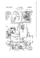
- Figure 1 is a diagrammatic view of one embodiment of the vehicle brake equipment provided by my invention and arranged for installation on a single Vehicle.
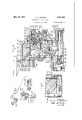
- Figure 2 is a view of the inertia responsive control device employed in the system shown in Fig. 1.
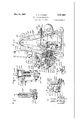
- Figure 3 is a sectional view of a brake valve device which may comprise a part of the system shown in Figure 1.
- Figure 4 is a sectional view of the manual control member employed in the system shown in Figure l, the View being taken substantially along the line 4-4 of Figure 5.
- FIG. 5 is a sectional view of the control member shown in Figure 4, this View being taken substantially along the line 5 5 of Figure 4.
- Figure 6 is a fragmentary sectional View taken substantially along the line 6-6 of Figure 2.
- Figure 7 is a fragmentary sectional view taken substantially along the line 1-1 of Figure 2.
- Figure 8 is a fragmentary sectional view taken substantially along the line 8-8 of Figure 2.
- Figure 9 is a ⁇ fragmentary top plan view of aportion of the inertia responsive control device shown in Figure 2.
- Figure 10 is a fragmentary sectional view of a portion of the control means employed in connection with the inertia responsive control device shown in Figure 2.
- FIG 11 is a perspective view of portions of the control mechanism employed in connection with the inertia responsive control device shown in Figure 2.
- Figure 12 is a diagrammatic development of the manual control means employed in the system shown in Figure 1.
- a brake cylinder I which is supplied with iiuid under pressure from a main reservoir 2, the supply of fluid being regulated by an electroresponsive brake controlling valve device 3, a brake valve device 4, a manual brake control device 5, and an inertia responsive control device 6 which is adjustably variable by means of a manual control element 1, while the fluid flowing to the brake cylinder I is also controlled by the foot valve device 8.
- the manual brake control device which is indicated generally by the reference character 5, comprises a frame 2U which has journaled therein a shaft 2
- the frame also has a lever pivotally mounted thereon by means of a pin 26, the lever 25 having an end portion 21 adapted to be engaged by the cam 23 upon rotation of the shaft by the handle 22, while the other end of the lever 25 has pivotally connected thereto a cable or other suitable operating member 28 the other end of which is connected to an end of the lever 30 of the brake valve device 4.
- the cam 23 is of irregular shape and has a cam surface which increases in radius throughout a portion of its circumference, so that when the cam is rotated, the upper end of the lever is forced to the right as viewed in Figure 1, this portion of the cam corresponding to the service application position of the manual brake control means.
- This cam also has a p ortion of relatively small radius adjacent one side of the first mentioned portion, this portion corresponding to the release portion of the brake control means, while there is a portion of relatively great radius adjacent the other side of the first mentioned cam surface which corresponds to the emergency application position of the brake control means.
- the brake valve device 4 is preferably of the self-lapping type and its construction is best shown in Figure 3 of the drawings. As shown in the drawings the brake valve device 4 comprises a, main casing section 35, a valve section 36, an emergency portion 31, and a pipe bracket section 38, which when assembled together define a pressure chamber 39 which is in constant communication with the brake cylinder by way of the pipe and passage 40.
- the valve section 36 is provided with a valve chamber 43 in which is disposed a supply valve element 44, which is urged toward the seated position by a coil spring 45.
- the valve element 44 controls the supply of fluid under pressure from the main reservoir 2 by way of the pipe and passage 41 and the valve chamber 43.
- the valve section 36 is also provided with a piston chamber in which is mounted a piston 5
- a release valve element 55 Positioned within the chamber 52 is a release valve element 55 which is biased to the unseated position by a coil spring 56, and when the valve element 55 is in its unseated position the Valve chamber 52 is in communication with the atmosphere by way of the passage 51, piston chamber 50 and the passage 58, and when the release valve is in its seated position this communication is cut off.
- is subject on one side to the pressure of the fluid in the pressure chamber 39, and, on the other side, to the pressure of the coil spring 60.
- the tension of the spring may be regulated by a suitable regulating member 6
- This member is provided with a central bore 63 adapted to receive a reduced extension 64 of the piston 5
- a mechanism including a lever 18 which is secured intermediate its ends on the pin 69 to a floating pivot carrier 1
- a stem 15 is pivotally secured to the lower end of the lever 10 and extends into a bore in the end of the supply valve element 44.
- a roller 16 is pivotally mounted on the other end of the lever 1U and is adapted to engage the rounded end of the release valve element 55.
- the springs 45, 56 and 6U are of different values, the spring 45 being of greater resistance than tho spring 56, but being of less resistance than the spring 60.
- the lever 10 will pivot on the axis formed by the stem 15, and the release valve element 55 will be moved to the right against the pressure of the spring 56 so as to close the passages controlled thereby.
- the release valve element 55 On engagement of the release valve element 55 with its seat, and, on further moves proportioned that movement of the floating carrier 1
- a lever 8U which is loosely mounted on a shaft 8
- the spring 58 is of such a value, u and the lever 18 and associated members are so lever and cause it to move the oating pivot carrier 1
- a suitable stop 85 engages a portion of the lever 80 to limit the movementJ of this lever in the counter-clockwise direction.
- the lever Sil which is mounted outside of the main casing section 35, has the operating member 28 secured to one end thereof, and has secured to the other end thereof a spring 86 Which urges the lever 30 in a counter-clockwise direction.
- the emergency portion 3l. of the brake valve device l is provided with a latch block 90 which is secured to a rod 9
- a piston 96 disposed in a chamber 97 and adapted to engage the piston 92 which is secured on the rod 9
- the foot valve device 8 is also incommunication with the chamber 9'! by Way of the safety control pipe
- a piston chamber associated with the inertia responsive control device is in communication with the chamber Si. by way of the passage
- the foot valve device 8 comprises a casing
- 3 is provided which controls the flow of fluid under pressure from the chamber lil to the atmospliere through the passage H4.
- the valve element H3 is held seated by maintaining pressure on the foot pedal H5 which actuates the valve element to the seated position.
- the spring H6 urges the foot pedal out of engagement with the valve element and the pressure of the fluid in the chamber il! may then unseat the Valve H3 and permit the fluid to fiow past the unseated valve to the passage H4 and thence to the atu mosphere.
- the brake controlling valve device 3 comprises a supply magnet valve section
- 20 comprises a casing provided with a valve chamber
- 30 and hav ing disposed therein a double beat valve
- 32 is urged towards an upper seat i355 by a spring
- the double: beat valve is urged to its lower seat
- the release magnet valve section li conip-rises a casing dening a valve chamber IfiE, having constant communication with the brake cylinder by way of the pipe
- 47 is urged toward its seated position by a spring itl and to the unseated position by an electromagnet, (not shown), in the upper part of the casing, which, when energized, moves the valve element
- 23 comprises a casing section defining a valve chamber
- 51 is urged to its seat by a spring
- 22 comprises a casing dening a valve chamber having com* munication with the reservoir 2 by way of a passage
- 60 is a ball valve element
- 63 is urged to the unseated position by a spring
- 10 is such that when a predetermined or selected pressure has been built up in the brake cylinder the pressure will manifest itself on the upper side of the piston
- the construction of the brake controlling valve device is such that for fluid pressures below a predetermined value fluid may flow from the brake valve device 4 to the pip-e 40, and thence through the inshot valve section to the brake cylinder, but that when the pressure in the brake cylinder is built up to a predetermined value further ow of fluid through the inshot valve device is cut off and the supply of fluid 'to the brake cylinder is thereafter controlled by the supply magnet valve section
- the inertia responsive control device- 6 is provided with a housing indicated generally by the reference character
- the control device 6 is adapted to be secured to the vehicle by lugs
- the weighted body IBI swings as a.
- pendulum about the pivot
- 90 may be of any suitable con struction and preferably has a spring associated therewith and normally urging the plunger into engagement with the weighted body
- is preferably constructed so that initial or short movements of the plunger away from the normal position are opposed by a spring
- 94 is positioned in a sleeve member
- 96 is provided with an annular fiange
- member 200 is slidably mounted in the casing section 202 and is urged in a direction toward the weighted body I9! by the spring
- 94 engages a plunger 205 which is reciprocably movable in a guideway formed in the casing section 206 and has a stem 201 over which the spring is fitted.
- may be adjustably varied by moving the plunger 205 towards or away from the weighted body
- Adjustment of the plunger 205 is effected by means of the lever 2
- 4 is provided for the lever 2
- 0 is mounted on the shaft 2
- a lever 220 is also journaled on the shaft 2
- extends through only a portion of the circumference of the hub portion of the lever 220, and, as will be understood, when the lever 220 is turned in a counter-clockwise direction the projecting portion 22
- 9 may be rotated in a counterclockwise. direction without effecting movement of the lever 220.
- the lever 220 has adjacent the other end thereof a slot 222 adapted to receive an operating member which will be described in detail below.
- also has mounted thereon a lever 225 positioned on the opposite of the lever 2 I0 from the lever 220 and which has a hub portion 226 provided with a projection 221 extending throughout a portion only of the circumference of the hub portion and adapted to engage the projecting portion 2
- the projection 221 will engage the projection 2
- the projections 221 and ZIB extend throughout a portion only of the circumference of the hub portions of the members 225 and 2
- 94 may be adjustably varied in either of two ways, one way being by means of the lever 220 and the other way being by means of the lever 225.
- lever 225 has secured in the opening in the end thereof, a connecting link 239 which has its other end pivotally secured to a lever 23
- a spring 238 is also positioned in the cylinder 235 and normally urges the piston 234 upwardly as viewed in Figure 10. Fluid under pressure is supplied to the cylinder 235 by the pipe 249, which communicates with the safety control pipe
- the pressure of the iluid in the chamber 235 urges the piston 234 to its lower position, but upon a reduction in the fluid pressure, the spring 238 urges the piston 234 upwardly and movement of the piston in this direction is transmitted through the members 23
- the manual control element 1 comprises a casing 250 having an arm having one end pivotally secured therein on a suitable pin 252, the arm having secured adjacent the other end thereof a connecting link or rod 254 which has its other end pivotally secured in the slot 222 formed in the end of the lever 228.
- the rod or connecting link 254 may be of any suitable construction, and, as shown in the drawings, is constructed of a plurality of sections which are joined by a turnbuckle 255 by means of which the length of the rod may be adjustably varied. The.
- ; ⁇ and 251 secured thereon by means of which the rod is pivotally secured to the lever 25
- the construction of the clevis 255 which is employed at the lower end of the rod 254 is shown in detail in Figure 7 of the drawings, and as therein illustrated, the clevis has a reduced portion adjacent Vthe end having a bushing ,or sleeve 258 mounted in an aperture adjacent the end of the clevis and adapted to be clamped between the arms of the lever 220 by a bolt 259 so as to be held at a selected point in the slot 222 formed in the lever 22
- the manual control element 1 may be secured in any suitable manner to the vehicle, and, in order to maintain accurate spacing between the ycontrol element 1 and the inertia responsive control device 5, a spacing member 259 is provided which has one end secured to the manual control member 1 and the other end secured to the housing of the inertia responsive control device 6.
- this means comprises a manual operating handle 25
- will be moved in a counter-clockwise direction and will effect a similar movement of the lever 228 which movement will be transmitted to the lever 2
- 85 is connected to one side of the electromagnet associated with the supply magnet valve section
- the other side of the two electromagnets is connected to o ne side of a suitable source of current supply, for example, a battery 218, while the other side of the battery is connected to the movable contact
- the manual brake control means is provided with means to control the pressure of the fluid in the safety control pipe
- the manual control means 5 has a casing section having a chamber
- a double beat valve device 300 is positioned in the chamber
- has a cam 305 secured thereon and engageable with the end of the valve device 300 and operable in certain positions of the cam to move the valve device 300 to the left, as viewed in Figure 1, against the pressure of the spring 303 so that the valve element 306 seats against the seat 301 surrounding the passage leading from the chamber
- is moved away from its seat and fluid is permitted to flow from the safety control pipe
- cam 23 controlling the service application of the brakes and the cam 305 controlling the emergency application of the brakes is shown diagrammatically in Figure 12 of the drawings.
- the cam 23 has a face which is sloping throughout a relatively large portion of the range of movement of the cam and gradually increases from a, point adjacent the left hand side of the diagram, which may be considered the release zone, to a point adjacent the broken line A--A which separates the service application zone from the emergency application zone.
- the cam 23 thereafter has a dwell surface throughout the entire emergency application zone in which zone the cam does not move the lever 21.
- the cam 305 which controls the emergency application of the brakes has a face which is of substantially uniform width throughout the entire service application zone but which slopes very abruptly throughout the emergency application zone during which period it is effective to move the valve device 300. During a service application of the brakes the cam 305 is not operable to move the valve device 300. It is clear, therefore, that at different points in the range of movement of the manual operating handle 22 of the manual brake control means 5, the brakes will be controlled to effect either a service application of the brakes or an emergency application of the brakes depending upon the amount of movement of the manual control member.
- valve device 4 will operate to close the supply valve member 44 to cut off the flow of fluid under pressure to the pressure chamber and therefore to the brake cylinder.
- the flow of fluid to the brake cylinder through the brake controlling valve device 3 may take place through the passage
- fluid under pressure can flow from the pipe 40 to the passage
- the fluid pressure in the brake cylinder has built up to a predetermined value, it will act upon the piston
- will move to the right as viewed in Figs. l and 2, whereupon the movable contact
- the inertia responsive control device 6 together with the brake controlling Valve device 3 will operate to control the degree of application of the brakes so that the rate of retardation of the vehicle will not exceed a predetermined value.
- 94 may be adjustably varied and by changing the adjustment of this spring the amount of force required to move the body
- the system provided by my invention incorporates means to manually change the adjustment on the spring
- the operator can do so by moving the operating handle 25
- the system provided by this invention provides means not only to secure a service application of the brakes, but also an emergency application of the brakes, and on an emergency application of the brakes, the fluid pressure in the brake cylinder is immediately increased to a value which will produce the maximum rate of retardation permitted by the inertia responsive control device 5 irrespective of the rate of retardation to which it has been adjusted by operation of the manual control member l.
- an emergency operation of the brakes is effected if through accident or design pressure is released from the foot pedal II5 of the foot valve device 8.
- the valve element H3 is permitted to move away from the seat formed in the casing l I0 and fluid under pressure is permitted to escape from the chamber III, which is in communication with the control pipe
- a latch 3I0 pivotally secured to the lever 02 and having an end portion adapted to extend into the notch 3II in the latch block 90.
- the latch 3I0 is normally urged to the left, as viewed in Figure 3, by a suitable spring 3I2, and when the lever' 82 is rotated in a clockwise direction the end of the latch 301 projects into the recess 3H to prevent movement of the latch block 90 by the spring
- a braking system adapted for use on vehicles and incorporating an inertia responsive retardation control device which regulates the degree of application of the brakes to control the rate of retardation of the vehicles, and that the inertia responsive retardation controller is constructed so that the rate of retardation which it is effective to produce may be adjustably varied during a service application of the brakes.
- the braking system provided by my invention is constructed so as to provide means to effect not only a service application of the brakes, but also an emergency application of the brakes, and that on an emergency application of the brakes the inertia responsive control device is automatically adjusted to produce th-e maximum rate of retardation of the vehicle permitted by the inertia responsive control device irrespective of the value to which it has been previously adjusted by the manual adjusting means associated therewith.
- the braking system provided by my invention provides means for adjusting the rate of retardation for all rates of retardation less than that provided by any adjustments of the inertia responsive retardation controller, and that this means is directly under the control of the operator of the vehicle through the manual control means and the self-lapping brake valve device employed in the system.
- a vehicle brake apparatus in combination, manually operable means for effecting an application of the brakes, an inertia responsive member movable in response to changes in the speed of the vehicle and operable to control the degree of application of the brakes, whereby the degree of application of the brakes is limited to a degree eifective to produce a predetermined rate r of retardation of the vehicle, and manually operated means independent of the manually operable means for effecting an application of the brakes and operable during an application of the brakes for selectively adjusting the inertia re-- sponslve means whereby the changes in speed to which said inertia responsive member is rcsponsive are selectively varied, and whereby the inertia responsive member may be selectively adjusted to control the degree of application of the brakes to effect different rates oi' retardation of the vehicle,
- inertia responsive means comprising an inertia responsive member movable in response to changes in the speed of the vehicle and operable to control the degree of application of the brakes, whereby the degree of application of the brakes is limited to a degree eiective to p-roduce a predetermined rate of retardation of the vehicle, and manually operated means independent of the manually operable means for effecting service applications of the brakes and operable during an application of the brakes for selectively adjusting the inertia responsive means whereby the changes in the speed to which said inertia rcsponsive member is responsive are selectively varied, and whereby the inertia responsive member may be selectively adjusted to control the degree of application of the brakes to effect different rates of retardation of the vehicle.
- inertia responsive means comprising an inertia responsive member movable in response to changes in the speed of the vehicle and operable to limit the degree of application of the brakes to a maximum degree ci application, whereby the degree of application of the brakes is limited to a degree eiective to produce a predetermined rate of retardation or" the vel'ncle, and manually operated means independent of the manually operable means for effecting service or emergency applications of the brakes and operable during a service application of the brakes to selectively adjust the inertia responsive means whereby said inertia responsive means is conditioned to limit the degree or application ci the brakes to values less than said maximum. degree, and whereby the inertia responsive member may be selectively adjusted to control the degree of application of the brakes to effect different rates of retardation of the vehicle.
- inertia responsive means comprising an inertia responsive member movable in response to changes in the speed of the vehicle and operable to limit the degree of application the brakes to a maximum degree of application, whereby the degree of application or the brakes is limited to a degree effective to produce a predetermined rate of retardation of the vehicle, means independent of the manually operable means for eiiecting applications of the brakes to selectively adjust the inertia responsive means whereby said inertia responsive means is conditioned to limit the degree of application of the brakes to values less than said maximum degree and whereby the inertia responsive member may be selectively adjusted to control the degree of application of the brakes to effect different rates of retardation of the vehicle, and means automatically operable on an emergency application of the brakes to condition the inertia responsive means to permit said maximum degree of application of the brakes irrespective of the adjustment
- inertia responsive means comprising an inertia responsive member movable in response to changes in the speed of the vehicle and operable to limit the degree of application of the brakes to a maximum ⁇ degree of application, whereby the degree of application of the brakes is limited to a degree effective to produce a predetermined rate of retardation or the vehicle, and manually operated means independent of the manually operable means for effecting applications of the brakes to selectively adjust the inertia responsive means whereby said inertia responsive means is conditioned to limit the degree of application of the brakes to values less than said maximum degree and whereby the inertia responsive member may be selectively adjusted to control the degree of application of the brakes to effect different rates of retardation of the vehicle, the inertia responsive means being operable to limit the degree of application of the brakes to values less than said. maximum value only during the service application of the brakes.
- inertia responsive means comprising an inertia responsive member movable in response to changes in the speed of the vehicle and operable to control the degree of application of the brakes, whereby the degree of application of the brakes is limited to a degree eiiective to produce a predetermined rate of retardation of the vehicle, and means for selectively adjusting the inertia responsive means whereby the l'change in the speed to which said inertia responsive member is responsive may be selectively varied and whereby the inertia responsive member may be selectively adjusted to control the degree of application of the brakes to effect different rates of retardation of the vehicle, the means for selectively adjusting the inertia responsive means being operable irrespective of the condition of the brakes or of operation of the manually operable member for effecting an application of the brakes.
- inertia responsive means ccmprising an inertia responsive member movable in response to changes in the speed of the vehicle and operable to control the degree of application of the brakes, whereby the degree of application of the brakes is limited to a degree effective to produce a predetermined rate of retardation of the vehicle, and other manually operable means for selectively adjusting the inertia responsive means whereby the change in the speed to which said inertia responsive member is responsive may be selectively varied, and whereby the inertia responsive member may be selectively adjusted to control the degree of application of the brakes to effect different rates of retardation of the vehicle, the means for selectively adjusting the inertia responsive means being operable during a service application of the brakes.
- inertia responsive means comprising4 an inertia responsive member movable in response to changes in the speed of the vehicle and operable to control the degree of application of the brakes, whereby the degree of application ci the brakes is limited to a degree eiiective to produce a predetermined rate of retardation of the vehicle, and other manually operable means for selectively adjusting the inertia responsive means whereby the change in the speed to which said inertia responsive member is responsive may be selectively varied and whereby the inertia responsive member may be selectively adjusted to control the degree of application of the brakes to eiiect different rates of retardation of the vehicle, safety means for effecting an emergency application of the brakes, means responsive to manually applied pressure of an operator ier preventing operation of said safety means and providing for operation thereof upon release oi said manually applied pressure, and means automatically operable on an emergency application
- inertia responsive means comprising an inertia responsive member movable in response to changes in the speed of the vehicle and operable to control the degree of application ol the brakes, whereby the degree of application of the brakes is limited to a degree effective to produce a predetermined rate of retardation of the vehicle, and manually operated means independent ci the manually operable means for eiiecting an application of the brakes and operable during an application of the brakes for selectively adjusting the inertia responsive means whereby the change in speed to which said inertia responsive member is responsive may be selectively varied and whereby the inertia responsive member may be selectively adjusted to control the degree of application of the brakes to effect different rates of retardation of the vehicle, said manually operable means being operable to ellect different degrees of application ol the brakes, whereby the degree of application of the brakes for values less than the degree of application determined
- a vehicle brake apparatus in combination, manually operable means for effecting an application of the brakes, an inertia responsive member movable in response to changes in the speed of the vehicle and operable to control the degree of application of the brakes, whereby the degree of application of the brakes is limited to a degree effective to produce a predetermined rate of retardation of the vehicle, and means for selectively adjusting the inertia responsive means whereby the change in the speed to which said inertia responsive member is responsive may be selectively varied and whereby the inertia responsive member may be selectively adjusted to control the degree or application of the brakes to effect diii'erent rates oi retardation of the vehcle, the means for selectively adjusting the inertia responsive means being operable irrespective of the condition of the brakes or of operation of the manually operable means for effecting an application oi' the brakes.
- a brake cylinder manually operable means for controlling the supply and release of fluid under pressure to and from the brake cylinder, a cut-off valve controlling the supply of fluid under pressure to the brake cylinder, a ⁇ release valve controlling the release of fluid from the brake cylinder, inertia responsive means comprising an inertia responsive member movable in response to changes in the rate of speed of the vehicle, and operable in response to one rate of change oi' speed of the vehicle to control the cut-off valve to out off the supply of fluid to the brake cylinder and operable in response to a greater rate of change of speed of the vehicle to control the release valve to release fluid under pressure from the brake cylinder, and manually operated means operable during an application of the brakes to adjustably vary the inertia responsive means whereby the change in the rate of speed of the vehicle which is effective to move the inertia responsive member to control the cut-off valve may be adjustably varied, the difference between the rate of change of speed effective to move the
- a brak-e cylinder' controlling the supply of fluid under pressure to the brake cylinder, a release valve controlling the release oll fluid from the brake cylinder'
- inertia responsive means comprising an inertia responsive member movable in response to changes in the rate ol' speed of the vehicle, and operable in response to one rate of change oi speed oi the vehicle to control the cut-off valve to cut oil the supply ci' fluid to the brake cylinder, and operable in rcsporrc to a greater rate of change of speed the vehicle to control the release valve to release fluid under pressure from the brake cylinder, operable during an application of the brakes to adjustu ably vary the inertia responsive means w ereby the change in the rate of speed of the vehicle which is effective to move the inertia responsive member to control the cutpfi' valve may adjustably vari-ed, and manually operable means for controlling the pressure ol fluid
- a brake cylinder manually operable mea 'i for controlling the pressure ci fluid in the brake cylinder, a cut-olf valve controlling the supply of fluid under pressure te the brake cylinder, a release valve controlling the release of iuid under pressure from the brake cylinder, inertia responsive means comprising a member movable in response to changes in the rate o speed of the vehicle and operable in response to one rato ol" change in the speed of the vehicle to control the cut-oli valve to cut oil?
- the supply oi duid to the brake cylinder and operable in response to a greater rate of change in the speed ol the vehicle to control the release valve to effect a rclea e ol uid under pressure from the brake cy mr, whereby the degree of application of the brakes is limited to a degree effective to produce a predetermined rate of change in the speed oi the vehicle, and means independnt of the mani.
- a brake cylinder In combination, a brake cylinder, manually operable means for controlling the pressure ol the fluid in the brake cylinder, said manually operable means Ii l.
- a cut-oli" valve controlling the supply of iluid under pressure to the brake cylinder, a release valve controlling the release of fluid under pressure from the brake cylinder
- inertia responsive means comprising a member movable in response to changes in the speed of the vehicle and operable in response to one rate of change in the speed of the vehicle to control the cut-ofi" valve to cut oil the supply of fluid to the brake cylinder and operable in response to a greater rate of change in the speed of the vehicle to control the release valve to effect a release of iluid under pressure from the brake cylinder, whereby the degree of application oi the brakes is limited to a degree effective to produce a predetermined rate of retardation of the vehicle, the inertia responsive means being operable to limit the degree of application of the brakes to a maximum degree of application, means independent of the manually operable means for controlling the pressure of the uid in the brake cylinder and operable during an
- inertia responsive means comprising an inertia responsive member movable in response to changes in the speed of the vehicle and operable to control the degree of application of the brakes, whereby the degree of application of the brakes is limited to a degree effective to produce a predetermined rate of retardation of the vehicle, and means operable independently of the manually operable means for eiecting applications of the brakes for selectively adjusting the inertia responsive means whereby the change in the speed to which said inertia responsive member is responsive may be selectively varied, and whereby the inertia responsive member may be selectively adjusted to control the degree of application of the brakes to effect different rates of retardation of the vehicle, the means for adjusting the inertia responsive means comprising a member movable between spaced points, manually operable means for moving said member between said spaced points, and means automatically operable on an emergency application of the
- inertia responsive means comprising an inertia responsive member movable in response to changes in the speed of the vehicle and operable to control the degree of application of the brakes whereby the degree of application of the brakes is limited to a degree effective to produce a predetermined rate of retardation of the Vehicle and means for selectively adjusting the inertia responsive means, whereby the change in the speed to which said inertia responsive member is responsive may be selectively Varied and whereby the inertia responsive member may be selectively adjusted to control the degree or" application of the brakes to effect different rates of retardation on the vehicle, the means for adjusting the inertia responsive means comprising a member movable between spaced points, said means being normally urged toward one of the said spaced points, manually operable means for moving said member toward the other of said spaced points, and means automatically operable on an emergency application of the brakes
- an inertia responsive device adapted to control the application of the brakes on a vehicle, a member having a normal position, said f said normal position responsive to inertia, and
- manually operable means operable during an application of the brakes to adjustably vary one of said resilient means whereby the force of inertia required to move said inertia responsive member against said resilient means may be adjustably varied.
- a pendulum pivotally supported on an axis, said pendulum having a normal position, a plurality of springs yieldingly opposing movement of said pendulum away from said normal position, the pendulum being movable away from said normal position responsive to inertia, and manually operable means operable during an application of the brakes to adjustably vary the force exerted by one of said springs on said pendulum whereby the force of inertia required to move said pendulum may be adjustably varied.
- a pendulum pivotally supported on an axis, said pendulum having a normal position, a spring associated with said pendulum and opposing movement of said pendulum away from the normal position in one direction, and manually operable means operable during an application of the brakes to adjustably vary the force exerted by said spring on said pendulum whereby the force of inertia required to move said pendulum against said spring may be adjustably varied
- the means for adjustably varying the force exerted by said spring on said pendulum comprising a member movable between spaced points, and manually operable means to eect movement of said member to one of said spaced points.
- a pendulum pivotally Supported on an axis, said pendulum having a normal position, a spring associated with said pendulum. and opposing movement of said pendulum away from the normal position in one direction, and manually operable means to adjustably vary the force exerted by said spring on said pendulum whereby the force of inertia required to move said pendulum against said spring may be adjustably varied,
- the means for adjustably varying the force exerted by said spring on said pendulum comprising a member movable between spaced points, said member being urged to one of said spaced points by said spring, and manually operable means to effect movement of said member to the other of said spaced points.
- a pendulum pivotally supported on an axis, said pendulum having a normal position, a spring associated with said pendulum and opposing movement of said pendulum away from the normal position in one direction, means to adjustably vary the force exerted by said spring on s-aid pendulum whereby the force of inertia required to move said pendulum against said spring may be adjustably varied,
- the means for adjustably varying the force exerted by said spring on said pendulum comprising a member movable between spaced points, said member being urged to one of said spaced points by said spring, and a plurality of means to effect movement oi said member toward the other of said spaced points, each of said means being operable to effect movements of said member toward said last named spaced point irrespective of the position to which said member has been adjusted by other of said means.
- an inertia responsive device adapted to control the application of the brakes on a vehicle, -a pendulum pivotally supported on an axis, said pendulum having a normal position, a spring associated with said pendulum and opposing movement of said pendulum away from said normal position in one direction, a second spring associated with said pendulum and opposing movement of said pendulum away from the normal position beyond a zone adjacent said normal position, and manually operable means operable during an application of the brakes to adjustably vary the force exerted by said first named spring on said pendulum whereby the force of inertia required to move said pendulum may be adjustably varied, and whereby the additional force required to move said pendulum outside said zone adjacent the normal position is substantially constant irrespective of the -adjustment of the first spring.
- inertia responsive means comprising an inertia responsive member movable in response to changes in the speed of the vehicle and oper-able to control the degree of application of the brakes, whereby the degree of application of the brakes is limited to a degree eiective to produce a predetermined rate of retardation of the vehicle
- means independent of the manually operable means for effecting a service application of the brakes for selectively adjusting the inertia responsive means whereby the changes in the rate of speed to which said inertia responsive member is responsive are selectively varied, and whereby the inertia responsive member may be selectively adjusted to control the degree of application of the brakes to effect dierent rates of retardation of the vehicle
- a safety control pipe and means responsive to a reduction of the pressure of the fluid in said safety control pipe and operable to condition said inertia responsive means to permit a high degree ol application of the brakes
- a brake cylinder In a brake equipment for vehicles, in combination, a brake cylinder, manually operable brake controlling means for controlling the supply of fluid under pressure to said brake cylinder, a retardation controller responsive to the rate of deceleration of the vehicle for regulating the degree of fluid pressure in said brake cylinder, said retardation controller comprising an inertia responsive element and biasing means for opposing movement of said inertia responsive element, and manually operable means independent of the brake controlling means and operable during an application of the brakes for varying the force exerted on said inertia responsive element by said biasing means.
- braking means in combination, braking means, a manually operable member for effecting an application of the braking means and for varying the degree of application of the braking means between predetermined limits, retardation control means for con- "i trolling the braking means, said retardation control means comprising relatively movable elements operable in response to a predetermined degree of movement relative to each other for limiting the degree of application of the braking means to values less than the maximum which may be capturedd by the manually operable member, one of said elements being movable responsive to retardation of the vehicle, one of said elements having adjusting means associated there- 'fwith whereby the rate of retardation of the vehicle effective to produce the predetermined degree of relative movement between said elements may be adjustably varied, cam actuated means for varying said adjusting means under service conditions, and manually controlled means for operating said cam means.
- a member movable responsive to inertia said member having a normal position, a spring associated with said member and opposing movement of said member away from the normal position, a second spring associated with said member and opposing movement thereof away from the normal position beyond a Zone adjacent the normal position, and manually operable means operable during an application oi the brakes to adjustably vary the force exerted by said first named spring on said member whereby the force of inertia required to move said member from the normal position may be adjustably varied, and whereby the additional force required to move said member outside said zone adjacent the normal position is substantially constant irrespective of the adjustment of the iirst named spring.
Landscapes
- Engineering & Computer Science (AREA)
- Transportation (AREA)
- Mechanical Engineering (AREA)
- Regulating Braking Force (AREA)
- Braking Arrangements (AREA)
Description
May 25, 1937. c. c. FARMER RETARDATION CONTROLLER 5 Sheets-Sheet 1 Filed Jan. 9, 1935 May 25, 1937. C. c, FARMER RETARDATION CONTROLLER Filed Jan. 9, 1935 3 Sheets-Sheet 2 @QN @NN QNN \NN QN o L wim www l SN Qmm M N huw ,SN N
.Q N www. .N N @mf INVENTOR CLYDE C. FAR MER Q//.d/
ATTORN Y May 25, 1937. C. Q FARMER f 2,081,663
RETARDAT ION CONTROLLER Filed Jan. 9, l935 l 3 Sheets-Sheet 5 5 k Q n 1Q w INVENTOR CLYDE C. FARMER A TTORNE Y Patented May 25, 1937 UNITED STATES PATENT GFFICE RETARDATION CONTROLLER Application January 9, 1935, Serial No. 971
26 Claims.
This invention relates to vehicle brakes and more particularly to means for controlling the degree of application of the brakes to automatcally regulate the rate of retardation of the vehicle.
1t is well known that for a given braking pressure friction type brakes are less effective in retarding the vehicle at high speeds than at low speeds because the coefficient of friction between the rubbing parts is lower at high speeds than at low speeds. In order to bring a vehicle to a stop quickly it has been the usual practice for an operator to apply the brakes with a high -degree of braking pressure at high speeds, and, as the speed o the vehicle decreases, to so operate the brakes as to cause the braking pressure to decrease in such a man-ner that the vehicle is brought to a stop quickly and smoothly without dangerous shock or sliding of the wheels. Various devices have been developed to automatically accomplish such varying of the braking pressure in response to the movement of an element so that the braking pressure is varied to effect a predetermined rate of retardation of the vehicle. The retardation control devices heretofore used, however, have usually been constructed in such a manner that they were operable only for a single rate of retardation. This was not satisfactory for all phases of operation and it is desirable to have means to adjustably vary the rates of retardation to which the retardation controller is responsive.
It is the principal object of my invention, therefore, to provide retardation control apparatus adapted for use on a vehicle such as a railway train which apparatus may be adjustably controlled to effect diiferent degrees of application of the brakes whereby different rates of retardation of the vehicle are automatically secured.
Another object of my invention is to provide a retardation control device in whichthe rate of retardation to which the device is responsive is adjustably variable, and which has a maximum rate of retardation to which it is automatically adjusted on emergency application of the brakes irrespective of the rate of retardation to which it has been previously adjusted.
A further object of the invention is to provide a vehicle brake equipment adapted to permit either a service application or an emergency application of the brakes and having associated therewith automatically operable retardation control means Which is operable to automatically control the degree of application of the brakes to effect a predetermined rate of retardation of the vehicle.
Another object of the invention is to provide a vehicle braking equipment adapted to permit either a service. application or an emergency apiplication oi the brakes and having retardation control means associated therewith and operable to control the degree of application of the brakesto effect a uniform rate of retardation of the vehicle and having manually operable means to adjustably vary the rate of retardation during a service application of the brakes.
A further object of the invention is to provide a vehicle braking equipment adapted to permit a service application or an emergency application of the brakes and having retardation control means associated therewith to automatically control the degree of application of the brakes to eiect a substantially uniform rate of retardation of the vehicle, and having safety means associated therewith for effecting an emergency application of the brakes, which means is also effective to adjust the retardation control means to its maximum value irrespective of the value to which it has been previously adjusted.
Another object of my invention is to provide an inertia responsive control device incorporating manually operable adjusting means by means of which the force of inertia required to effect movement of the inertia responsive member employed in the control device to the operative position in its range of movement may be adjustably Varied.
Other objects of the invention and features of novelty will be apparent from the following description taken in connection with the accompanying drawings in which:
Figure 1 is a diagrammatic view of one embodiment of the vehicle brake equipment provided by my invention and arranged for installation on a single Vehicle.
Figure 2 is a view of the inertia responsive control device employed in the system shown in Fig. 1.
Figure 3 is a sectional view of a brake valve device which may comprise a part of the system shown in Figure 1.
Figure 4 is a sectional view of the manual control member employed in the system shown in Figure l, the View being taken substantially along the line 4-4 of Figure 5.
Figure 5 is a sectional view of the control member shown in Figure 4, this View being taken substantially along the line 5 5 of Figure 4.
Figure 6 is a fragmentary sectional View taken substantially along the line 6-6 of Figure 2.
Figure 7 is a fragmentary sectional view taken substantially along the line 1-1 of Figure 2.
Figure 8 is a fragmentary sectional view taken substantially along the line 8-8 of Figure 2.
Figure 9 is a` fragmentary top plan view of aportion of the inertia responsive control device shown in Figure 2.
Figure 10 is a fragmentary sectional view of a portion of the control means employed in connection with the inertia responsive control device shown in Figure 2.
Figure 11 is a perspective view of portions of the control mechanism employed in connection with the inertia responsive control device shown in Figure 2.
Figure 12 is a diagrammatic development of the manual control means employed in the system shown in Figure 1.
Referring to the drawings and more particularly to Figure l thereof the embodiment of the invention therein illustrated comprises a brake cylinder I which is supplied with iiuid under pressure from a main reservoir 2, the supply of fluid being regulated by an electroresponsive brake controlling valve device 3, a brake valve device 4, a manual brake control device 5, and an inertia responsive control device 6 which is adjustably variable by means of a manual control element 1, while the fluid flowing to the brake cylinder I is also controlled by the foot valve device 8.
Considering now in detail the construction of each of the elements employed in the brake system illustrated in Figure 1l the manual brake control device which is indicated generally by the reference character 5, comprises a frame 2U which has journaled therein a shaft 2| having secured on its upper end an operating handle 22, and having secured adjacent the lower end thereof, a suitable cam element 23. The frame also has a lever pivotally mounted thereon by means of a pin 26, the lever 25 having an end portion 21 adapted to be engaged by the cam 23 upon rotation of the shaft by the handle 22, while the other end of the lever 25 has pivotally connected thereto a cable or other suitable operating member 28 the other end of which is connected to an end of the lever 30 of the brake valve device 4. The cam 23 is of irregular shape and has a cam surface which increases in radius throughout a portion of its circumference, so that when the cam is rotated, the upper end of the lever is forced to the right as viewed in Figure 1, this portion of the cam corresponding to the service application position of the manual brake control means. This cam also has a p ortion of relatively small radius adjacent one side of the first mentioned portion, this portion corresponding to the release portion of the brake control means, while there is a portion of relatively great radius adjacent the other side of the first mentioned cam surface which corresponds to the emergency application position of the brake control means.
The brake valve device 4 is preferably of the self-lapping type and its construction is best shown in Figure 3 of the drawings. As shown in the drawings the brake valve device 4 comprises a, main casing section 35, a valve section 36, an emergency portion 31, and a pipe bracket section 38, which when assembled together define a pressure chamber 39 which is in constant communication with the brake cylinder by way of the pipe and passage 40.
The valve section 36 is provided with a valve chamber 43 in which is disposed a supply valve element 44, which is urged toward the seated position by a coil spring 45. The valve element 44 controls the supply of fluid under pressure from the main reservoir 2 by way of the pipe and passage 41 and the valve chamber 43.
' The valve section 36 is also provided with a piston chamber in which is mounted a piston 5| which is provided with a valve chamber 52 which is in communication with the pressure chamber 39 by way of a passage 53.
Positioned within the chamber 52 is a release valve element 55 which is biased to the unseated position by a coil spring 56, and when the valve element 55 is in its unseated position the Valve chamber 52 is in communication with the atmosphere by way of the passage 51, piston chamber 50 and the passage 58, and when the release valve is in its seated position this communication is cut off.
The piston 5| is subject on one side to the pressure of the fluid in the pressure chamber 39, and, on the other side, to the pressure of the coil spring 60. The tension of the spring may be regulated by a suitable regulating member 6|. This member is provided with a central bore 63 adapted to receive a reduced extension 64 of the piston 5|, while a regulating screw 65 is adapted to extend into the bore 63 to limit the amount of movement of the piston 5| to the right as viewed in Figure 3.
For actuating the supply Valve element 44 to its application position, and the release valve 55 t0` the seated position, there is provided a mechanism including a lever 18 which is secured intermediate its ends on the pin 69 to a floating pivot carrier 1| which is slidably mounted in a bore 12 in the valve section 36 and in a guiding lug 13 formed integral with the main casing section 35.
A stem 15 is pivotally secured to the lower end of the lever 10 and extends into a bore in the end of the supply valve element 44. A roller 16 is pivotally mounted on the other end of the lever 1U and is adapted to engage the rounded end of the release valve element 55.
The springs 45, 56 and 6U are of different values, the spring 45 being of greater resistance than tho spring 56, but being of less resistance than the spring 60. When the iioating pivot carrier 1| is moved to the right, as viewed in Figures 3 and 4,
the lever 10 will pivot on the axis formed by the stem 15, and the release valve element 55 will be moved to the right against the pressure of the spring 56 so as to close the passages controlled thereby. On engagement of the release valve element 55 with its seat, and, on further moves proportioned that movement of the floating carrier 1| does not affect the position of the piston 5|.
For actuating the floating pivot carrier 1| there is provided a lever 8U which is loosely mounted on a shaft 8|, which is journaled in the main casing section 35 and which projects through the casing section Wall and has the lever 30 secured to the outer end thereof. is rigidly secured on the shaft 8| and is provided with a lug or projecting portion 83 which overlies a portion of the lever 80 so that when the lever 82 is moved in a clockwise direction, as viewed in Figure 3, the lug 83 will engage the The spring 58 is of such a value, u and the lever 18 and associated members are so lever and cause it to move the oating pivot carrier 1|. A suitable stop 85 engages a portion of the lever 80 to limit the movementJ of this lever in the counter-clockwise direction. The lever Sil, which is mounted outside of the main casing section 35, has the operating member 28 secured to one end thereof, and has secured to the other end thereof a spring 86 Which urges the lever 30 in a counter-clockwise direction.
As'will be seen in Figure 1, when the handle 22 is operated so as to cause the cam 23 to engage the end 21 of the lever 25, the cable 28 will be urged to the left causing the lever 30 to be mo-Ved in a clockwise direction which will effect movement of the floating pivot carrier 1| so as to cause the release valve element 55 to move to the closed position, and thereafter to cause the supply valve element 44 to be moved tc the open position, thus allowing fluid under pressure to flow from the main reservoir 2 through the pipe and passage 4l to the pressure chamber 39. When the pressure in the chamber 39 builds up to a suicient value the piston 5| is moved to the right against the pressure of the spring 6|). When the piston 5| has moved to the right a sufficient distance the lever Hl will pivot on the pin 69, being urged in a clockwise direction by the spring 45 pressing on the supply valve member 44, whiley the roller 'I5 is held only by the spring 56, which, as pointed out above, is of a smaller value than the spring 45. The supply valve member, therefore, will be moved to its seated position, thereby cutting oil the flow of fluid under pressure to the pressure chamber 39 and the supply of huid will thus be lapped. It will be seen that the farther the oating pivot carrier 'il is moved to the right the greater will be the pressure required to actuate the piston 5i to the right against the pressure of the spring 5i) to effect a seating of the supply valve element M. As the movement of the floating pivot carrier l| is governed by movement of the control handle E2 oi the control device 5 it is clear that the pressure at which the valve mechanism laps the supply of fluid to the pressure chamber 39 corresponds to the degree of movement of the handle 22.
When the handle 22 is moved to the release position the oating pivot carrier il will be per- .mitted to move to the left as viewed in Figure 3, so that the supply valve element 44 will be seated, and the release valve element 55 will be unseated by the action or the spring 55, whereupon iiuid under pressure will be released from the pressure chamber 35i, and hence from the brake cylinder l, to the atmosphere.
The emergency portion 3l. of the brake valve device l is provided with a latch block 90 which is secured to a rod 9|, which has mounted on one end thereof a piston 92 and which has the other end thereof slidably positioned in a bore 93 in a guiding element 9d. For operating the rod 9| and the latch block to the right there is provided a piston 96 disposed in a chamber 97 and adapted to engage the piston 92 which is secured on the rod 9|. Fluid under pressure is supplied to the chamber 3l from the main reservoir E by means oi the pipe lili?, chambers |9| and |92, safety control pipe |63 and the passage h'lfl. As long as fluid under pressure is supplied to the chamber Sl at a pressure substantially equal to that in the main reservoir 2 the piston 95 will maintain the latch block GB and rod 3| in the position to the right as shown in Figure 3, but when uid is released from the chamber 91 the piston 96 is permitted to move to the left and a spring |06 then moves the latch block 9|! to the left so that the upper portion of the latch block engages the lower end of the lever 89 to move it in a clockwise direction. The rod si is also urged to the left by pressure of the fluid in the pressure chamber 39 acting on the piston 92, which also serves to prevent the escape of the iluid under pressure from the chamber 39. An atmospheric vent passage |97 opens to the chamber intermediate the pistons 92 and 96 so that the chamber is maintained at atmospheric pressure.
The foot valve device 8 is also incommunication with the chamber 9'! by Way of the safety control pipe |03 and the passage |94. In addition a piston chamber associated with the inertia responsive control device is in communication with the chamber Si. by way of the passage |94, and the safety control pipe |63. The purpose of this will appear later.
The foot valve device 8 comprises a casing |||l in which is formed a chamber which is in communication with the safety control pipe |93 by way of a pipe H2. A valve element ||3 is provided which controls the flow of fluid under pressure from the chamber lil to the atmospliere through the passage H4. The valve element H3 is held seated by maintaining pressure on the foot pedal H5 which actuates the valve element to the seated position. When pressure on the foot pedal ||5 is released the spring H6 urges the foot pedal out of engagement with the valve element and the pressure of the fluid in the chamber il! may then unseat the Valve H3 and permit the fluid to fiow past the unseated valve to the passage H4 and thence to the atu mosphere.
The brake controlling valve device 3 comprises a supply magnet valve section |20, a release magnet valve section 2i, an inshot valve section |22, and a safety valve device |23 which is se cured to the release magnet valve Sectio-n |2i.
The supply magnet valve section |20 comprises a casing provided with a valve chamber |25 havu ing constant communication with the brake cylinder by a passage |26 and pipe |30 and hav= ing disposed therein a double beat valve |32 secured to a valve stem |33. The double beat Valve |32 is urged towards an upper seat i355 by a spring |35 operating on the lower end of the valve stem |33 so that when the valve is in posim tion against 'the upper seat iiuid under pressure may ilow from the pipe Si? leading i'rom brake valve device d to the passage ll, to the chamber |38, and thence through the open valve seat |33 to the passage 25, and to the brake cylinder. The double: beat valve is urged to its lower seat |39 by an electrwmagnet, (not shown), in the upper portion of the casing, which, when energized, forces valve downwardly to its lower seated position thereby cutting off the supw ly of fluid under pressure to the brake cylinder I.
The release magnet valve section li conip-rises a casing dening a valve chamber IfiE, having constant communication with the brake cylinder by way of the pipe |39 and a passage Hit, and having disposed therein a valve element lill' which cooperates with a seat ht to control the release of fluid under pressure from the brake cylinder l to the atmosphere by way of chamber |49, passage |53 and the safety Valve device |23. The valve element |47 is urged toward its seated position by a spring itl and to the unseated position by an electromagnet, (not shown), in the upper part of the casing, which, when energized, moves the valve element |41 downwardly away from the seat |48.
The safety valve device |23 comprises a casing section defining a valve chamber |56 in which is positioned a suitable valve element, such as a ball |51, which cooperates with a seat formed in the casing section |2| to control the release of fluid under pressure from the chamber |49. The ball |51 is urged to its seat by a spring |58 and the safety valve device acts in a well known manner to prevent the entire release of fluid under pressure from the brake cylinder.
The inshot valve section |22 comprises a casing dening a valve chamber having com* munication with the reservoir 2 by way of a passage |6| which communicates with the pipe 40 and the brake valve device 1|. Positioned in the valve chamber |60 is a ball valve element |63 which is engaged by a stein |64 associated with a piston |65 mounted in a chamber |61 having constant communication with the atmosphere by way of a passage |68. The ball valve |63 is urged to the unseated position by a spring |10 acting upon the piston |65, and when the ball valve |63 is in the unseated position, fluid under pressure may flow from the chamber |60 to the brake cylinder -by Way of passage |1| and the pipe |30.
The resistance of the spring |10 is such that when a predetermined or selected pressure has been built up in the brake cylinder the pressure will manifest itself on the upper side of the piston |65 to urge the piston downwardly against the compression spring |10 until the ball valve |63 is seated, whereupon the flow of fluid under pressure from the chamber |50 to the brake cylinder is cut off. It will be seen, therefore, that the construction of the brake controlling valve device is such that for fluid pressures below a predetermined value fluid may flow from the brake valve device 4 to the pip-e 40, and thence through the inshot valve section to the brake cylinder, but that when the pressure in the brake cylinder is built up to a predetermined value further ow of fluid through the inshot valve device is cut off and the supply of fluid 'to the brake cylinder is thereafter controlled by the supply magnet valve section |20.
The inertia responsive control device- 6 is provided With a housing indicated generally by the reference character |80, which encloses a weighted body |8| which suspended from a pivot |82 and carries a. contact |83 adapted to engage the contacts |85 and |86, which are sup ported by the housing and insulated therefrom. The control device 6 is adapted to be secured to the vehicle by lugs |81 in such a manner that when the vehicle is on a true horizontal track or roadway the weighted body |8| is in a balanced or normal position with the contacts |85 and |86 out of engagement with the contact |83. The weighted body IBI swings as a. pendulum about the pivot |82 and is normally held in the normal position by the opposing, spring-pressed plungers and I9| and is adapted to be moved in opposition to one of those plungers when acted upon yby force of inertia as during a change in the rate of speed of the vehicle.
The plunger |90 may be of any suitable con struction and preferably has a spring associated therewith and normally urging the plunger into engagement with the weighted body |8| and opposing the movement of this body to the right as viewed in Figure 2.
The plunger |9| is preferably constructed so that initial or short movements of the plunger away from the normal position are opposed by a spring |94, While larger movements are opposed by a` spring in addition to the spring |94. The spring |94 is positioned in a sleeve member |90 intertting with the plunger |9| and having shims |98 disposed therebetween for the purpose of adjusting contact between the plunger |9| and the weighted body |8|. The sleeve member |96 is provided with an annular fiange |99 which is engageable with a radially inwardly extending flange on the member 200 and with the end portion of the member 20| which is secured in the member 200, and, as shown in drawings, a limited amount of movement is permitted the sleeve |96 between the members 200 and 20|. The
The outer end of the spring |94 engages a plunger 205 which is reciprocably movable in a guideway formed in the casing section 206 and has a stem 201 over which the spring is fitted. The pressure which the spring |94 exerts on the plunger |9| may be adjustably varied by moving the plunger 205 towards or away from the weighted body |8|.
Adjustment of the plunger 205 is effected by means of the lever 2| 0 which is mounted on a shaft 2|! which is supported on bearings formed in the casing section 206 and which has a roller 2|2 mounted in the end thereof and engageable with the plunger 205.
An adjusting screw 2 |4 is provided for the lever 2|0 and is engageable. with a portion of the casing section 206 to limit the inward movement of the arm or lever 2|0 and thereby control the degree to which the spring |94 may be compressed.
The lever 2|0 is mounted on the shaft 2| and its hub portion 2|5 is provided with projecting portions 2|6 and 2|1 which extend throughout a portion only of the circumference of the hub1 as is best shown in Figure il of the drawings. A lever 220 is also journaled on the shaft 2|| and its hub portion is provided with a projecting portion 22| which is adapted to engage the project ing portion 2|1 on the lever 2|0 when the lever 220 is oscillated. The projecting portion 22| extends through only a portion of the circumference of the hub portion of the lever 220, and, as will be understood, when the lever 220 is turned in a counter-clockwise direction the projecting portion 22| will engage the projecting portion 2|1 and cause the lever 2|0 to be rotated in a counter-clockwise direction. However, as the projecting portions 2|6 and 22| each extend through only a small portion of the circumference of the hub portions of these members, the lever 2|9 may be rotated in a counterclockwise. direction without effecting movement of the lever 220. The lever 220 has adjacent the other end thereof a slot 222 adapted to receive an operating member which will be described in detail below.
The shaft 2|| also has mounted thereon a lever 225 positioned on the opposite of the lever 2 I0 from the lever 220 and which has a hub portion 226 provided with a projection 221 extending throughout a portion only of the circumference of the hub portion and adapted to engage the projecting portion 2|6 on the lever 2|0.
As will be understood when the lever 225 is rotated in a counter-clockwise direction the projection 221 will engage the projection 2|6 to cause the lever 2|0 to be moved in a counterclockwise direction. As the projections 221 and ZIB extend throughout a portion only of the circumference of the hub portions of the members 225 and 2|9, respectively, the lever 2|9 may be. rotated in a counter-clockwise direction relative to the lever 225 without effecting movement of the lever 225. It is clear, therefore, that the lever 2|0 may be moved by either the lever 22!! or the lever 225 to effect an increase in the degree of compression of the spring |94 without changing the position of the other lever and irrespective of the position to which the lever 2li) may have been moved by either of the levers 220 or 225.
The degree of compression of the spring |94, therefore, may be adjustably varied in either of two ways, one way being by means of the lever 220 and the other way being by means of the lever 225.
As is best shown in Figure of the drawings the. lever 225 has secured in the opening in the end thereof, a connecting link 239 which has its other end pivotally secured to a lever 23| which is pivotally mounted intermediate its ends on a suitable pin 232, and has pivotally secured to its other end through the medium of the link 233, a piston 234 which is disposed in a cylinder 235 formed in a portion of the casing section 296. A spring 238 is also positioned in the cylinder 235 and normally urges the piston 234 upwardly as viewed in Figure 10. Fluid under pressure is supplied to the cylinder 235 by the pipe 249, which communicates with the safety control pipe |93 and thereby with the emergency portion of the brake control device 4. The pressure of the iluid in the chamber 235 urges the piston 234 to its lower position, but upon a reduction in the fluid pressure, the spring 238 urges the piston 234 upwardly and movement of the piston in this direction is transmitted through the members 23| and 239 to the lever 225 and thereby to the lever 2|@ to effect an increase in the pressure on the spring |94 to the maximum permitted by the adjusting screw 2| 4.
'Ihe lever 220 has associated therewith means to manually vary the pressure on the spring |94, and as shown in the drawings, this means comprises a manual control element indicated generally by the reference character 1. As shown in the drawings, the manual control element 1 comprises a casing 250 having an arm having one end pivotally secured therein on a suitable pin 252, the arm having secured adjacent the other end thereof a connecting link or rod 254 which has its other end pivotally secured in the slot 222 formed in the end of the lever 228. The rod or connecting link 254 may be of any suitable construction, and, as shown in the drawings, is constructed of a plurality of sections which are joined by a turnbuckle 255 by means of which the length of the rod may be adjustably varied. The. ends of the rod have suitable clevises 25|;` and 251 secured thereon by means of which the rod is pivotally secured to the lever 25| at one end, and to the lever 220 at the other end. The construction of the clevis 255 which is employed at the lower end of the rod 254 is shown in detail in Figure 7 of the drawings, and as therein illustrated, the clevis has a reduced portion adjacent Vthe end having a bushing ,or sleeve 258 mounted in an aperture adjacent the end of the clevis and adapted to be clamped between the arms of the lever 220 by a bolt 259 so as to be held at a selected point in the slot 222 formed in the lever 22|).
The manual control element 1 may be secured in any suitable manner to the vehicle, and, in order to maintain accurate spacing between the ycontrol element 1 and the inertia responsive control device 5, a spacing member 259 is provided which has one end secured to the manual control member 1 and the other end secured to the housing of the inertia responsive control device 6.
Means is provided to control movement of the rod 254, and shown in the drawings, this means comprises a manual operating handle 25| which is mounted en a shaft 262 journaled in the casing section 289, and which has secured on the opposite end a cam 255 which is engageable with a projection 266 on the lever 25|. As will be understood, when the handle is rotated in a counter-clockwise direction as viewed in Figure 4 of the drawings, the lever 25| will be moved in a counter-clockwise direction and will effect a similar movement of the lever 228 which movement will be transmitted to the lever 2|() to effect an increase in the pressure on the spring |94.
As initial movement of the body |8| is opposed by the spring |94 and subsequent movement of the body is opposed by the spring |95 in addition to the spring |94, it will be apparent that a relatively small force of inertia will move the body against the spring |94 and thereafter a somewhat larger force of inertia is required to move the body against the spring |95. Further, since the force of inertia acting to move the body |8| is proportional to the rate of speed change of the vehicle, the springs |94 and |95 may be proportioned, and the stationary contacts |85 and |86 positioned so that assuming the vehicle to be decelerating, a given rate of speed change will cause the movable contact |83 carried by the body i8! to engage the rst stationary contact |85, and another rate of speed change will cause the movable contact |83 to engage the other stationary contact |85. It will be seen also as the pressure of the spring |94 may be adjustably varied, and as the force of inertia necessary to move the body 8| will likewise be varied, that in this manner the rate of speed change which is necessary to eifect a movement of the body |8| to move the contact |83 into engagement with the iirst stationary contact |85 may be adjustably controlled. As the amount of additional force required to move the body |8| against the pressure of the spring |95 at all times remains substantially constant, the difference in the rate of retardation of the vehicle which is necessary to eifect compression of the spring |95 over that required to effect compression of the spring |94 will be substantially constant irrespective of the adjustment of the spring |94.
For controlling certain operations for the brake controlling valve device 3 the contact |85 is connected to one side of the electromagnet associated with the supply magnet valve section |20 by a conductor 215, while the contact |86 is connected to one side of the electromagnet associated with the release magnet section 2| by a conductor 216. The other side of the two electromagnets is connected to o ne side of a suitable source of current supply, for example, a battery 218, while the other side of the battery is connected to the movable contact |83 by a conductor 200. It will be seen, therefore, that when the movable contact |83 engages the stationary contact I 85 by movement of the weighted body to the left, as viewed in Figure 2, the supply valve element |32 is caused to be seated on the seat |39 to cut off the flow of fluid under pressure to the brake cylinder through the passage |26, and when the movable contact |83 engages the stationary contact |36 the release valve element |41 is caused to be unseated so that fluid under pressure flows from the brake cylinder through the chamber |45 to the chamber |40 and thence to the atmosphere through the safety valve device |23.
The manual brake control means is provided with means to control the pressure of the fluid in the safety control pipe |03 wherein it is possible to effect not only a service application of the brakes by the manual control means, but also an emergency application of the brakes. As shown in the drawings the manual control means 5 has a casing section having a chamber |0| formed therein which communicates with the pipe |00 leading from the main reservoir 2 through a restricted passage 308, and a second chamber |02 which is in constant communication with the safety control pipe |213. A double beat valve device 300 is positioned in the chamber |02 and is normally urged to the right, as viewed in Figure 1, so that the valve element 30| is urged into engagement with a scat formed in the wall of the chamber IGZ and cutting oil communication between the chamber |02 and the atmosphere. The shaft 2| has a cam 305 secured thereon and engageable with the end of the valve device 300 and operable in certain positions of the cam to move the valve device 300 to the left, as viewed in Figure 1, against the pressure of the spring 303 so that the valve element 306 seats against the seat 301 surrounding the passage leading from the chamber |0| to the chamber |02, thereby cutting off the flow of fluid under pressure from the main reservoir 2 to the safety control pipe |03. At the same time the valve element 30| is moved away from its seat and fluid is permitted to flow from the safety control pipe |03 to the chamber |02 and therefrom to the atmosphere.
The relationship of the cam 23 controlling the service application of the brakes and the cam 305 controlling the emergency application of the brakes is shown diagrammatically in Figure 12 of the drawings. As shown in this figure of the drawings the cam 23 has a face which is sloping throughout a relatively large portion of the range of movement of the cam and gradually increases from a, point adjacent the left hand side of the diagram, which may be considered the release zone, to a point adjacent the broken line A--A which separates the service application zone from the emergency application zone. The cam 23 thereafter has a dwell surface throughout the entire emergency application zone in which zone the cam does not move the lever 21. The cam 305 which controls the emergency application of the brakes has a face which is of substantially uniform width throughout the entire service application zone but which slopes very abruptly throughout the emergency application zone during which period it is effective to move the valve device 300. During a service application of the brakes the cam 305 is not operable to move the valve device 300. It is clear, therefore, that at different points in the range of movement of the manual operating handle 22 of the manual brake control means 5, the brakes will be controlled to effect either a service application of the brakes or an emergency application of the brakes depending upon the amount of movement of the manual control member.
In the operation of the system shown in Figure l, when it is desired to effect a service application of the brakes the handle 22 of the brake control means 5 is moved to an application position whereupon the lever 25 is moved in a clockwise direction, effecting movement of the lever and causing the floating pivot carrier 1| to be moved to the right to move the release valve member to the seated position and to cause the supply valve member 44 to be moved to the open position, permitting fiuid under pressure to flow from the main reservoir 2, through the pipe and passage 41 to the pressure chamber 39 and thence by the passage and pipe 40 to the brake controlling valve device 3 and therethrough to the brake cylinder When the pressure of the fluid in the brake cylinder and the chamber 39 is built up to a predetermined value, depending upon the amount of movement of the lever 30,
the valve device 4 will operate to close the supply valve member 44 to cut off the flow of fluid under pressure to the pressure chamber and therefore to the brake cylinder.
The flow of fluid to the brake cylinder through the brake controlling valve device 3 may take place through the passage |31 to the chamber i38 and past the normally open supply magnet valve |32 to the chamber |25 and therefrom by way of the passage |26 to the pipe |30. At the same time fluid under pressure can flow from the pipe 40 to the passage |0| and past the normally open ball valve element |63 to the passage 11| leading to the pipe |30. When the fluid pressure in the brake cylinder has built up to a predetermined value, it will act upon the piston |65 to move it downwardly against the spring |13 until the ball valve element |03 is seated, thereby cutting off the further flow of fluid through the inshot valve device |22.
It will be seen, therefore, that in effecting an application of the brakes fluid will be supplied to the brake cylinder through a passage independentof the application magnet valve |20 until the pressure of the iiuid in the brake cylinder has been built a trol device 6 to cause it to move to the left against the opposition of the spring |94 to effect engagement of the movable contact |83 with the stationary contact |85. The electromagnet of the supply magnet valve section |20 will be energized and the valve element |32, as a result, will be seated thereby cutting off the flow of uid under pressure to the brake cylinder.
As the speed of the vehicle diminishes the coefficient of friction between the rubbing parts of the brake elements increases and there will be a similar increase in the rate of retardation or the vehicle. On an increase in the rate of retardation of the vehicle the Weight |B| will be caused to move farther to the left so as to effect compression of the spring |95 and to move the movable contact member |83 into engagement with the stationary contact |86. This energizes the winding of the release magnet valve section |2| thus causing the valve element |41 to be unseated, thereby permitting fluid under pressure to fiow from the brake cylinder through the pipe |36, passage |46` and chamber |45 to the chamber |49 and then'ce to the atmosphere through the safety device |23, which acts in a well known manner to prevent the entire release of fluid pressure in the brake cylinder.
If the release of fluid from the brake cylinder causes the desired decrease in the rate of retardation of the vehicle the weighted body |8| will move to the right as viewed in Figs. l and 2, whereupon the movable contact |83 will disengage either or both of the stationary contacts |85 and |85 to permit the release magnet valve element |4'| to return to its seat, thereby cutting off the release of fluid under pressure from the brake cylinder, and to deenergiZ-e the winding of the supply magnet valve and permit the supply magnet valve element |32 to return to its normally open position so that fluid under pressure is again supplied to the brake cylinder through the brake valve device 4 providing the pressure of the fluid in the brake cylinder is lower than that in the pressure chamber 39 of the brake valve device 4.
If, however, the rate of retardation of the vehicle is only suiilcient to cause the weighted body |8| to move to the right, as viewed in Figure 2, a distance great enough to disengage the movable contact |83 from the stationary contact |85, the movable contact remaining in engagement with the stationary contact |85, the winding of the release magnet valve section |2| will be deenergized thereby cutting off the release of fluid from the brake cylinder, while the winding of the supply magnet valve section |29 will remain energized, thus maintaining the valve element controlled thereby in the closed position to cut off the iiow of fluid under pressure to the brake cylinder'. As the speed of the vehicle diminishes, the coeflicient of friction between the rubbing parts of the brakes will increase and the rate of retardation will again increase and the weighted body |8| will again move to the right t0 again move the movable contact |33 into engagement with the stationary contact |85 to again energize the winding of the release magnet valve section |2| to move the valve element controlled thereby to the open position and again permit the release of iiuid from the brake cylinder and this will continue intermittently to maintain the rate of retardation determined by the adjustment of the spring |94.
As the vehicle approaches a stop the rate of retardation will increase rapidly due to the rapid increase in the coefficient of friction between rubbing parts of the brakes. By the time that the train approaches a stop the pressure of the iiuid in the brake cylinder will have been reduced to a value such that the release of uid through the release magnet valve section will be cut off by the safety check valve device. With the apparatus in this condition fluid may be released from the brake cylinder through thebrake valve device 4 by way of the pipe |30, passage past the ball valve |63, which will be unseated by the iiow of fluid from the brake cylinder if it is not already unseated by the stem |64, the passage |6| and the pipe 40 which communicates with the pressure chamber 39 in the brake valve device 4. By properly manipulating the brake valve device 4 the operator vmay control the brakes so as to produce a smooth stop.
It will be seen that for any given adjustment of the spring |94 the inertia responsive control device 6 together with the brake controlling Valve device 3 will operate to control the degree of application of the brakes so that the rate of retardation of the vehicle will not exceed a predetermined value. it will also be seen that the pressure on the spring |94 may be adjustably varied and by changing the adjustment of this spring the amount of force required to move the body |8| and, therefore, the rate of retardation to which it is responsive, can be adjustably varied.
t will also be seen that the system provided by my invention incorporates means to manually change the adjustment on the spring |94 and that this means is arranged so that the adjustment of this spring can be varied at any time either while the vehicle is idle or during a service application of the brakes. If during a service application of the brakes it is desired to change the rate of retardation which is automatically effected by means of the inertia responsive control device 6 i,
the operator can do so by moving the operating handle 25| of the manual control member In this manner the rate of retardation of the vehicle can be adjusted to vary between the maximum and minimum values permissible by the inertia responsive control device 6 and the maximum value permitted by this device can be fixed by the adjustment of the screw 2|4, which, if desired, may be such as to prevent sliding of the wheels of the vehicle.
The system: provided by this invention provides means not only to secure a service application of the brakes, but also an emergency application of the brakes, and on an emergency application of the brakes, the fluid pressure in the brake cylinder is immediately increased to a value which will produce the maximum rate of retardation permitted by the inertia responsive control device 5 irrespective of the rate of retardation to which it has been adjusted by operation of the manual control member l.
When the operating handle 22 is moved to the emergency application position the cam 305 engages the valve device 300 moving this device to the left, as viewed in Figure l, to close the passage between the chamber |0| and the chamber |02 and opening the passage leading from the chamber |02 to the atmosphere so that the fluid in the chamber |02 and in the safety control pipe |03 can escape to the atmosphere. When the fluid is released from the safety control pipe |63 the fluid in the chamber 9'! of the brake valve device 4 is released and the rod 9| and latch block 9G are moved to the left, as viewed in Figure 3, by the spring |85 and the latch block 90 engages the lower end of the lever 85 moving it to the left, as viewed in Figure 3, and effecting move ment of the floating pivot carrier 7| to the extreme right of the range of movement permitted this member. This causes the supply valve 44 to be opened and the release valve 55 to close, permitting fluid pressure to build up in the pressure chamber 39 to the maximum value, from which flui-d under pressure flows to the brake cylinder by Way of the brake pipe 40 and the c brake controlling valve device 3.
At the same time when the fluid under pressure is released from the safety control pipe ||J3 the fluid in the chamber 235 of the control means associated with the inertia responsive control device 6 is released and the spring 23B moves the piston 234 upwardly, thereby effecting movement of the lever 225 which causes the lever 2I0 to be moved in the counter-clockwise direction to the extreme end of its range oi movement and cornpressing the spring l34, thereby increasing the pressure which is required to move the plunger I9I to the left, This automatically adjusts the inertia responsive control device 6 to the maximum value which is permitted by this device.
When fluid pressure is again supplied to the safety control pipe |03 as a result of movement of the brake control handle 22 to either the service application position or the release position, the pressure of the fluid in the chamber 235 will increase and will cause the piston 234 to be moved downwardly against the pressure of the spring 23B and the spring |94 will be permitted to return to the position to which it has previously been adjusted by means of 4the manual control means 1. At the same time the pressure of the fluid in the chamber 91 of the brake valve device 4 will be reestablished and the piston 96 will be moved to the right as viewed in Figure 3, thereby moving the rod Si and the latch block to the right so that the lever 8B controlling the position of the floating pivot carrier 'H will be permitted to return to the position to which it has been adjusted by means of the lever 82,
In addition to the emergency application of the brakes which is controlled by operation of the manual control handle 22 an emergency operation of the brakes is effected if through accident or design pressure is released from the foot pedal II5 of the foot valve device 8. When pressure is released from the pedal H5, the valve element H3 is permitted to move away from the seat formed in the casing l I0 and fluid under pressure is permitted to escape from the chamber III, which is in communication with the control pipe |03 through the pipe |I2, to the atmosphere through the passage H4, and the reduction in the pressure of the fluid in the safety control pipe |03 effects an emergency applica-tion of the brakes in the same manner as a reduction in the fluid pressure in the safety control pipe by operation of the cam 305 by the manual control lever 22. At the same time fluid under pressure escapes from the main reservoir 2 to the atmosphere through the safety control pipe |03, but the amount ol' fluid which escapes is limited because of the restricted passage 308 between the main reservoir 2 and the safety control pipe |03. It will be understood that during operation of the vehicle the foot valve device 8 is held in the closed position, by the operator.
In order that pressure may be released from the foot pedal I l 5 of the foot valve device 8 when an application of the brakes has been effected by movement of the manual operating lever 22 there is provided, as a part of the brake valve device 4, a latch 3I0 pivotally secured to the lever 02 and having an end portion adapted to extend into the notch 3II in the latch block 90. The latch 3I0 is normally urged to the left, as viewed in Figure 3, by a suitable spring 3I2, and when the lever' 82 is rotated in a clockwise direction the end of the latch 301 projects into the recess 3H to prevent movement of the latch block 90 by the spring |06 so that when there has been an application of the brakes by the manual control device 5 the latch block 90 cannot move to the left, as viewed in Figure 3, to engage the end of the lever 80.
On the release of fluid from the safety control pipe the inertia responsive control device 6 will be automatically adjusted to produce the maximum rate of retardation even though the brake valve device 4 cannot move to the emergency position.
From the foregoing it will be seen I have provided a braking system adapted for use on vehicles and incorporating an inertia responsive retardation control device which regulates the degree of application of the brakes to control the rate of retardation of the vehicles, and that the inertia responsive retardation controller is constructed so that the rate of retardation which it is effective to produce may be adjustably varied during a service application of the brakes.
It will be seen also that the braking system provided by my invention is constructed so as to provide means to effect not only a service application of the brakes, but also an emergency application of the brakes, and that on an emergency application of the brakes the inertia responsive control device is automatically adjusted to produce th-e maximum rate of retardation of the vehicle permitted by the inertia responsive control device irrespective of the value to which it has been previously adjusted by the manual adjusting means associated therewith.
It will be seen also that the braking system provided by my invention provides means for adjusting the rate of retardation for all rates of retardation less than that provided by any adjustments of the inertia responsive retardation controller, and that this means is directly under the control of the operator of the vehicle through the manual control means and the self-lapping brake valve device employed in the system.
While one embodiment of the brake system employing the retardation controller provided by my invention has been illustrated and described in detail, it should be understood. that the invention is not limited to these details of construction and that numerous changes and modications can be made without departing from the scope of the following claims.
Having thus described my invention what I claim is new and desire to secure by Letters Patent, is:
1. In a vehicle brake apparatus, in combination, manually operable means for effecting an application of the brakes, an inertia responsive member movable in response to changes in the speed of the vehicle and operable to control the degree of application of the brakes, whereby the degree of application of the brakes is limited to a degree eifective to produce a predetermined rate r of retardation of the vehicle, and manually operated means independent of the manually operable means for effecting an application of the brakes and operable during an application of the brakes for selectively adjusting the inertia re-- sponslve means whereby the changes in speed to which said inertia responsive member is rcsponsive are selectively varied, and whereby the inertia responsive member may be selectively adjusted to control the degree of application of the brakes to effect different rates oi' retardation of the vehicle,
2. In a vehicle brake apparatus, in combination, manually operable means for effecting a service application or an emergency application of the brakes, inertia responsive means comprising an inertia responsive member movable in response to changes in the speed of the vehicle and operable to control the degree of application of the brakes, whereby the degree of application of the brakes is limited to a degree eiective to p-roduce a predetermined rate of retardation of the vehicle, and manually operated means independent of the manually operable means for effecting service applications of the brakes and operable during an application of the brakes for selectively adjusting the inertia responsive means whereby the changes in the speed to which said inertia rcsponsive member is responsive are selectively varied, and whereby the inertia responsive member may be selectively adjusted to control the degree of application of the brakes to effect different rates of retardation of the vehicle.
3. In a vehicle brake apparatus, in combination, manually operable means for effecting a service application or an emergency application of the brakes, inertia responsive means comprising an inertia responsive member movable in response to changes in the speed of the vehicle and operable to limit the degree of application of the brakes to a maximum degree ci application, whereby the degree of application of the brakes is limited to a degree eiective to produce a predetermined rate of retardation or" the vel'ncle, and manually operated means independent of the manually operable means for effecting service or emergency applications of the brakes and operable during a service application of the brakes to selectively adjust the inertia responsive means whereby said inertia responsive means is conditioned to limit the degree or application ci the brakes to values less than said maximum. degree, and whereby the inertia responsive member may be selectively adjusted to control the degree of application of the brakes to effect different rates of retardation of the vehicle.
4. In a vehicle brake apparatus, in combination, manually operable means for ei'lecting a service application or an emergency application of the brakes, inertia responsive means comprising an inertia responsive member movable in response to changes in the speed of the vehicle and operable to limit the degree of application the brakes to a maximum degree of application, whereby the degree of application or the brakes is limited to a degree effective to produce a predetermined rate of retardation of the vehicle, means independent of the manually operable means for eiiecting applications of the brakes to selectively adjust the inertia responsive means whereby said inertia responsive means is conditioned to limit the degree of application of the brakes to values less than said maximum degree and whereby the inertia responsive member may be selectively adjusted to control the degree of application of the brakes to effect different rates of retardation of the vehicle, and means automatically operable on an emergency application of the brakes to condition the inertia responsive means to permit said maximum degree of application of the brakes irrespective of the adjustment of said inertia responsive means.
5. In a vehicle brake apparatus, in combination, manually operable means for effecting a service application or an emergency application i of the brakes, inertia responsive means comprising an inertia responsive member movable in response to changes in the speed of the vehicle and operable to limit the degree of application of the brakes to a maximum` degree of application, whereby the degree of application of the brakes is limited to a degree effective to produce a predetermined rate of retardation or the vehicle, and manually operated means independent of the manually operable means for effecting applications of the brakes to selectively adjust the inertia responsive means whereby said inertia responsive means is conditioned to limit the degree of application of the brakes to values less than said maximum degree and whereby the inertia responsive member may be selectively adjusted to control the degree of application of the brakes to effect different rates of retardation of the vehicle, the inertia responsive means being operable to limit the degree of application of the brakes to values less than said. maximum value only during the service application of the brakes.
In a vehicle brake apparatus, in combination, manualiy operable means for effecting a service application or an emergency application of the brakes, inertia responsive means comprising an inertia responsive member movable in response to changes in the speed of the vehicle and operable to control the degree of application of the brakes, whereby the degree of application of the brakes is limited to a degree eiiective to produce a predetermined rate of retardation of the vehicle, and means for selectively adjusting the inertia responsive means whereby the l'change in the speed to which said inertia responsive member is responsive may be selectively varied and whereby the inertia responsive member may be selectively adjusted to control the degree of application of the brakes to effect different rates of retardation of the vehicle, the means for selectively adjusting the inertia responsive means being operable irrespective of the condition of the brakes or of operation of the manually operable member for effecting an application of the brakes.
'7. In a vehicle brake apparatus, in combination, manually operable means for effecting a service application or an emergency application of the brakes, inertia responsive means ccmprising an inertia responsive member movable in response to changes in the speed of the vehicle and operable to control the degree of application of the brakes, whereby the degree of application of the brakes is limited to a degree effective to produce a predetermined rate of retardation of the vehicle, and other manually operable means for selectively adjusting the inertia responsive means whereby the change in the speed to which said inertia responsive member is responsive may be selectively varied, and whereby the inertia responsive member may be selectively adjusted to control the degree of application of the brakes to effect different rates of retardation of the vehicle, the means for selectively adjusting the inertia responsive means being operable during a service application of the brakes.
8. In a vehicle brake apparatus, in combination, manually operable means for effecting a service application or an emergency application of the brakes, inertia responsive means comprising4 an inertia responsive member movable in response to changes in the speed of the vehicle and operable to control the degree of application of the brakes, whereby the degree of application ci the brakes is limited to a degree eiiective to produce a predetermined rate of retardation of the vehicle, and other manually operable means for selectively adjusting the inertia responsive means whereby the change in the speed to which said inertia responsive member is responsive may be selectively varied and whereby the inertia responsive member may be selectively adjusted to control the degree of application of the brakes to eiiect different rates of retardation of the vehicle, safety means for effecting an emergency application of the brakes, means responsive to manually applied pressure of an operator ier preventing operation of said safety means and providing for operation thereof upon release oi said manually applied pressure, and means automatically operable on an emergency application of the brakes to condition the inertia responsive means to permit a high degree oi application of the brakes irrespective of the adjustment of the said inertia responsive means.
9. In a vehicle brake apparatus, in combination, manually operable means for effecting an application of the brakes, inertia responsive means comprising an inertia responsive member movable in response to changes in the speed of the vehicle and operable to control the degree of application ol the brakes, whereby the degree of application of the brakes is limited to a degree effective to produce a predetermined rate of retardation of the vehicle, and manually operated means independent ci the manually operable means for eiiecting an application of the brakes and operable during an application of the brakes for selectively adjusting the inertia responsive means whereby the change in speed to which said inertia responsive member is responsive may be selectively varied and whereby the inertia responsive member may be selectively adjusted to control the degree of application of the brakes to effect different rates of retardation of the vehicle, said manually operable means being operable to ellect different degrees of application ol the brakes, whereby the degree of application of the brakes for values less than the degree of application determined by the inertia responsive means may be selectively varied by said manual means.
l0. In a vehicle brake apparatus, in combination, manually operable means for effecting an application of the brakes, an inertia responsive member movable in response to changes in the speed of the vehicle and operable to control the degree of application of the brakes, whereby the degree of application of the brakes is limited to a degree effective to produce a predetermined rate of retardation of the vehicle, and means for selectively adjusting the inertia responsive means whereby the change in the speed to which said inertia responsive member is responsive may be selectively varied and whereby the inertia responsive member may be selectively adjusted to control the degree or application of the brakes to effect diii'erent rates oi retardation of the vehcle, the means for selectively adjusting the inertia responsive means being operable irrespective of the condition of the brakes or of operation of the manually operable means for effecting an application oi' the brakes.
1].. In a vehicle brake apparatus, in combination, a brake cylinder, manually operable means for controlling the supply and release of fluid under pressure to and from the brake cylinder, a cut-off valve controlling the supply of fluid under pressure to the brake cylinder, a` release valve controlling the release of fluid from the brake cylinder, inertia responsive means comprising an inertia responsive member movable in response to changes in the rate of speed of the vehicle, and operable in response to one rate of change oi' speed of the vehicle to control the cut-off valve to out off the supply of fluid to the brake cylinder and operable in response to a greater rate of change of speed of the vehicle to control the release valve to release fluid under pressure from the brake cylinder, and manually operated means operable during an application of the brakes to adjustably vary the inertia responsive means whereby the change in the rate of speed of the vehicle which is effective to move the inertia responsive member to control the cut-off valve may be adjustably varied, the difference between the rate of change of speed effective to move the inertia responsive monber to control the cut-ofi valve and to control the release valve being substantially constant irrespective of changes in the adjustment ol the inertia responsive means.
12. In a vehicle brake apparatus, in combination, a brak-e cylinder', a cut-off valve controlling the supply of fluid under pressure to the brake cylinder, a release valve controlling the release oll fluid from the brake cylinder', inertia responsive means comprising an inertia responsive member movable in response to changes in the rate ol' speed of the vehicle, and operable in response to one rate of change oi speed oi the vehicle to control the cut-off valve to cut oil the supply ci' fluid to the brake cylinder, and operable in rcsporrc to a greater rate of change of speed the vehicle to control the release valve to release fluid under pressure from the brake cylinder, operable during an application of the brakes to adjustu ably vary the inertia responsive means w ereby the change in the rate of speed of the vehicle which is effective to move the inertia responsive member to control the cutpfi' valve may adjustably vari-ed, and manually operable means for controlling the pressure ol fluid in the brake cylinder independent oi the cut-ofl and release valves, whereby the brakes may be controlled to effect smaller` changes in the rate of speed ol the vehicle than the changes in the rate ol` speed which are effective to move the inertia responsive member to control the cut-ofi or release valves.
13. In a vehicle brake apparatus, in combination, a brake cylinder, manually operable mea 'i for controlling the pressure ci fluid in the brake cylinder, a cut-olf valve controlling the supply of fluid under pressure te the brake cylinder, a release valve controlling the release of iuid under pressure from the brake cylinder, inertia responsive means comprising a member movable in response to changes in the rate o speed of the vehicle and operable in response to one rato ol" change in the speed of the vehicle to control the cut-oli valve to cut oil? the supply oi duid to the brake cylinder, and operable in response to a greater rate of change in the speed ol the vehicle to control the release valve to effect a rclea e ol uid under pressure from the brake cy mr, whereby the degree of application of the brakes is limited to a degree effective to produce a predetermined rate of change in the speed oi the vehicle, and means independnt of the mani. lly operable means for contro the pressure ci" the iluid in the brake cylinder ier selectively acl-- justing the inertia responsive means during an application of the brakes whereby the change in the rate of speed to which said inertia respon sive member is responsive may be selectively varied and whereby the inertia responsive memloer may be selectively adjusted to control thc degree of application or" ie brakes to effect different rates ol change in the speed ol the vehicle.
14. In a vehicle brake apparatus, in combination, a brake cylinder, manually operable means for controlling the pressure ol the fluid in the brake cylinder, said manually operable means Ii l.)
lil)
being operable to effect a service application of the brakes or an emergency application of the brakes, a cut-oli" valve controlling the supply of iluid under pressure to the brake cylinder, a release valve controlling the release of fluid under pressure from the brake cylinder, inertia responsive means comprising a member movable in response to changes in the speed of the vehicle and operable in response to one rate of change in the speed of the vehicle to control the cut-ofi" valve to cut oil the supply of fluid to the brake cylinder and operable in response to a greater rate of change in the speed of the vehicle to control the release valve to effect a release of iluid under pressure from the brake cylinder, whereby the degree of application oi the brakes is limited to a degree effective to produce a predetermined rate of retardation of the vehicle, the inertia responsive means being operable to limit the degree of application of the brakes to a maximum degree of application, means independent of the manually operable means for controlling the pressure of the uid in the brake cylinder and operable during an application of the brakes, for selectively adjusting the inertia responsive means, whereby the change in the rate of speed to which the inertia responsive member is responsive may be selectively varied and whereby said inertia responsive means is conditioned to limit the degree of application of the brakes to values less than said maximum degree, the inertia responsive means being automatically conditioned to permit the maximum degree of application of the brakes on an emergency application of the brakes irrespective of the adjustment of the said inertia responsive means.
15. In a vehicle brake apparatus, in combination, manually operable means for effecting a service application or an emergency application of the brakes, inertia responsive means comprising an inertia responsive member movable in response to changes in the speed of the vehicle and operable to control the degree of application of the brakes, whereby the degree of application of the brakes is limited to a degree effective to produce a predetermined rate of retardation of the vehicle, and means operable independently of the manually operable means for eiecting applications of the brakes for selectively adjusting the inertia responsive means whereby the change in the speed to which said inertia responsive member is responsive may be selectively varied, and whereby the inertia responsive member may be selectively adjusted to control the degree of application of the brakes to effect different rates of retardation of the vehicle, the means for adjusting the inertia responsive means comprising a member movable between spaced points, manually operable means for moving said member between said spaced points, and means automatically operable on an emergency application of the brakes for moving said member between said spaced points.
16. In a vehicle brake apparatus, in combination, manually operable means for effecting a service application or an emergency application of the brakes, inertia responsive means. comprising an inertia responsive member movable in response to changes in the speed of the vehicle and operable to control the degree of application of the brakes whereby the degree of application of the brakes is limited to a degree effective to produce a predetermined rate of retardation of the Vehicle and means for selectively adjusting the inertia responsive means, whereby the change in the speed to which said inertia responsive member is responsive may be selectively Varied and whereby the inertia responsive member may be selectively adjusted to control the degree or" application of the brakes to effect different rates of retardation on the vehicle, the means for adjusting the inertia responsive means comprising a member movable between spaced points, said means being normally urged toward one of the said spaced points, manually operable means for moving said member toward the other of said spaced points, and means automatically operable on an emergency application of the brakes for moving said member to said last named point, said last named means being operable irrespective of the point to which the movable member is moved by said manually operable means.
17. In an inertia responsive device adapted to control the application of the brakes on a vehicle, a member having a normal position, said f said normal position responsive to inertia, and
manually operable means operable during an application of the brakes to adjustably vary one of said resilient means whereby the force of inertia required to move said inertia responsive member against said resilient means may be adjustably varied.
18. In an inertia responsive device adapted to control the application of the brakes on a vehicle, a pendulum pivotally supported on an axis, said pendulum having a normal position, a plurality of springs yieldingly opposing movement of said pendulum away from said normal position, the pendulum being movable away from said normal position responsive to inertia, and manually operable means operable during an application of the brakes to adjustably vary the force exerted by one of said springs on said pendulum whereby the force of inertia required to move said pendulum may be adjustably varied.
19. In an inertia responsive device adapted to control the application of the brakes on a vehicle, a pendulum pivotally supported on an axis, said pendulum having a normal position, a spring associated with said pendulum and opposing movement of said pendulum away from the normal position in one direction, and manually operable means operable during an application of the brakes to adjustably vary the force exerted by said spring on said pendulum whereby the force of inertia required to move said pendulum against said spring may be adjustably varied, the means for adjustably varying the force exerted by said spring on said pendulum comprising a member movable between spaced points, and manually operable means to eect movement of said member to one of said spaced points.
20. In an inertia responsive device, a pendulum pivotally Supported on an axis, said pendulum having a normal position, a spring associated with said pendulum. and opposing movement of said pendulum away from the normal position in one direction, and manually operable means to adjustably vary the force exerted by said spring on said pendulum whereby the force of inertia required to move said pendulum against said spring may be adjustably varied, the means for adjustably varying the force exerted by said spring on said pendulum comprising a member movable between spaced points, said member being urged to one of said spaced points by said spring, and manually operable means to effect movement of said member to the other of said spaced points.
2l. In an inertia responsive device, a pendulum pivotally supported on an axis, said pendulum having a normal position, a spring associated with said pendulum and opposing movement of said pendulum away from the normal position in one direction, means to adjustably vary the force exerted by said spring on s-aid pendulum whereby the force of inertia required to move said pendulum against said spring may be adjustably varied, the means for adjustably varying the force exerted by said spring on said pendulum comprising a member movable between spaced points, said member being urged to one of said spaced points by said spring, and a plurality of means to effect movement oi said member toward the other of said spaced points, each of said means being operable to effect movements of said member toward said last named spaced point irrespective of the position to which said member has been adjusted by other of said means.
22. In an inertia responsive device adapted to control the application of the brakes on a vehicle, -a pendulum pivotally supported on an axis, said pendulum having a normal position, a spring associated with said pendulum and opposing movement of said pendulum away from said normal position in one direction, a second spring associated with said pendulum and opposing movement of said pendulum away from the normal position beyond a zone adjacent said normal position, and manually operable means operable during an application of the brakes to adjustably vary the force exerted by said first named spring on said pendulum whereby the force of inertia required to move said pendulum may be adjustably varied, and whereby the additional force required to move said pendulum outside said zone adjacent the normal position is substantially constant irrespective of the -adjustment of the first spring.
23. In a vehicle brake, in combination, manually operable means for effecting a service application of the brakes, inertia responsive means comprising an inertia responsive member movable in response to changes in the speed of the vehicle and oper-able to control the degree of application of the brakes, whereby the degree of application of the brakes is limited to a degree eiective to produce a predetermined rate of retardation of the vehicle, means independent of the manually operable means for effecting a service application of the brakes for selectively adjusting the inertia responsive means whereby the changes in the rate of speed to which said inertia responsive member is responsive are selectively varied, and whereby the inertia responsive member may be selectively adjusted to control the degree of application of the brakes to effect dierent rates of retardation of the vehicle, a safety control pipe, and means responsive to a reduction of the pressure of the fluid in said safety control pipe and operable to condition said inertia responsive means to permit a high degree ol application of the brakes irrespective of the adjustment of said inertia responsive means.
24. In a brake equipment for vehicles, in combination, a brake cylinder, manually operable brake controlling means for controlling the supply of fluid under pressure to said brake cylinder, a retardation controller responsive to the rate of deceleration of the vehicle for regulating the degree of fluid pressure in said brake cylinder, said retardation controller comprising an inertia responsive element and biasing means for opposing movement of said inertia responsive element, and manually operable means independent of the brake controlling means and operable during an application of the brakes for varying the force exerted on said inertia responsive element by said biasing means.
25. In a brake equipment for a vehicle, in combination, braking means, a manually operable member for effecting an application of the braking means and for varying the degree of application of the braking means between predetermined limits, retardation control means for con- "i trolling the braking means, said retardation control means comprising relatively movable elements operable in response to a predetermined degree of movement relative to each other for limiting the degree of application of the braking means to values less than the maximum which may be efected by the manually operable member, one of said elements being movable responsive to retardation of the vehicle, one of said elements having adjusting means associated there- 'fwith whereby the rate of retardation of the vehicle effective to produce the predetermined degree of relative movement between said elements may be adjustably varied, cam actuated means for varying said adjusting means under service conditions, and manually controlled means for operating said cam means.
26. In an inertia responsive device adapted to control the application of the brakes on a vehicle,
a member movable responsive to inertia, said member having a normal position, a spring associated with said member and opposing movement of said member away from the normal position, a second spring associated with said member and opposing movement thereof away from the normal position beyond a Zone adjacent the normal position, and manually operable means operable during an application oi the brakes to adjustably vary the force exerted by said first named spring on said member whereby the force of inertia required to move said member from the normal position may be adjustably varied, and whereby the additional force required to move said member outside said zone adjacent the normal position is substantially constant irrespective of the adjustment of the iirst named spring.
CLYDE C. FARMER.
CERTIFECATE OF CORRECTION.
Patent No. 2,081,663. Mey 25, 1937.
CLYDE C. FARMER.
It is hereby Certified that error appears in the printed specification of the above numbered patent requiring correction as follows: Page l2, first column, line 20, claim 2l for the word "movementsH read movement; and that the said Letters Patent should be read with this Correction therein that the seme may conform to the record of the Case in the Patent Office.
Signed and sealed this 27th dey of July, A. D. 1937.
Henry Van Arsdale (SeaD Acting Commissioner of Patents.
CERTIFCATE OF CORRECTION.
Patent No. 2,081,665. May 25, 1937.
CLYDE C. FARMER.
t is hereby certified that error appears in the printed specification of the above numbered patent requiring correction as follows: Page l2, first column, line 20, claim 2l for the word "movements" read movement; and that the said Letters Patent should be read with this Correction therein that the same may conform to the record of the Case in the Patent Office.
Signed and sealed this 27th day of July, A. D. 1937.
Henry Van Arsdale (Seal) Acting Commissioner of Patents.
Priority Applications (4)
| Application Number | Priority Date | Filing Date | Title |
|---|---|---|---|
| US971A US2081663A (en) | 1935-01-09 | 1935-01-09 | Retardation controller |
| GB30005/35A GB447727A (en) | 1935-01-09 | 1935-10-30 | Improvements relating to braking apparatus for railway and other vehicles |
| DEW97828D DE659499C (en) | 1935-01-09 | 1936-01-03 | Compressed air braking device |
| FR801671D FR801671A (en) | 1935-01-09 | 1936-01-08 | Improvements to brake devices for railway vehicles and similar vehicles |
Applications Claiming Priority (1)
| Application Number | Priority Date | Filing Date | Title |
|---|---|---|---|
| US971A US2081663A (en) | 1935-01-09 | 1935-01-09 | Retardation controller |
Publications (1)
| Publication Number | Publication Date |
|---|---|
| US2081663A true US2081663A (en) | 1937-05-25 |
Family
ID=21693770
Family Applications (1)
| Application Number | Title | Priority Date | Filing Date |
|---|---|---|---|
| US971A Expired - Lifetime US2081663A (en) | 1935-01-09 | 1935-01-09 | Retardation controller |
Country Status (4)
| Country | Link |
|---|---|
| US (1) | US2081663A (en) |
| DE (1) | DE659499C (en) |
| FR (1) | FR801671A (en) |
| GB (1) | GB447727A (en) |
-
1935
- 1935-01-09 US US971A patent/US2081663A/en not_active Expired - Lifetime
- 1935-10-30 GB GB30005/35A patent/GB447727A/en not_active Expired
-
1936
- 1936-01-03 DE DEW97828D patent/DE659499C/en not_active Expired
- 1936-01-08 FR FR801671D patent/FR801671A/en not_active Expired
Also Published As
| Publication number | Publication date |
|---|---|
| GB447727A (en) | 1936-05-25 |
| FR801671A (en) | 1936-08-13 |
| DE659499C (en) | 1938-05-05 |
Similar Documents
| Publication | Publication Date | Title |
|---|---|---|
| US2088185A (en) | Fluid pressure brake | |
| US2417211A (en) | Control apparatus | |
| US2081663A (en) | Retardation controller | |
| US3709568A (en) | Hydraulic brake pressure control system and method for vehicles | |
| US3504698A (en) | Variable load relay valve device | |
| US2243449A (en) | Brake control means | |
| US2170086A (en) | Fluid pressure brake | |
| US2014903A (en) | Fluid pressure brake | |
| US2092417A (en) | Fluid pressure brake control | |
| US3484138A (en) | Vehicle brake control mechanism | |
| US1860401A (en) | Inertia brake device | |
| US2092245A (en) | Empty and load brake | |
| US3220781A (en) | Vehicle braking system | |
| US2718938A (en) | Anti-wheel-slide brake control apparatus | |
| US2130633A (en) | Variable load brake | |
| US2136574A (en) | Air brake | |
| US2092394A (en) | Retardation controlled brake | |
| US1649044A (en) | Load brake device | |
| US2501713A (en) | Variable load brake mechanism | |
| US2103323A (en) | Brake system for high speed trains | |
| US3118706A (en) | Retarder valve and brake system | |
| US2045175A (en) | Speed controlled brake | |
| US1801908A (en) | Magnetic brake device | |
| US2212408A (en) | Brake means | |
| US2096505A (en) | High speed train brake control |