US2074564A - Food container unit - Google Patents
Food container unit Download PDFInfo
- Publication number
- US2074564A US2074564A US30863A US3086335A US2074564A US 2074564 A US2074564 A US 2074564A US 30863 A US30863 A US 30863A US 3086335 A US3086335 A US 3086335A US 2074564 A US2074564 A US 2074564A
- Authority
- US
- United States
- Prior art keywords
- base
- containers
- support
- post
- screw
- Prior art date
- Legal status (The legal status is an assumption and is not a legal conclusion. Google has not performed a legal analysis and makes no representation as to the accuracy of the status listed.)
- Expired - Lifetime
Links
Images

Classifications
-
- A—HUMAN NECESSITIES
- A47—FURNITURE; DOMESTIC ARTICLES OR APPLIANCES; COFFEE MILLS; SPICE MILLS; SUCTION CLEANERS IN GENERAL
- A47J—KITCHEN EQUIPMENT; COFFEE MILLS; SPICE MILLS; APPARATUS FOR MAKING BEVERAGES
- A47J47/00—Kitchen containers, stands or the like, not provided for in other groups of this subclass; Cutting-boards, e.g. for bread
- A47J47/14—Carriers for prepared human food
Definitions
- the object of the invention istoprovide a novel and improved construction andiarrangement whereby a rotary supporting structure is. provided, of metal or other suitable 15 materials, of such shape and character that the containers may be arrangedin. two or more groups, one above the other, with each group disposed .in a horizontal plane, and with themembers of each group disposed in a circle on its 2D own individual rotary support, whereby any group may be rotated in either direction.
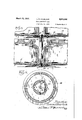
- Fig. 1 is a side elevation of a food container unit comprising a plurality of sub-units involving the principles of the invention.
- Fig. 2 is a plan view of the structure shown in Fig. 1 of the drawings, the lower portion thereof being a horizontal section on the line 2-2 in Fig. l of the drawings.
- Fig. 3 is an enlarged vertical section, on a 40 larger scale, on line 3-3 in Fig. 2 of the drawings.
- Fig. 4 is a horizontal section on line 4-4 in Fig. 3 of the drawings.
- the invention comprises a 45 lower base I, preferably made of sheet metal, and provided with a concentric ball race 2 at the middle portion thereof, the outer edges of said base being circular and bent down to rest upon a table or other support.
- the center post 59 3 is connected by a screw bolt 4 with the center of said base I, so that this post and base are rigidly connected.
- the sheet metal support 5' is preferably of sheet metal, and has its middle portion provided with a ball race 6 opposite the ball race 2, with the anti-friction balls I interposed between thetwo ball races thus formed.
- the base 5. turns about the screw 4 as a pivot or axis, and this base is provided with peripheral notches 8, and with re-entrant portions 9, and with pairs of.
- the 5 members of each pair being disposed at opposite sides of one of the wedge-shaped containers H, adapted to be disposed on said support.
- the inner ends of a flange III of one pair, and a flange IU of another pair are adjacent and are 10 spaced apart across the space provided by the re-entrant portion 9,, the latter and the notches 8 being each four in number, as shown, but it be ing understood that the numberwill vary in accordance with the number of containers which it is desired to support on the rotary turntable or, support 5', previously mentioned.
- any jar or container l I can be lifted above the flanges III, by placinga finger on the bottom of the jar or container, where the lat- 2O ter is exposed by one of the notches 8, and thus any container can be removed without disturbing any of the other containers.
- Radial beads l2 on the upper surface of the support 5 may be employed to define the divisions between the wedgeshaped containers II, as shown in dotted lines in Fig. 2 of the drawings, thereby defining the positions of the containers on the top of the rotary support.
- each pair of flanges I0 is capable of resisting not only outward or tangential displacement of its allotted container, but also any lateral displacement thereof.
- the support 5 rotates freely on the balls I, and the latter are held in position in the ball races by the plate 13, or by any other suitable means.
- a base l4 similar to that previously described, and a rotary support I 5, also similar to that previously described, are held in place by a screw bolt i6, similar to the 40 bolt 4 previously described, but the bottom bolt is upside down, while the bolt I6 is right side up.
- the base is held stationary on the post 3, in any suitable way, and balls H are interposed between ball races on the base l4 and the support [5, whereby the latter is free to rotate about the vertical axis thus provided.
- the base l4 has peripheral notches, similar to the notches 8 already described, and also has flanges l8 similar to the flanges I0 previously described, which flanges embrace the wedge-shaped containers IS, the latter-being similar to containers H, previously described.
- a plate 20 serves to keep the balls 1
- the containers preferably have covers 2
- washers 22 and 23 are applied to the lower and upper ends of the post 3, on the screws 4 and IE, to insure against loosening of the screw bolts 4 and I6, and so that the bases l and M will be held rigid with the post 3, when the latter is coupled in place between the threaded end portions of said screw, but permitting either rotary support ll or ,l5 to rotate in either direction independently of each other.
- the element 23 is flat sided, and the same is true of the element 22, so that a wrench can be applied thereto to tighten or loosen'them.
- the upper base I5 may have radial ribs like the ribs I2 previously described, to define the radial divisions between the containers IS, the latter bein shaped like the containers H, previously described.
- any container of the lower sub-unit comprising the jars or containers I I, may be removed independently of the others, and any. container of the upper sub-unit may be similarly removed.
- the lower sub-unit can be rotated, in either direction, independently of the upper sub-unit, and the latter may be rotated in either direction, independently of the lower sub-unit, whereby either sub-unit may be placed in position to facilitate the removal of a jar or container from the front side thereof, which means the side facing the person using or operating thestructure.
- the upper base 14 does not need to be of the same diameter as the lower base I, but in the manufacture of this structure, there are advantages in having the two or more bases of the same size, as that means that only one size of base needs to be made, instead of increasing the manufacturing expense by having bases of diiferent sizes, requiring dies or other tools of different shapes or sizes It will also be seen that the rotary supports may all be alike, and that the post 3 is the same at each end, and that the screw bolts are threaded alike, to engage either end of the post 3, whereby the cost of production is practically reduced to a minimum.
- the same parts can be used for the manufacture of single sets, a food unit comprising a single horizontal set of containers, or of multiple sets-of the kind shown and described, each multiple set constituting a food unit in its entirety.
- the unitary structure shown and described may be called a double deck food unit, but it is obvious that the invention contemplates a plurality of sub-units or individually'rotatable sets of containers, and is not limited to any particular number of horizontal levels, in which the sets of jars or containers are arranged.
- central vertical or axial post of the structure is provided with similar upper and lower ends, so that these ends are interchangeable with each other in the struc-- ture, which obviously tends to facilitate the assembling of the different parts.
- the base I and its allotted rotary support can be assembled, by inserting the screw or bolt 4 through the element 22, so that the base and its rotary support are properly held between the head of the screw 4 and the said element 22, with the threaded end of the screw extending upwardly.
- the base l4 and the rotary support l5 can be assembled in the same way, by using the element 33, thus leaving the threaded end portion of the screw extending downwardly.
- the post 3 can be screwed onto the threaded portion of the screw 4, and the threaded portion of the screw Hi can then be screwed into the upper end of the post, and in this way the two bases are rigidly connected together, leaving their allotted rotary supports to rotate freely on the anti-friction ball bearings.
- the base I4 is preferably a duplicate of the base I
- the rotary support I5 is preferably a duplicate of the rotary support 5
- the manufacture of food units of this kind is simplified, and that the cost of manufacture is reduced, inasmuch as only one form of base is necessary, and only one form of rotary support.
- either sub-unit, with its allotted base and rotary support can be used separately and alone, as either base is adapted to. rest on a shelf or table or other support.
- a double rotary food container unit the combination of a lower stationary base adapted to rest upon a table or other object, a rotary support on said base, adapted to receive a lower group of containers, a lower screw inserted upwardly through said base and support, forming the axis of rotation of the latter, an upper stationary base spaced a distance above said support, a rotary support on said upper base, adapted to receive an upper group of containers, an upper screw inserted downwardly through said upper support and its base, and a post screwed onto the threaded portions of said screws to rigidly and detachably couple the upper base to the lower base, while permitting each support to rotate independently of the other.
- a rotary food container unit the combination of a base adapted to rest on a shelf or table, a rotary support on said base, adapted to hold a group of containers in a circle, a vertical post axially and rigidly but detachably connected at its lower end with said-base, a duplicate base rigidly and axially but detachably mounted on the upper end of said post, and a duplicate rotary support on said upper base, so that only one form of base and one form of rotary support are necessary in the manufacture of the unit, and whereby the containers on said upper base are interchangeable with the containers on the lower base, with each base and its allotted rotary support forming a sub-unit adapted for use alone.
Description
March 23, 1937. scuRLocK FOOD CONTAINER UNIT Filed July 11, 19 35 2 Sheets-Sheet l I March 23, 1937. I H. scuRLoCK FOOD CONTAINER UNIT Filed July 11, 1935 2 Sheets-Sheet? Patented Mar. 23, 1937 ,"UNITED STATES PATENT OFFICE This invention relates to food container units of that kind in which a plurality of containers, preferably made of glass, are arranged in a circle=on a rotary support, with a base for the. latter, and with provisions on the support to prevent the containers from being accidentally displaced therefrom, notwithstanding that. each container is preferably. removable from the support without the necessity of removing any of the other containers of the group. i
, Generally stated, the object of the invention istoprovide a novel and improved construction andiarrangement whereby a rotary supporting structure is. provided, of metal or other suitable 15 materials, of such shape and character that the containers may be arrangedin. two or more groups, one above the other, with each group disposed .in a horizontal plane, and with themembers of each group disposed in a circle on its 2D own individual rotary support, whereby any group may be rotated in either direction.
it is also an. object to provide certain details and features of construction and combinations ten-ding to increase the general efficiency and 25 the desirability of a food container unit having. a plurality of sub-units, of this particular character.
To the foregoing and other useful ends, the invention consists in matters hereinafter set forth 30 and claimed and shown in the accompanying drawings, in which- Fig. 1 is a side elevation of a food container unit comprising a plurality of sub-units involving the principles of the invention.
35 Fig. 2 is a plan view of the structure shown in Fig. 1 of the drawings, the lower portion thereof being a horizontal section on the line 2-2 in Fig. l of the drawings. Fig. 3 is an enlarged vertical section, on a 40 larger scale, on line 3-3 in Fig. 2 of the drawings.
Fig. 4 is a horizontal section on line 4-4 in Fig. 3 of the drawings.
. As thus illustrated, the invention comprises a 45 lower base I, preferably made of sheet metal, and provided with a concentric ball race 2 at the middle portion thereof, the outer edges of said base being circular and bent down to rest upon a table or other support. The center post 59 3 is connected by a screw bolt 4 with the center of said base I, so that this post and base are rigidly connected. The sheet metal support 5' is preferably of sheet metal, and has its middle portion provided with a ball race 6 opposite the ball race 2, with the anti-friction balls I interposed between thetwo ball races thus formed. The base 5. turns about the screw 4 as a pivot or axis, and this base is provided with peripheral notches 8, and with re-entrant portions 9, and with pairs of. outwardly converging flanges In, the 5 members of each pair being disposed at opposite sides of one of the wedge-shaped containers H, adapted to be disposed on said support. Thus, the inner ends of a flange III of one pair, and a flange IU of another pair, are adjacent and are 10 spaced apart across the space provided by the re-entrant portion 9,, the latter and the notches 8 being each four in number, as shown, but it be ing understood that the numberwill vary in accordance with the number of containers which it is desired to support on the rotary turntable or, support 5', previously mentioned. With this construction, any jar or container l I can be lifted above the flanges III, by placinga finger on the bottom of the jar or container, where the lat- 2O ter is exposed by one of the notches 8, and thus any container can be removed without disturbing any of the other containers. Radial beads l2 on the upper surface of the support 5 may be employed to define the divisions between the wedgeshaped containers II, as shown in dotted lines in Fig. 2 of the drawings, thereby defining the positions of the containers on the top of the rotary support. But it will be seen that each pair of flanges I0 is capable of resisting not only outward or tangential displacement of its allotted container, but also any lateral displacement thereof. The support 5 rotates freely on the balls I, and the latter are held in position in the ball races by the plate 13, or by any other suitable means.
Upon the top of the post 3', a base l4, similar to that previously described, and a rotary support I 5, also similar to that previously described, are held in place by a screw bolt i6, similar to the 40 bolt 4 previously described, but the bottom bolt is upside down, while the bolt I6 is right side up. The base "is held stationary on the post 3, in any suitable way, and balls H are interposed between ball races on the base l4 and the support [5, whereby the latter is free to rotate about the vertical axis thus provided. The base l4 has peripheral notches, similar to the notches 8 already described, and also has flanges l8 similar to the flanges I0 previously described, which flanges embrace the wedge-shaped containers IS, the latter-being similar to containers H, previously described. A plate 20 serves to keep the balls 1|! in their races, in the well known manner.
The containers preferably have covers 2|, as shown more clearly in Fig. 3 of the drawings.
Preferably, washers 22 and 23 are applied to the lower and upper ends of the post 3, on the screws 4 and IE, to insure against loosening of the screw bolts 4 and I6, and so that the bases l and M will be held rigid with the post 3, when the latter is coupled in place between the threaded end portions of said screw, but permitting either rotary support ll or ,l5 to rotate in either direction independently of each other. As shown in Fig. 4, the element 23 is flat sided, and the same is true of the element 22, so that a wrench can be applied thereto to tighten or loosen'them. It
will be understood that the upper base I5 may have radial ribs like the ribs I2 previously described, to define the radial divisions between the containers IS, the latter bein shaped like the containers H, previously described.
Thus, with the construction shown and described, any container of the lower sub-unit, comprising the jars or containers I I, may be removed independently of the others, and any. container of the upper sub-unit may be similarly removed. The lower sub-unit can be rotated, in either direction, independently of the upper sub-unit, and the latter may be rotated in either direction, independently of the lower sub-unit, whereby either sub-unit may be placed in position to facilitate the removal of a jar or container from the front side thereof, which means the side facing the person using or operating thestructure.
The upper base 14, of course, does not need to be of the same diameter as the lower base I, but in the manufacture of this structure, there are advantages in having the two or more bases of the same size, as that means that only one size of base needs to be made, instead of increasing the manufacturing expense by having bases of diiferent sizes, requiring dies or other tools of different shapes or sizes It will also be seen that the rotary supports may all be alike, and that the post 3 is the same at each end, and that the screw bolts are threaded alike, to engage either end of the post 3, whereby the cost of production is practically reduced to a minimum. Again, should it be desired to use the parts shown and described for theproduction of units having only a single level of containers, with only one rotary support, it is obvious that the parts shown and described are sufficient for that purpose, inasmuch as the post 3 can be left off, and the upper portion of the screw 4 can be cut off and riveted over the top of the washer 22; or for a single set of containers, the screw can be turned right side up, as shown in the upper portion of Fig. 3 of the drawings, and'the lower end portion can be cut off and riveted over the bottom of the washer 23, if so desired. Thus the same parts can be used for the manufacture of single sets, a food unit comprising a single horizontal set of containers, or of multiple sets-of the kind shown and described, each multiple set constituting a food unit in its entirety. The unitary structure shown and describedmay be called a double deck food unit, but it is obvious that the invention contemplates a plurality of sub-units or individually'rotatable sets of containers, and is not limited to any particular number of horizontal levels, in which the sets of jars or containers are arranged. The point is that-the jars or containers, and the plurality of levels, each set rotatable independently of the others, about a common vertical axis, are each removable independently without disturbing any of the other jars or containers, which means without disturbing the positions of any of the other containers on their respective rotary supports.
Of course, it will be observed that certain features of the invention are susceptible of use in a structure in which the two or more sub-units or container sets are not rotatable independently of each other, but are mounted to rotate in unison, so that when one set is turned'in one direction, the other set or sets will rotate in the same direction. But, as shown and described, the two or more sets are each independently r tatable, so that any set may be rotated without rotating or disturbing any other set.
It will also be seen that the central vertical or axial post of the structure is provided with similar upper and lower ends, so that these ends are interchangeable with each other in the struc-- ture, which obviously tends to facilitate the assembling of the different parts.
While the structure shown and described is preferably provided with wedge-shaped jars or containers, as a matter of efiiciency in utilizing space, it is obvious that the invention may be used in connection with jars or containers of any suitable or desired shape, and that the rotary supports therefor may be suitably shaped or formed to adequately support and hold the desired jars or containers.
In assembling the unit shown and described, it is obvious that the base I and its allotted rotary support can be assembled, by inserting the screw or bolt 4 through the element 22, so that the base and its rotary support are properly held between the head of the screw 4 and the said element 22, with the threaded end of the screw extending upwardly. The base l4 and the rotary support l5 can be assembled in the same way, by using the element 33, thus leaving the threaded end portion of the screw extending downwardly. Then the post 3 can be screwed onto the threaded portion of the screw 4, and the threaded portion of the screw Hi can then be screwed into the upper end of the post, and in this way the two bases are rigidly connected together, leaving their allotted rotary supports to rotate freely on the anti-friction ball bearings.
As the base I4 is preferably a duplicate of the base I, and inasmuch as the rotary support I5 is preferably a duplicate of the rotary support 5, it follows that the manufacture of food units of this kind is simplified, and that the cost of manufacture is reduced, inasmuch as only one form of base is necessary, and only one form of rotary support. In addition, as shown, either sub-unit, with its allotted base and rotary support, can be used separately and alone, as either base is adapted to. rest on a shelf or table or other support. As the two ends of the post 3 are the same, and are interchangeable, it follows that a further simplification is obtained, as the same means can be employed for drilling and threading both ends of the rod, and in assembling the parts the workers do not have to be particular which end of the post is uppermost.
What I claim as my invention is:
1. In a double rotary food container unit, the combination of a lower stationary base adapted to rest upon a table or other object, a rotary support on said base, adapted to receive a lower group of containers, a lower screw inserted upwardly through said base and support, forming the axis of rotation of the latter, an upper stationary base spaced a distance above said support, a rotary support on said upper base, adapted to receive an upper group of containers, an upper screw inserted downwardly through said upper support and its base, and a post screwed onto the threaded portions of said screws to rigidly and detachably couple the upper base to the lower base, while permitting each support to rotate independently of the other.
2. A structure as specified in claim 1, comprising retaining means on the lower screw, be-
tween the top of the lower support and the lower end of said post, and retaining means on the upper screw, between the bottom of the upper support and the upper end of said post.
3. A structure as specified in claim 1, the upper base having a fiat bottom and thereby when detached from said post being adapted with its allotted rotary support to rest on a table or other object, so that each group can be used separately as a single unit if desired.
4. In a rotary food container unit, the combination of a base adapted to rest on a shelf or table, a rotary support on said base, adapted to hold a group of containers in a circle, a vertical post axially and rigidly but detachably connected at its lower end with said-base, a duplicate base rigidly and axially but detachably mounted on the upper end of said post, and a duplicate rotary support on said upper base, so that only one form of base and one form of rotary support are necessary in the manufacture of the unit, and whereby the containers on said upper base are interchangeable with the containers on the lower base, with each base and its allotted rotary support forming a sub-unit adapted for use alone.
LEWIS H. SCURLOCK.
Priority Applications (1)
| Application Number | Priority Date | Filing Date | Title |
|---|---|---|---|
| US30863A US2074564A (en) | 1935-07-11 | 1935-07-11 | Food container unit |
Applications Claiming Priority (1)
| Application Number | Priority Date | Filing Date | Title |
|---|---|---|---|
| US30863A US2074564A (en) | 1935-07-11 | 1935-07-11 | Food container unit |
Publications (1)
| Publication Number | Publication Date |
|---|---|
| US2074564A true US2074564A (en) | 1937-03-23 |
Family
ID=21856404
Family Applications (1)
| Application Number | Title | Priority Date | Filing Date |
|---|---|---|---|
| US30863A Expired - Lifetime US2074564A (en) | 1935-07-11 | 1935-07-11 | Food container unit |
Country Status (1)
| Country | Link |
|---|---|
| US (1) | US2074564A (en) |
Cited By (9)
| Publication number | Priority date | Publication date | Assignee | Title |
|---|---|---|---|---|
| US2779158A (en) * | 1951-06-26 | 1957-01-29 | Dungan Richard Thomas | Control for non-hypergolic liquid propellant rocket engines |
| US2935288A (en) * | 1956-04-19 | 1960-05-03 | Admiral Corp | Cabinet support |
| US2998814A (en) * | 1958-09-03 | 1961-09-05 | James C Forsberg | Barbecue fuel tray mechanism |
| US3397805A (en) * | 1967-03-13 | 1968-08-20 | Rubbermaid Inc | Rotary tiered canister set |
| US4140223A (en) * | 1977-08-24 | 1979-02-20 | Rau Arthur G | Tiered rotatable spice-cans storage unit |
| US4929457A (en) * | 1987-12-30 | 1990-05-29 | Takayoshi Sato | Ice-cream cones |
| US5335804A (en) * | 1991-12-20 | 1994-08-09 | Flory Vera A | Canister |
| US5641080A (en) * | 1995-05-24 | 1997-06-24 | Gerber Products Company | Carousel storage assembly |
| US8887930B1 (en) * | 2011-08-24 | 2014-11-18 | Mark A. Krull | Organizational storage system |
-
1935
- 1935-07-11 US US30863A patent/US2074564A/en not_active Expired - Lifetime
Cited By (11)
| Publication number | Priority date | Publication date | Assignee | Title |
|---|---|---|---|---|
| US2779158A (en) * | 1951-06-26 | 1957-01-29 | Dungan Richard Thomas | Control for non-hypergolic liquid propellant rocket engines |
| US2935288A (en) * | 1956-04-19 | 1960-05-03 | Admiral Corp | Cabinet support |
| US2998814A (en) * | 1958-09-03 | 1961-09-05 | James C Forsberg | Barbecue fuel tray mechanism |
| US3397805A (en) * | 1967-03-13 | 1968-08-20 | Rubbermaid Inc | Rotary tiered canister set |
| US4140223A (en) * | 1977-08-24 | 1979-02-20 | Rau Arthur G | Tiered rotatable spice-cans storage unit |
| US4929457A (en) * | 1987-12-30 | 1990-05-29 | Takayoshi Sato | Ice-cream cones |
| US5335804A (en) * | 1991-12-20 | 1994-08-09 | Flory Vera A | Canister |
| US5641080A (en) * | 1995-05-24 | 1997-06-24 | Gerber Products Company | Carousel storage assembly |
| US8887930B1 (en) * | 2011-08-24 | 2014-11-18 | Mark A. Krull | Organizational storage system |
| US20150157157A1 (en) * | 2011-08-24 | 2015-06-11 | Swagel Darrin M | Organizational Storage System |
| US9107527B2 (en) * | 2011-08-24 | 2015-08-18 | Mark A. Krull | Organizational storage system |
Similar Documents
| Publication | Publication Date | Title |
|---|---|---|
| US2074564A (en) | Food container unit | |
| US3858529A (en) | Knock-down multiple shelf assembly, particularly a lazy susan | |
| US1977092A (en) | Food container unit | |
| US4892197A (en) | Golf ball display stand | |
| US2600922A (en) | Outer bearing for rotatable servers | |
| CN206594899U (en) | College Maths probability event teaching demonstration device | |
| US1978695A (en) | Revolving tray | |
| US2488641A (en) | Revolving display rack for showcases | |
| US3715815A (en) | Learning center | |
| US2091394A (en) | Food container | |
| US6591993B2 (en) | Rotating lamp shade display carousel system | |
| US1755477A (en) | Display revolving stand | |
| US1927283A (en) | Display stand | |
| US1533500A (en) | Device for demonstrating angular momentum | |
| US1781015A (en) | Revolving table | |
| US1053742A (en) | Table. | |
| US932931A (en) | Apparatus for recovering liquids from receptacles. | |
| US2330702A (en) | Spool rack | |
| US2236492A (en) | Ball bearing screw and nut portion | |
| US2193384A (en) | Serving stand | |
| US2198091A (en) | Rotatable server | |
| US1718881A (en) | Laundry rack | |
| WO2009051568A1 (en) | Assembly of rotatable shelves in a furniture element | |
| CN100518587C (en) | Swivel block style rotating wine rack | |
| US2259876A (en) | Frog feeding device |