US2069578A - Electric brake - Google Patents
Electric brake Download PDFInfo
- Publication number
- US2069578A US2069578A US606484A US60648432A US2069578A US 2069578 A US2069578 A US 2069578A US 606484 A US606484 A US 606484A US 60648432 A US60648432 A US 60648432A US 2069578 A US2069578 A US 2069578A
- Authority
- US
- United States
- Prior art keywords
- cylinder
- piston
- pedal
- valve
- rod
- Prior art date
- Legal status (The legal status is an assumption and is not a legal conclusion. Google has not performed a legal analysis and makes no representation as to the accuracy of the status listed.)
- Expired - Lifetime
Links
Images

Classifications
-
- B—PERFORMING OPERATIONS; TRANSPORTING
- B60—VEHICLES IN GENERAL
- B60T—VEHICLE BRAKE CONTROL SYSTEMS OR PARTS THEREOF; BRAKE CONTROL SYSTEMS OR PARTS THEREOF, IN GENERAL; ARRANGEMENT OF BRAKING ELEMENTS ON VEHICLES IN GENERAL; PORTABLE DEVICES FOR PREVENTING UNWANTED MOVEMENT OF VEHICLES; VEHICLE MODIFICATIONS TO FACILITATE COOLING OF BRAKES
- B60T13/00—Transmitting braking action from initiating means to ultimate brake actuator with power assistance or drive; Brake systems incorporating such transmitting means, e.g. air-pressure brake systems
- B60T13/74—Transmitting braking action from initiating means to ultimate brake actuator with power assistance or drive; Brake systems incorporating such transmitting means, e.g. air-pressure brake systems with electrical assistance or drive
- B60T13/745—Transmitting braking action from initiating means to ultimate brake actuator with power assistance or drive; Brake systems incorporating such transmitting means, e.g. air-pressure brake systems with electrical assistance or drive acting on a hydraulic system, e.g. a master cylinder
Definitions
- the present invention relates to brakes and more particularly to a fluid pressure and electrical system for the operation of the brakes of -a vehicle. 1
- An object of the present invention is to provide a braking system for vehicles in which the brakes will be operated by hydraulic means, the pressure for said hydraulic means being supplied byelectrical means under the control of the operator.
- Another object of the invention is to provide a braking system including electrical means, operable at the will of the operator for applying pressure to an hydraulic system, the pressure in which effects application of the brakes.
- Another object of the present invention is to provide an hydraulic and electrical braking system in which the brakes are maintained at any desired degree of application by means operated automatically but always under the control of 20 the operator.
- a further object is to provide an hydraulic and electrical braking system including a novel valve device which is self-lapping at the will of the operator for maintaining the brakes at any 25 desired degree of application. 7
- a still further object is to provide an hydraulic and electrical braking system in which a discontinuation of the application of positive pressure to thebrake pedal will cause self-lapping operation of parts of the system, whereby the brakes will be automatically maintained in ap-- 1plied condition by hydraulic pressure in the sysem.
- Fig. 1 is a view showing the disposition of the Fig. 4 is a view, partly in section, of an hy-' as draulic and electrical braking. system in which the brakes are adapted to be applied by hydraulic means. a 7
- a foot pedal I has been provided, such pedalhaving no fixed pivot.
- Pivotally connected to pedal 'I at point 2 is one end of a push-rod 3, the same being attached at its other end to a piston 4 which is slidable a cylinder 5 and normally maintained at one end of said cylinder by a spring Ii, disposed between one end of said cylinder and said piston.
- the spring 6 normally urges the piston 4, push-rod 3 and'pedal I to such a position as to maintain these'parts in their inoperative or retracted position.
- An additional retracting spring I may be provided, the same being shown as being disposed between the pedal I and the cylinder 5.
- a cylindrical extension 8 Formed-on the end of the cylinder 5 at which the piston 4 remains in its inoperative or retracted position, and extending externally thereof is a cylindrical extension 8,- the interior of the same being open at one end to the cylinder 5 in front of piston 4 and at its other. end to a pipe or tube 9 which is in constant, open communication with a cylinder III.
- ' spring-pressed ball-check valve II is disposed within the cylindrical extension -8 and prevents any flow of fluid from cylinder 5 to cylinder l0, although allowing flow in the opposite direction.
- Means are provided for forcing fluid, which 0 may comprise any suitable liquid from cylinder III through tube 9 into cylinder 5 to thereby move piston 4 to the left as viewed in Fig. 2, such means comprising a piston I2, disposed in cylinder Ill and attached by means of a rod I3 to the armature I4 of a solenoid, the windings of which are designated by the numeral I5.
- a spring I6 is provided within cylinder IIland bears against one end of said cylinder and against piston I2, thereby maintaining said piston and the armature 40 I4 in inoperative or retracted position.
- Means are provided for controlling, at the will of the operator, the energization orv deenergization of the solenoid windings I5.
- Such means include a switch member I6 carried by a rod' I'I whichis pivotally connected at one end to the pedal I, at the point I8 and at its other end is journaled in a tubular extension 25 formed on one end of a cylinder 24 for sliding movement therethrougln
- the switch member I6 is thereforemovable with pedal land is connected in the circuit I9 .of the solenoid windings.
- a fixed switch member is also provided, such member. comprising afixed tubular member 20 being closed at one end andopen at its other end, said open 5 end.
- Cylinder 24 is closed at one end by the cover or extension 25 in which the rod I1 has a slidable fit, said rod extending through the cover and, when the pedal I is in completely retracted position, having one end flush with the inner wall of cover 25. Cylinder 24 is in communication with cylinder 5 through a pas sage 26 which connects adjacent ends of such cylinders.
- Piston 21 Disposed within cylinder 24 is a piston 21 which is normally maintained against the end of the cylinder through which rod I1 extends, it being held in this position by means which will appear hereinafter.
- Piston 21 is formed, on its inner face, with a tubular extension 28, one end of which is formed with an opening througl: vhicha headed valve rod passes, the
- valve member 29 Formed on the other end of the valve rod is a valve member 29 which is normally maintained away from, but may seat on, a valve seat 33 formed in the end of the cylinder and communicating with a pipe 3
- communicates at one end with cylinder 24 through valve seat 33 and at its other end is in constant communication with a reservoir 32.
- Reservoir 32 also communicates with cylinder I3 past a springpressed ball-check valve 33 which allows passage of fluid from reservoir 32 to cylinder III but not in the opposite direction.
- a vent 32" may be formed in reservoir 32, although such is not requisite to the proper operation of the system.
- Means are provided for eflecting the operation of the brakes by the structure described hereinbefore, such means comprising a lever 33, mounted on a fixed pivot 34 and pivotally connected at its upper end to rod 3 at point 33. At its lower end lever 33 is plvotally connected to a brakerod 36.
- lever 33 may-be connected at its upper end to pedal I as shown in Fig.3. It'will be obvious that this construction will result in greater pedal pressure, the foot supplying a larger proportion of the braking power than in the construction in Fig. 2.
- valve 29 is maintained seated.
- the liquid pressure acting to the left on piston 21' will not of course unseat valve 23, as piston 21 will be maintained in its position by foot-pressure exerted through rod I1.
- lever I will, in effect, be a beam acted on to the left by the foot, piston4 and piston 21, the sum of the three-forces being transmitted to the brake lever 33 at point 33, to thereby rock lever 33 about point 34 and apply the brakes.-
- the lever I pivots about the foot of the operator in a clockwise direction, due to the forces I exerted by the pistons 4 and 21. It will be understood that the return spring 1 tends to hold the pedal pad of the lever I against the foot of the operator under conditions of brake actuation.
- Fluid underpressure will therefore be sealed in cylinders 5 and 24 bycheck valve II and valve 23. It will be apparent that the brakes have thus been applied to a desired degree, and maintained at this degree of applicationby what might be termed an hydraulic ratchet. If it is now desired to release the brakes, foot-pressure on pedal I is releasedand since such foot-pressure was balanced by the force exerted on the pedal by piston'21 through rod I1, lever I will rock about point 2 in a clockwise direction, and rod I1 and piston 21 will move to the left in Fig. 2 until the tubular extension 23 moves valve 23 from seat 33 by engaging the head on the valve rod. Liquid will now be released from cylinder 3, through passage 23, cylinder 24, pipe 3I reservoir 32, past check valve 33 to cylinder I II. Springs 3 and It will aid spring 1 in returning the parts to their inoperative positions and the brakes to released position.
- Rod 54 attached to the lower end of pedal 50, is moved to the right by such pedal movement, thereby causing lever 51 to rock about its fixed pivot 58, and move rod 59 attached to the lower end of lever 51, to the left in Fig. 4.
- Such movement of rod 59 exerts a force on piston 60 in cylinder 6
- Subsequent movement of pedal 50 causes switch member '55, carried by rod 5 3, to contact fixed switch member 56, thereby energizing solenoid coils 53 and moving solenoid armature 52 to the left in Fig. 4.
- Piston 63 in cylinder 64 is rigidly connected to armature 52 by connecting rod 65 and is moved to the left with said armature against the force of spring 66, thereby forcing liquid under pressure past ballcheck valve 61 and through pipes 68 and 69.
- Fluid forced through pipe 68 is transmitted through suitable passages to hydraulic brake-operating cylinders 10 for operating the vehicle
- Fluid forced through pipe 69 is con- 1 brakes. ducted to cylinder 61 and exerts a pressure on piston 60 in a direction opposite to the pressure thereon caused by foot-pressure on pedal 50. Any cessation of such foot-pressure will result in a continued movement of piston 63 until sufficient pressure has been built up in cylinder iii to move piston 60 to the right, thereby causing a leftward movement of rod 54 to open the switch contacts 55, '56 thereby de-energizing coils 53.
- a brake pedal In a system for operating vehicle brakes, a brake pedal, braking connections associated therewith, fluid-operated means for moving said connections by power, motive means for supply,-
- a manually-operated part for closing an electric circuit
- a fluid-operated piston for applying the brakes by power
- a second piston moved on energization of said circuit for applying pressure to said first piston
- means operable by said first piston for applying said brakes and exerting a force on said manually-operated part
- a thirdpiston operated by'pressure exerted by said second piston for controlling said electric circuit.
- manually-operable means an hydraulically-operated device, com-' movable in one direction with said manuallyoperable means, and in the opposite direction by a pressure differential applied to said motor to move the latter in said one direction.
- a manually-operated member an hydraulic actuator therefor, an electrical device for 'operatingsaid hydraulic actuator, switch means operated by said manually-operated member for controlling said electrical device, and means including a valve device, manually-operable for closing said switch means to operate said device and actuator to apply the brakes, and to interrupt said switch means and hold the brakes applied.
- an hydraulic actuator In a braking system, an hydraulic actuator, a switch-controlled electrical device for operating said hydraulic actuator, and means for controlling the operation of said hydraulic-actuator, said means comprising a cylinder, 2. piston slidable therein, a manually-controlled rod abutting said piston, a valvemeans carried by said piston and having a lost-motion connection therewith, and connections between said cylinder and said hydraulic actuator.
- a manually-operated member braking cgennections associated therewith, an hydraulic actuator connected with said member, electrical means for causing operation of said actuator, a piston device movable in one direction by said manually-operated member,
- valve means carried by said piston device, and means for moving said piston device in an opposite direction when the brakes are applied to a selected extent for rendering said electrical means inoperative and for maintaining said brakes applied to said extent.
- draulic system a device adapted to be operated by fluid in said system, electrical means for causing operation of said device, a valve in said sys-v tem for controlling the operation of said device, switch means for said electrical means, said valve means and said switch being simultaneously manually movable in one direction and separately movable in the other direction, said last named movement effecting movement of said switch prior to movement of said valve means.
- A- fluid-pressure braking system comprising a brake pedal, brake-operating connections associated with said pedal, a fluid-pressure actuator connected with said pedal for applying the brakes ,by power, means for controlling said actuator 1,
- trolling circuit manually operable means for etiecting energization of said circuit, braking connections directly connected with said means, a fluid motor connected with said connections, means operable upon eners'ization 0! said circult to conduct fluid pressure to said motor. and means separate from said last named means and 4 spears-7e operable by fluid pressure supplied said motor for interrupting said power controlling circuit and for holding the brakes applied when the braking connections have been actuated a desired amount.
Description
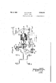
Feb. 2, 1937. w. A. EATON ELECTRIC BRAKE Filed April 20, 1932 2 SheetS -rShGet 1 m m m m AT RNEY W. A. EATON ELECTRIC BRAKE Feb. 2, 1937.
Filed Ap ril 20, 1952 2 Sheets-Sheet 2 INVENTOR "ATTORNEY:
Patented Feb. 2, 1937 UNITED STATES 2,069,578 ELECTRIC BRAKE Wilfred A. Eaton, Pittsburgh, la., assignor to Bendix Westinghouse Automotive Air Brake Company, Pittsburgh, Pa., a corporation of Delaware Application April 20, 1932, Serial No. 606,484
' 10 Claims. (Cl. 188--15 2) The present invention relates to brakes and more particularly to a fluid pressure and electrical system for the operation of the brakes of -a vehicle. 1
5 An object of the present invention is to provide a braking system for vehicles in which the brakes will be operated by hydraulic means, the pressure for said hydraulic means being supplied byelectrical means under the control of the operator.
10 Another object of the invention is to provide a braking system including electrical means, operable at the will of the operator for applying pressure to an hydraulic system, the pressure in which effects application of the brakes.
15 Another object of the present invention is to provide an hydraulic and electrical braking system in which the brakes are maintained at any desired degree of application by means operated automatically but always under the control of 20 the operator.
A further object is to provide an hydraulic and electrical braking system including a novel valve device which is self-lapping at the will of the operator for maintaining the brakes at any 25 desired degree of application. 7
A still further object is to provide an hydraulic and electrical braking system in which a discontinuation of the application of positive pressure to thebrake pedal will cause self-lapping operation of parts of the system, whereby the brakes will be automatically maintained in ap-- 1plied condition by hydraulic pressure in the sysem.
Other objects and features of novelty will appear more clearly from the following detailed description taken in connection with the accompanying drawings, which illustrate one embodiment of the invention. It is to be expressly understood, however, that the drawings are for pur- 40 poses of illustration only and are not designed as a definition of the limits of the invention, reference being had for this purpose to the appended claims.
Referring to the drawings: Fig. 1 is a view showing the disposition of the Fig. 4 is a view, partly in section, of an hy-' as draulic and electrical braking. system in which the brakes are adapted to be applied by hydraulic means. a 7
Referring to the drawings, and more particularly to Fig. 2 thereof, it will be seen that a foot pedal I has been provided, such pedalhaving no fixed pivot. Pivotally connected to pedal 'I at point 2 is one end of a push-rod 3, the same being attached at its other end to a piston 4 which is slidable a cylinder 5 and normally maintained at one end of said cylinder by a spring Ii, disposed between one end of said cylinder and said piston. The spring 6 normally urges the piston 4, push-rod 3 and'pedal I to such a position as to maintain these'parts in their inoperative or retracted position. An additional retracting spring I may be provided, the same being shown as being disposed between the pedal I and the cylinder 5. Formed-on the end of the cylinder 5 at which the piston 4 remains in its inoperative or retracted position, and extending externally thereof is a cylindrical extension 8,- the interior of the same being open at one end to the cylinder 5 in front of piston 4 and at its other. end to a pipe or tube 9 which is in constant, open communication with a cylinder III. A
' spring-pressed ball-check valve II is disposed within the cylindrical extension -8 and prevents any flow of fluid from cylinder 5 to cylinder l0, although allowing flow in the opposite direction.
Means are provided for forcing fluid, which 0 may comprise any suitable liquid from cylinder III through tube 9 into cylinder 5 to thereby move piston 4 to the left as viewed in Fig. 2, such means comprising a piston I2, disposed in cylinder Ill and attached by means of a rod I3 to the armature I4 of a solenoid, the windings of which are designated by the numeral I5. A spring I6 is provided within cylinder IIland bears against one end of said cylinder and against piston I2, thereby maintaining said piston and the armature 40 I4 in inoperative or retracted position. Means are provided for controlling, at the will of the operator, the energization orv deenergization of the solenoid windings I5. Such means include a switch member I6 carried by a rod' I'I whichis pivotally connected at one end to the pedal I, at the point I8 and at its other end is journaled in a tubular extension 25 formed on one end of a cylinder 24 for sliding movement therethrougln The switch member I6 is thereforemovable with pedal land is connected in the circuit I9 .of the solenoid windings. A fixed switch member is also provided, such member. comprising afixed tubular member 20 being closed at one end andopen at its other end, said open 5 end. being formed with an inturned marginal system to; be lapped at any desired degree of application, such means including the cylinder 24 which is shown as being formed integrally with cylinder 5, although such construction is not required as the two cylinders maybe formed entirely separately if desired. Cylinder 24 is closed at one end by the cover or extension 25 in which the rod I1 has a slidable fit, said rod extending through the cover and, when the pedal I is in completely retracted position, having one end flush with the inner wall of cover 25. Cylinder 24 is in communication with cylinder 5 through a pas sage 26 which connects adjacent ends of such cylinders. Disposed within cylinder 24 is a piston 21 which is normally maintained against the end of the cylinder through which rod I1 extends, it being held in this position by means which will appear hereinafter. Piston 21 is formed, on its inner face, with a tubular extension 28, one end of which is formed with an opening througl: vhicha headed valve rod passes, the
head of said rod being slidable within the tubular member 28,and held therein by the cover on said member. Formed on the other end of the valve rod is a valve member 29 which is normally maintained away from, but may seat on, a valve seat 33 formed in the end of the cylinder and communicating with a pipe 3| A spring 32, coiled about the valve rod and bearing at its ends against the tubular member 28 and the. valve member 29, maintains said valve rod and valve member at their fully extended position, in which valve member 29 is. adjacent but not seated on the seat 33. It will be apparent that movement of piston 21 to the right in Fig. 2 will effect the seating of valve 29 on seat 33. Pipe 3|, referred to above, communicates at one end with cylinder 24 through valve seat 33 and at its other end is in constant communication with a reservoir 32. Reservoir 32 also communicates with cylinder I3 past a springpressed ball-check valve 33 which allows passage of fluid from reservoir 32 to cylinder III but not in the opposite direction. As shown in Fig. 2 a vent 32" may be formed in reservoir 32, although such is not requisite to the proper operation of the system.
Means are provided for eflecting the operation of the brakes by the structure described hereinbefore, such means comprising a lever 33, mounted on a fixed pivot 34 and pivotally connected at its upper end to rod 3 at point 33. At its lower end lever 33 is plvotally connected to a brakerod 36.
If desired, instead of the connection shown in Fig. l, lever 33 may-be connected at its upper end to pedal I as shown in Fig.3. It'will be obvious that this construction will result in greater pedal pressure, the foot supplying a larger proportion of the braking power than in the construction in Fig. 2.
In operation, pressure to the left, as viewed in Fig. 2, on foot pedal I- causes said pedal to rock about pivot 2 so that rod I1 moves'to the right,
first forcing valve 29 against its seat 33, and upon 21 to the left in Fig. 2. It will be observed that piston 21 has already been moved to the right by rod I1, the first part of said movement causing closure of valve 29, and subsequent movement causing sliding of the valve rod head in tubular,
With the parts in the positions above described,
lever I will, in effect, be a beam acted on to the left by the foot, piston4 and piston 21, the sum of the three-forces being transmitted to the brake lever 33 at point 33, to thereby rock lever 33 about point 34 and apply the brakes.- During brake operation, the lever I pivots about the foot of the operator in a clockwise direction, due to the forces I exerted by the pistons 4 and 21. It will be understood that the return spring 1 tends to hold the pedal pad of the lever I against the foot of the operator under conditions of brake actuation. If the foot pedal is now held stationary at a point representing any given degree of brake application, current will continue to flow through magnet I1 until the hydraulic pressure in cylinders 5 and 24 has'builtup suihciently to swing pedal lever I to the left about the pedal pad as a fulcrum. When this occurs, rod I1 will also -move to the leftand move switch contact I3 away from contact 22, thereby de-energizing the solenoid coils I5. It will be observed that prior movement of rod I1 to the right in Fig. 2 results in lost motion between tubular extension 23 and the valve rod, and consequently when piston 21 moves to the left in Fig. 2 under pressure of the fluid, when further foot-pressure on pedal I is stopped, valve 29 will not be unseated. Fluid underpressure will therefore be sealed in cylinders 5 and 24 bycheck valve II and valve 23. It will be apparent that the brakes have thus been applied to a desired degree, and maintained at this degree of applicationby what might be termed an hydraulic ratchet. If it is now desired to release the brakes, foot-pressure on pedal I is releasedand since such foot-pressure was balanced by the force exerted on the pedal by piston'21 through rod I1, lever I will rock about point 2 in a clockwise direction, and rod I1 and piston 21 will move to the left in Fig. 2 until the tubular extension 23 moves valve 23 from seat 33 by engaging the head on the valve rod. Liquid will now be released from cylinder 3, through passage 23, cylinder 24, pipe 3I reservoir 32, past check valve 33 to cylinder I II. Springs 3 and It will aid spring 1 in returning the parts to their inoperative positions and the brakes to released position.
Referring to the braking system disclosed in Fig. 4 it will be seen that the same adapts-the principle of the system disclosed in Fig. 2 to a braking system in which the brakes are to be operated hydraulically. 'In this structure footpressure on the brake pedal 33 causes the same to rock in a counterclockwise direction about the point 55 at which the armature 52 of a solenoid 53 is pivotally attached to the brake pedal. As shown, the lower end of the pedal has a suitable lost motion connection with a stationary bracket 50*, such connection including a pin 50? cooperating in a slot 50 in said bracket, such construction permitting the above described pivotal movement of the brake pedal. Rod 54, attached to the lower end of pedal 50, is moved to the right by such pedal movement, thereby causing lever 51 to rock about its fixed pivot 58, and move rod 59 attached to the lower end of lever 51, to the left in Fig. 4. Such movement of rod 59 exerts a force on piston 60 in cylinder 6| effecting closure of valve 62. Subsequent movement of pedal 50 causes switch member '55, carried by rod 5 3, to contact fixed switch member 56, thereby energizing solenoid coils 53 and moving solenoid armature 52 to the left in Fig. 4. Piston 63 in cylinder 64 is rigidly connected to armature 52 by connecting rod 65 and is moved to the left with said armature against the force of spring 66, thereby forcing liquid under pressure past ballcheck valve 61 and through pipes 68 and 69.
Fluid forced through pipe 68 is transmitted through suitable passages to hydraulic brake-operating cylinders 10 for operating the vehicle Fluid forced through pipe 69 is con- 1 brakes. ducted to cylinder 61 and exerts a pressure on piston 60 in a direction opposite to the pressure thereon caused by foot-pressure on pedal 50. Any cessation of such foot-pressure will result in a continued movement of piston 63 until sufficient pressure has been built up in cylinder iii to move piston 60 to the right, thereby causing a leftward movement of rod 54 to open the switch contacts 55, '56 thereby de-energizing coils 53. If, now, foot-pressure is released from pedal'50, pressure exerted by rod 59 will be removed from piston 60; which will therefore move to the right, opening valve 52 and allowing fluid under pressure to flow from cylinder 64 and brake cylinders 10 through pipe 59, cylinder 6|, pipe II, reservoir 12, past ball-check valve 13 and into cylinder 64, thereby causing release of the brakes. It will be apparent that the structure just described includes the hydraulic ratchet or self-lapping feature which was described he'reinbefore.
While there have been illustrated and described two embodiments of the present invention, it is to be understood that the same might be embodied in various forms, and that changes in the design of the system or partsthereof may be made without departing from the spirit of the invention. Reference will therefore be had to the appended claims for a definition of the limits of the invention.
What is claimed is:
1. In a system for operating vehicle brakes, a brake pedal, braking connections associated therewith, fluid-operated means for moving said connections by power, motive means for supply,-
,. ing fluid under pressure to said first named means, electrical means controlled by said pedal for operating said motive means, and means operable when said brake pedal has been depressed to any selected position for interrupting operation of said motive means and for holding saidbrakes applied. Y
2. In a braking system, a manually-operated part for closing an electric circuit, a fluid-operated piston for applying the brakes by power, a second piston moved on energization of said circuit for applying pressure to said first piston, means operable by said first piston for applying said brakes and exerting a force on said manually-operated part, and a thirdpiston operated by'pressure exerted by said second piston for controlling said electric circuit.
3. In a braking system, manually-operable means, an hydraulically-operated device, com-' movable in one direction with said manuallyoperable means, and in the opposite direction by a pressure differential applied to said motor to move the latter in said one direction.
5. In a. braking system, a manually-operated member, an hydraulic actuator therefor, an electrical device for 'operatingsaid hydraulic actuator, switch means operated by said manually-operated member for controlling said electrical device, and means including a valve device, manually-operable for closing said switch means to operate said device and actuator to apply the brakes, and to interrupt said switch means and hold the brakes applied. v
6. In a braking system, an hydraulic actuator, a switch-controlled electrical device for operating said hydraulic actuator, and means for controlling the operation of said hydraulic-actuator, said means comprising a cylinder, 2. piston slidable therein, a manually-controlled rod abutting said piston, a valvemeans carried by said piston and having a lost-motion connection therewith, and connections between said cylinder and said hydraulic actuator.
'7. In abraking system, a manually-operated member, braking cgennections associated therewith, an hydraulic actuator connected with said member, electrical means for causing operation of said actuator, a piston device movable in one direction by said manually-operated member,
valve means carried by said piston device, and means for moving said piston device in an opposite direction when the brakes are applied to a selected extent for rendering said electrical means inoperative and for maintaining said brakes applied to said extent.
8. In a braking device, a normally open hy-,
draulic system, a device adapted to be operated by fluid in said system, electrical means for causing operation of said device, a valve in said sys-v tem for controlling the operation of said device, switch means for said electrical means, said valve means and said switch being simultaneously manually movable in one direction and separately movable in the other direction, said last named movement effecting movement of said switch prior to movement of said valve means.
9. A- fluid-pressure braking system comprising a brake pedal, brake-operating connections associated with said pedal, a fluid-pressure actuator connected with said pedal for applying the brakes ,by power, means for controlling said actuator 1,
trolling circuit, manually operable means for etiecting energization of said circuit, braking connections directly connected with said means, a fluid motor connected with said connections, means operable upon eners'ization 0! said circult to conduct fluid pressure to said motor. and means separate from said last named means and 4 spears-7e operable by fluid pressure supplied said motor for interrupting said power controlling circuit and for holding the brakes applied when the braking connections have been actuated a desired amount.
Priority Applications (1)
| Application Number | Priority Date | Filing Date | Title |
|---|---|---|---|
| US606484A US2069578A (en) | 1932-04-20 | 1932-04-20 | Electric brake |
Applications Claiming Priority (1)
| Application Number | Priority Date | Filing Date | Title |
|---|---|---|---|
| US606484A US2069578A (en) | 1932-04-20 | 1932-04-20 | Electric brake |
Publications (1)
| Publication Number | Publication Date |
|---|---|
| US2069578A true US2069578A (en) | 1937-02-02 |
Family
ID=24428166
Family Applications (1)
| Application Number | Title | Priority Date | Filing Date |
|---|---|---|---|
| US606484A Expired - Lifetime US2069578A (en) | 1932-04-20 | 1932-04-20 | Electric brake |
Country Status (1)
| Country | Link |
|---|---|
| US (1) | US2069578A (en) |
Cited By (12)
| Publication number | Priority date | Publication date | Assignee | Title |
|---|---|---|---|---|
| US2524334A (en) * | 1944-11-28 | 1950-10-03 | Sr William H Pumphrey | Control circuit for electromagnets |
| US2529076A (en) * | 1945-10-06 | 1950-11-07 | Joseph A N Dubreuil | Hand control for motor vehicles |
| US2562704A (en) * | 1945-10-08 | 1951-07-31 | Joseph A N Dubreuil | Fluid control for motor vehicles |
| US2843227A (en) * | 1955-05-09 | 1958-07-15 | Willis J Williams | Automatic hydraulic brake system |
| US2864238A (en) * | 1955-05-09 | 1958-12-16 | Lambert & Brake Corp | Fluid displacement device for hydraulic brake systems |
| US2906376A (en) * | 1957-03-06 | 1959-09-29 | Divco Wayne Corp | Non-skid braking system using pre-set pulsing action |
| US3282206A (en) * | 1964-12-21 | 1966-11-01 | Sperry Rand Corp | Hydraulically actuated print hammer for high speed printers |
| US3463276A (en) * | 1967-10-05 | 1969-08-26 | Louie J Brooks Jr | Auxiliary brake system |
| US3791469A (en) * | 1972-03-02 | 1974-02-12 | F Prosser | Apparatus for towing skiers |
| US4445330A (en) * | 1981-07-02 | 1984-05-01 | General Motors Corporation | Master cylinder assembly and booster |
| US4818036A (en) * | 1986-04-09 | 1989-04-04 | Wabco Westinghouse Fahrzeugbremsen Gmbh | Braking power transmitter |
| US20040084253A1 (en) * | 2002-10-30 | 2004-05-06 | Jan Herschel | Braking device for an industrial truck |
-
1932
- 1932-04-20 US US606484A patent/US2069578A/en not_active Expired - Lifetime
Cited By (13)
| Publication number | Priority date | Publication date | Assignee | Title |
|---|---|---|---|---|
| US2524334A (en) * | 1944-11-28 | 1950-10-03 | Sr William H Pumphrey | Control circuit for electromagnets |
| US2529076A (en) * | 1945-10-06 | 1950-11-07 | Joseph A N Dubreuil | Hand control for motor vehicles |
| US2562704A (en) * | 1945-10-08 | 1951-07-31 | Joseph A N Dubreuil | Fluid control for motor vehicles |
| US2843227A (en) * | 1955-05-09 | 1958-07-15 | Willis J Williams | Automatic hydraulic brake system |
| US2864238A (en) * | 1955-05-09 | 1958-12-16 | Lambert & Brake Corp | Fluid displacement device for hydraulic brake systems |
| US2906376A (en) * | 1957-03-06 | 1959-09-29 | Divco Wayne Corp | Non-skid braking system using pre-set pulsing action |
| US3282206A (en) * | 1964-12-21 | 1966-11-01 | Sperry Rand Corp | Hydraulically actuated print hammer for high speed printers |
| US3463276A (en) * | 1967-10-05 | 1969-08-26 | Louie J Brooks Jr | Auxiliary brake system |
| US3791469A (en) * | 1972-03-02 | 1974-02-12 | F Prosser | Apparatus for towing skiers |
| US4445330A (en) * | 1981-07-02 | 1984-05-01 | General Motors Corporation | Master cylinder assembly and booster |
| US4818036A (en) * | 1986-04-09 | 1989-04-04 | Wabco Westinghouse Fahrzeugbremsen Gmbh | Braking power transmitter |
| US20040084253A1 (en) * | 2002-10-30 | 2004-05-06 | Jan Herschel | Braking device for an industrial truck |
| US7299900B2 (en) * | 2002-10-30 | 2007-11-27 | Jungheinrich Ag | Braking device for an industrial truck |
Similar Documents
| Publication | Publication Date | Title |
|---|---|---|
| US3574413A (en) | Brake system for vehicles | |
| US2069578A (en) | Electric brake | |
| US3093120A (en) | Fluid pressure motor mechanism | |
| US2328637A (en) | Brake actuating system | |
| US2976849A (en) | Power mechanism | |
| US2685172A (en) | Power-assisted master cylinder | |
| US2704585A (en) | stromberg | |
| US2058063A (en) | Braking apparatus | |
| US2844228A (en) | Brake pedal ratio changer | |
| US2649692A (en) | Master cylinder for hydraulic braking systems | |
| US2211890A (en) | Brake mechanism | |
| US3360305A (en) | Dead man seat brake using separate hydraulic actuator | |
| US2361419A (en) | Combined air and hydraulic pressure brake actuating system | |
| USRE23081E (en) | Apparatus including power unit for | |
| US2662376A (en) | Booster unit for hydraulic pressure systems | |
| US3252382A (en) | Fluid pressure servomotor reaction control mechanism | |
| US3306043A (en) | Low travel hydraulic booster with in-line lifter | |
| US1794461A (en) | Brake-control mechanism | |
| US3625113A (en) | Hydraulic brake booster | |
| US3395946A (en) | Hydraulic brake circuit for dual vehicles | |
| US2328685A (en) | Braking system | |
| US2155226A (en) | Empty and load brake | |
| US3051530A (en) | Fluid pressure operated brake mechanism | |
| US2155030A (en) | Brake operating mechanism | |
| US2886950A (en) | Quick take-up master cylinder |