US2062008A - Uniform tension device - Google Patents
Uniform tension device Download PDFInfo
- Publication number
- US2062008A US2062008A US33994A US3399435A US2062008A US 2062008 A US2062008 A US 2062008A US 33994 A US33994 A US 33994A US 3399435 A US3399435 A US 3399435A US 2062008 A US2062008 A US 2062008A
- Authority
- US
- United States
- Prior art keywords
- fabric
- floating frame
- rollers
- festoons
- housing
- Prior art date
- Legal status (The legal status is an assumption and is not a legal conclusion. Google has not performed a legal analysis and makes no representation as to the accuracy of the status listed.)
- Expired - Lifetime
Links
Images


Classifications
-
- B—PERFORMING OPERATIONS; TRANSPORTING
- B29—WORKING OF PLASTICS; WORKING OF SUBSTANCES IN A PLASTIC STATE IN GENERAL
- B29D—PRODUCING PARTICULAR ARTICLES FROM PLASTICS OR FROM SUBSTANCES IN A PLASTIC STATE
- B29D30/00—Producing pneumatic or solid tyres or parts thereof
- B29D30/06—Pneumatic tyres or parts thereof (e.g. produced by casting, moulding, compression moulding, injection moulding, centrifugal casting)
- B29D30/38—Textile inserts, e.g. cord or canvas layers, for tyres; Treatment of inserts prior to building the tyre
-
- B—PERFORMING OPERATIONS; TRANSPORTING
- B65—CONVEYING; PACKING; STORING; HANDLING THIN OR FILAMENTARY MATERIAL
- B65H—HANDLING THIN OR FILAMENTARY MATERIAL, e.g. SHEETS, WEBS, CABLES
- B65H20/00—Advancing webs
- B65H20/30—Arrangements for accumulating surplus web
- B65H20/32—Arrangements for accumulating surplus web by making loops
- B65H20/34—Arrangements for accumulating surplus web by making loops with rollers
Definitions
- This invention relates to uniform tension devices, and more especially it relates to devices for maintaining a constant uniform tension in continuous'strip material that is unwound fro! one roll thereof, treated or processed while oil! said roll, and then rewound upon another roll.
- the invention is of major importance in the rubber industry, for example, in apparatus for processing tire building fabric.
- a method of preparing rubberized, weak-wefted cord fabric for tire casings that comprises initially impregnating the cords of the fabric with rubber composition in solution, there is provided impregnating apparatus-comprising a bath of viscous rubber composition, and a drying chamber through which the impregnated fabric passes, the feed of the fabric being constant.
- Fabric to be impregnated is withdrawn from a roll of the fabric, and since this roll becomes exhausted and requires to be replaced by a new roll, suitable fabric-storage means is provided between the supply roll and the drying chamber so that fabric may be withdrawn from the storage means during the interval required for replacing'an exhausted supply roll with a fresh one.
- a fabric-storage means is positioned at the work-delivery end of the apparatus for receiving and storing fabric from the drying chamber during the intrgal required to remove 30 .a full roll of impregnat fabric and replace it with an empty roll-she
- Both the fabric supply roll at the work-receiving end of the apparatus and the rewinding roll at the work-delivery end of the apparatus are power driven, and, because said rolls vary in diameter as fabric is removed therefrom or Wound thereon, it is necessary to provide means for constantly adjusting the speed of rotation of said rolls in; order to maintain a constant uniform tension on the fabric.
- the means by which the speed of rotation of said fabric rolls automatically is adjusted constitutes the subject matter of this invention.
- the chief objects of the invention are to produce processed tire fabric of uniform quality; to produce tire fabric of determinate stretch and crimp; to obviate mis-cuts in the subsequent cutting of continuous tire fabric into tire-building plies; and to avoid waste of tire fabric from causes arising from improper processing. More specifically the invention aims to provide means by which continuous tire building fabric may be rubber-impregnated while under constant, uniform, determinate tension. Other objects will be manifest.
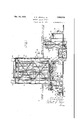
- Figure 1 is a side elevation of apparatus embodying the invention, in its preferred form, a part thereof being broken away for clearness of illustration
- Figure 2 is a plan view of the uniform tension mechanism at the work receiving end of the apparatus;
- Figure 3 is a section on the line 3-3 of Fig-. ure 2;
- Figure 4 is a section on the line 4-4 of Figure 3;
- Figure 5 is an elevation of fabric-rewind mechanism at the work-delivery end of the machine.
- Figure 6 is a plan view of the apparatus shown in Figure 5.
- I0 is a vertically arranged, tall, tubular housing within which is mounted an open framework II that carries a plurality of work supporting rollers l2, I2 journaled at the top thereof.
- a container l6 filled with liquid rubber composition consisting of rubber dissolved in a hydrocarbon solvent, and the fabric I5 is guided through said liquid composition by means of guide-rollers l1, l1.
- Said container also includes a pair of squeeze-rolls l8, l8 located above the level of the liquid and through which the fabric 15 is drawn to remove excess impregnating composition therefrom.
- the liquid in the container l6 constitutes a seal to prevent the escape of a work drying medium in the housing It), and the level of said liquid is kept substantially constant by mechanism that automatically and periodically admits liquid into said container, said mechanism being controlled by a valve 19.
- a seal of known construction through which the fabric I5 is withdrawn from said housing said seal also serving to wipe loose lumps of rubher from said fabric.
- the fabric 15 is fed through the housing or drying chamber II] at a constant, uniform speed, and to this end the adjacent ends of the shafts of the several rollers l4 and the roller 22 are provided with suitable sprockets about which is trained a sprocket chain 24, the latter also passing about an idler sprocket 25, and about a sprocket on a power driven shaft 26.
- a second sprocket or shaft 26 is connected by a sprocket chain 2! with an electric motor (not shown), and a third sprocket on said shaft 26 is connected by a sprocket chain 26 with a sprocket on the shaft 3a of one of the squeeze-rolls I6.
- a second sprocket on the shaft l8a is connected by a sprocket chain 29 with a sprocket on the shaft 36 of a feed roller 3
- an inert gas such as carbon dioxide gas
- the inert gas is conducted into the housing through pipe 36 that is connected with a suitable source of supply (not shown) of said gas, said pipe discharging into an elongate manifold 31 that surrounds the last festoon of fabric, said manifold discharging into the housing chamber at its up per end.
- the gaseous mixture of carbon dioxide and solvent vapor is withdrawn from the housing chamber at a point diametrically opposite the gas inlet, and conducted to a suitable apparatus (not shown) where the solvent is recovered from the mixture.
- a suction fan 38 positioned outside the housing has connection with the, said recover-y apparatus through pipe 39, and has connection with the interior of the housing through pipe 40 that extends through the wall of the latter.
- a suitable baflie 4i is positioned in front of the inlet to pipe 40 to prevent the fabric l5 from being drawn thereinto.
- the rate of inflow of carbon dioxide and the rate at which the mixture is withdrawn are so coordinated that the mixture within the housing is at low super-atmospheric pressure.
- the arrangement is such that in case of leakage of the housing there will be an escape of the mixture therefrom rather than the admission of air thereinto, thus avoiding the possibility of creating an explosive mixture in the housing.
- vents 42, 42 Excessive pressure in the housing chamber is prevented by the provision of a pair of vents 42, 42 at the top thereof, said vents being provided with water-sealed relief valves (not shown).
- the housing may also be provided with weak explosion panels 43, 43 at the top thereof.
- the apparatus for applying tension to the fabric l5, at the work-receiving end of the apparatus comprises an open framework 45 that is positioned at the receiving side of fabric drier 32, there being a smaller, subsidiary framework 46 associated with framework 45 on the. side thereof that is remote from said drier.
- Mounted upon the framework 46 is a pair of bearing brackets 41, 41 in which are journaled respective spindles 46 for receiving and supporting a square axial bar 43 that carries a supply roll 56 of the fabric l5.
- is mounted upon one of the spindles 48, and a weighted brake band 52 engages said brake drum for preventing rotation of supply roll 56 except when the fabric I 5 is pulled therefrom.
- Fabric is withdrawn from the supply roll by a pair of driven feed rollers 53, 54 that are suitably journaled in the upper part of framework 46.
- a guide-roller 55 journaled on the framework 46, below the said feed rollers, the rollers 54, 55 being so arranged with relation to roller 53 as to guide the fabric 15 about roller 53 in engagement with about three-fourths of the surface of the latter, whereby good driving friction between the roller and the fabric is assured.
- Feed rollers 53, 54 are geared together by meshed gears 56, 51 so that they are driven in unison, and the shaft 53a of roller 53 is coupled to the shaft of an electric motor 56 suitably supported in the upper part of framework 46.
- the speed of the electric motor 58 is controlled by a rheostat that is located in a sealed box 56 that is mounted upon framework 45, and the operation of the rheostat is effected by fabric-storage means carried by said framework, as presently will be explained.
- Journaled in the top of framework 45 is a plurality of horizontal, fabric-supporting rollers 6
- the arrangement is such that the fabric strip l5 when passed over the rollers 6
- tentering roller 64 On the work-receiving side of framework 45, at an intermediate height thereon, is journaled a tentering roller 64 of the well-known type having a right hand and left hand raised rib on its surface, the fabric I5 passing about said rolller 64 as it moves from the guide roller 55 to the adjacent festoon roller 6
- a similar tentering roller 65 is journaled on the framework 45 at the work-delivery side thereof and guides the outgoing fabric from the last festoon roller 6
- the floating frame 62 is provided at its opposite sides with respective, vertically disposed brackets 66, 68, and each of the latter has a disc-roller 69 journaled in its opposite ends, as is most clearly shown in Figure 4.
- the disc-rollers 66 on the respective brackets engage in a channeled or angular vertical guide 10, which guides are secured to the framework 45 on opposite sides thereof.
- Connected to the upper ends of the respective brackets 66 are respective sprocket chains H, II, which sprocket chains extend to the top of the framework and'pass over respective-sprockets I2, the free end of each chain being connected to a counterweight I3.
- the weight of the latter may be varied, and optimum condition obtains when the floating frameis slightly heavier than its counterweights, so that it will sink by gravity and draw fabric into the festoons when the input of fabric from the supply roll 56 is greater than the outgo to the drier 32. Conversely, the floating frame easily is lifted without imposing any considerable strain on the fabric when the fabric is withdrawn from the festoons faster than it is fed thereinto, which condition obtains when the motor 56 is stopped to permit an exhausted supply roll to be replaced by a new supply roll 56 of fabric.
- the shaft 63a ( Figure 3) upon which the middle roller 63 is journaled is itself journaled in the frame 62, and has sprockets 15, 15 mounted upon its respective end portions adjacent the ends of said roller 63.
- sprockets I5, above and below the same sprockets I6, I8 are journaled upon the respective brackets 68.
- the sprockets I5 are engaged by respective vertically disposed sprocket chains 11, 11 that are fixedly secured to the floor and to the top of framework 45, the sprockets I6 serving to guide the chains about said sprockets I5 and hold them thereagainst.
- the arrangement is such that any movement of the floating frame 62 at either end thereof will cause rotation of shaft 63a and thereby cause concurrent movement of the other end of the frame by reason of the movement of sprocket I5 along sprocket chain II, with the result that the floating frame always maintains its horizontal position.
- One of the sprockets I2 aforementioned is mounted upon a stub shaft 19 that is journaled in a bearing bracket 80 upon the top of framework 45.
- the other sprocket i2 is mounted upon one end of a shaft 8
- the arrangement is such that while the floating frame 62 is rising the rheostat shaft 86 is slowly rotated to effect a speeding up of the motor 58, the speed of said motor being progressively slowed down by the downward movement of the floating frame.
- the speed of motor 58 is in direct proportion to-the ratio of outfeed to infeed of fabric into the storage mechanism comprising the festoons and floating frame.
- a limit switch 88 that is electrically connected to the motor 58 for stopping the same.
- another limit switch 89 that is electrically connected to the motor (not shown) that drives the festoons of impregnated fabric within the housing I0.
- the operating arms of switches 88, 89 extend into the paths of a pair of cams 98, 9
- the arrangement is such that when the storage festoons are substantially full the motor 58 automatically is stopped so as to discontinue the infeed of fabric, and when the fabric is substantially all withdrawn from the festoons the motor that withdraws it therefrom automatically is stopped.
- the rate of the infeeding of fabric into the storage festoons is substantially the same as the speed of withdrawalstherefrom when the floating frame 62 is near the bottom of its course of travel, as shown in the drawings.
- Any differential of infeed and outfeed such as would cause the said floating frame to rise or fall operates the rheostat within the box 59 and ,thus correspondingly speeds up or slows down the motor 58 until equilibrium again is effected;
- bracket 95 that carries a pair of tacky gum-spot rollers 96, 96 in the top thereof, which rollers are angularly adjustable as a unit to vary the tension of the fabric passing about them.
- the function of the rollers 96 is to engage opposite faces of the impregnated fabric I5 and to remove gum-spots or loose strands of lint therefrom.
- the bracket 95 also carries a spreader roll 9'! near its base and about which the fabric is drawn.
- the impregnated fabric I5 is wound into a roll I upon a rewinding shell I8 I, the latter being driven by an electric motor I02.
- a fabric storage device Associated with the rewinding apparatus, between the latter and the housing I8 is a fabric storage device that is substantially identical with that previously described at the opposite end of the apparatus, so that only a brief description thereof will suflice.
- Said storage device comprises an open framework I04, a series of stationarily journaled rollers I85, I at. the top thereof, a floating frame I06, and a series of rollers I01, I01 journaled on said floating frame, the impregnated fabric I5 passing over the rollers I05 and under the rollers I01 in a succession of festoons.
- the floating frame I06 rises and falls accordingly as the fabric is withdrawn from the festoons onto the rewinding shell IOI at a greater or lesser speed than it is fed into the festoons after delivery from the housing I0.
- This vertical movement of the floating frame I06 is utilized for operating a rlieostat (not shown) that is mounted in a sealed box I 00 on the framework I 04, the mechanism connecting the floating frame with the said rheostat being identical with that provided for the same purpose at the opposite end of the apparatus.
- the said rheostat controls the speed of the motor I02, the arrangement being such that the speed of the motor is slowed down as the floating frame rises and accelerated as the said frame sinks.
- Associated with the storage device is a lower limit switch I I0 adapted to be operated by the floating frame I06 at the lowermost limit of its range of travel, and an upper limit switch III operable by said floating frame at the uppermost limit of its range of travel. Operation of limit switch IIO stops the motor (not shown) that drives the festoons of impregnated fabric within the housing I0. Operation of limit switch III stops motor I02.
- the floating frame In the operation of the storage means de scribed at the delivery end of the apparatus, the floating frame normally occupies a position near its uppermost limit of travel, as shown in Figure 1, the fabric being withdrawn from the festoons substantially at the same rate that it is being drawn thereinto.
- the motor I02 When the rewind shell IOI is full of finished fabric, the motor I02 is manually stopped, the roll of fabric I00 is removed from the machine and replaced by an empty shell IOI, the end of the continuous strip of fabric I5 is started onto the empty shell, and the motor I02 manually started.
- fabric from the housing I0 is being drawn into the storage festoons by the weight of the floating frame I06, the latter moving downwardly.
- the rewinding shell IN is mounted upon a square shaft II3 that is removably supported at its respective ends in spindles III, Ill that are journaled in the outer ends of respective bracket arms II5, II5 that are pivotally mounted at H5, H5 upon respective brackets III, III.
- One of the spindles Ill is coupled at II8 to the driving shaft of motor I02 that is axially aligned therewith, said motor being mounted upon the outer end of a bracket arm II9 that is pivotally mounted at I20 upon a bracket I2I.
- bracket arms H5, H5, and H9 have extensions rearwardly of their respective pivots, which extensions are pivotally connected by a link I22.
- the arrangement constituting a parallel motion mechanism whereby the rewinding shell IOI and motor I02 may be moved axially as a unit to center the shell with relation to the fabric I5 being delivered thereto.
- a laterally projecting angular arm I20 is mounted upon the bracket III that is farthest from motor I02, the free end of said arm having a nut I20 swivelled on the top face thereof.
- a similar nut I25 having opposite hand threads is swivelled on the top face ofadjacent bracket arm II5.
- a screw I25 formed with right and left-hand threads is threaded through the respective nuts I24, I25, and is provided in its medial region with a hand wheel I21 whereby it may be manually turned, whereby the bracket arm H5 is moved angularly and the position of the rewinding shell IOI is altered.
- a segmental spreader roll I20 of well-known construction adapted fully to spread the fabric before the latter passes onto the shell IOI.
- Said spreader roll is provided with the usual adjusting means controlling the extent of its spreading effect upon the fabric, said adjusting means including a rotatable post I20 that is provided with a handwheel I3I.
- a guide roller I02 is associated with the spreader roll I20 for limiting the area of engagement between the spreader roll and the fabric.
- a guide roller I over which the fabric moves in passing from guide roller I22 to the shell "I.
- a weighted eccentric I35 Pivotally mounted above guide roller I 20 is a weighted eccentric I35 that rests upon the fabric I5 passing over roller I.
- the arrangement is such that the fabric may be drawn under the eccentric in one direction, that is, in moving toward the rewind shell IOI. Any recession of the fabric causes the eccentric to move angularly and bind against the roller I24 thus pinching the fabric thereon and preventing further recession of the fabric.
- the arrangement prevents the end of the fabric from being pulled backward during the interval that a full shell of fabric is being removed from the apparatus and an empty shell placed therein.
- the fabric I5 may be fed continuously through the impregnating composition in container I5 and through the drying chamber in housing I0 without such stopping as would cause the fabric to adhere to the guide rollers therein and thus cause damaging irregularities in the coating of the fabric.
- the feature of mounting the rheostats in sealed boxes makes for safety since there may be vaporized solvent about the apparatus, and any sparks in such atmosphere would be dangerous. For this reason the several motors used with the apparatus are of a special type known as sparkless.
- the invention results in substantial savings by avoiding the production of damaged fabric, the fabric produced is of uniform stretch and quality, and the other objects set out in the foregoing statement of objects are achieved.
- a fabric storage device comprising a series of flxed rollers, and a series of rollers upon a horizontal, vertical- 1y movable floating frame, said rollers supporting a continuous strip of fabric in a plurality of festoons, means for feeding fabric into said festoons, means for withdrawing fabric from said festoons, and means for maintaining said floating frame in horizontal position, said means engaging opposite ends of a shaft on said floating frame, on which shaft one of the rollerson said floating frame is mounted.
- a fabric storage device comprising a series of fixed rollers, and a series of rollers upon a horizontal, vertically movable floating frame, said rollers supporting a continuous strip of fabric in a plurality of festoons, means for feeding fabric into said festoons periodically, means for withdrawing fabric from said festoons continuously, and means for maintaining said floating frame in horizontal position, said means comprising sprockets mounted upon opposite ends of a shaft on said floating frame, on which shaft one of the rollers on said floating frame is mounted, and respective sprocket chains with which said sprockets are engaged.
Description
NOV. 24, 1936., LEWIS ET AL 2,062,008
UNIFORM TENSION DEVICE Filed July 51, 1955 5 Sheets-Sheet l INVENTOR Aflhur P. Lewis 15 WilYmm 5. 5e 51' TORNEY Nov. 24, 1936. A. P. LEWIS ET AL 2,062,008
UNIFORM TENSION DEVICE Filed July 51, 1935 5 Sheets-Sheet 2 ATTOR Y UNIFORM TENS ION DEVICE Filed July 31, 1935 5 Sheets-Sheet 3 51 SZ (1" i e9 j r 72 ,1 MWW////fW// s a 6'5 ,3 1 1 63 "I 69 INVENTOR Arthur P. Lewis 5? William S- SQGrQS 4 W TTORNEY Nov; 24, 1936. A. P. LEWIS ET AL UNIFORM TENSION DEVICE Filed July 51, 1935 m T N E V m Arthur PLewis-E:
|| I' N H 0 ||||||ll||| ||||||I min I h I 1.. 0 4
5 Sheets-Sheet 4 5ec bi" ATT Nov. 24, 1936. A. P. LEWIS ET AL,
UNIFORM TENSION DEVICE Filed July 51, 1955 5 Sheets-Sheet 5 INVENTOR ATTO Patented Nov. 24, 1936 PATENT OFFICE UNIFORM TENSION DEVICE Arthur P. Lewis, Fair Haven, Mass and William J. Secrest, Cuyahoga Falls, Ohio, assignors to The Firestone Tire &
Rubber Company, Akron,
Ohio, a corporation of Ohio Application July 31,
2 Claims.
This invention relates to uniform tension devices, and more especially it relates to devices for maintaining a constant uniform tension in continuous'strip material that is unwound fro! one roll thereof, treated or processed while oil! said roll, and then rewound upon another roll.
The invention is of major importance in the rubber industry, for example, in apparatus for processing tire building fabric. In a method of preparing rubberized, weak-wefted cord fabric for tire casingsthat comprises initially impregnating the cords of the fabric with rubber composition in solution, there is provided impregnating apparatus-comprising a bath of viscous rubber composition, and a drying chamber through which the impregnated fabric passes, the feed of the fabric being constant. Fabric to be impregnated is withdrawn from a roll of the fabric, and since this roll becomes exhausted and requires to be replaced by a new roll, suitable fabric-storage means is provided between the supply roll and the drying chamber so that fabric may be withdrawn from the storage means during the interval required for replacing'an exhausted supply roll with a fresh one. In like manner a fabric-storage means is positioned at the work-delivery end of the apparatus for receiving and storing fabric from the drying chamber during the intrgal required to remove 30 .a full roll of impregnat fabric and replace it with an empty roll-she Both the fabric supply roll at the work-receiving end of the apparatus and the rewinding roll at the work-delivery end of the apparatus are power driven, and, because said rolls vary in diameter as fabric is removed therefrom or Wound thereon, it is necessary to provide means for constantly adjusting the speed of rotation of said rolls in; order to maintain a constant uniform tension on the fabric. The means by which the speed of rotation of said fabric rolls automatically is adjusted constitutes the subject matter of this invention.
The chief objects of the invention are to produce processed tire fabric of uniform quality; to produce tire fabric of determinate stretch and crimp; to obviate mis-cuts in the subsequent cutting of continuous tire fabric into tire-building plies; and to avoid waste of tire fabric from causes arising from improper processing. More specifically the invention aims to provide means by which continuous tire building fabric may be rubber-impregnated while under constant, uniform, determinate tension. Other objects will be manifest.
1935, Serial No. 33,994
Of the accompanying drawings:
Figure 1 is a side elevation of apparatus embodying the invention, in its preferred form, a part thereof being broken away for clearness of illustration Figure 2 is a plan view of the uniform tension mechanism at the work receiving end of the apparatus;
Figure 3 is a section on the line 3-3 of Fig-. ure 2;
Figure 4 is a section on the line 4-4 of Figure 3;
Figure 5 is an elevation of fabric-rewind mechanism at the work-delivery end of the machine; and
Figure 6 is a plan view of the apparatus shown in Figure 5.
Referring now to Figure 1 of the drawings, I0 is a vertically arranged, tall, tubular housing within which is mounted an open framework II that carries a plurality of work supporting rollers l2, I2 journaled at the top thereof. Mounted in suitable receptacles l3, that are secured to the bottom of the housing 10 and open to the interior of the latter, are respective work-driving rollers 14, H, the work, consisting of a continu ous strip of weak-wefted cord fabric I5, being threaded in alternation over the rollers l2 and under the rollers 14 is a plurality of festoons. At the work receiving end of the apparatus is a container l6 filled with liquid rubber composition consisting of rubber dissolved in a hydrocarbon solvent, and the fabric I5 is guided through said liquid composition by means of guide-rollers l1, l1. Said container also includes a pair of squeeze-rolls l8, l8 located above the level of the liquid and through which the fabric 15 is drawn to remove excess impregnating composition therefrom. The liquid in the container l6 constitutes a seal to prevent the escape of a work drying medium in the housing It), and the level of said liquid is kept substantially constant by mechanism that automatically and periodically admits liquid into said container, said mechanism being controlled by a valve 19. At the work-delivery end of the housing 10 is a seal of known construction through which the fabric I5 is withdrawn from said housing said seal also serving to wipe loose lumps of rubher from said fabric. Immediately outside the seal 20 are guide rollers 2|, 2|, and a feed roller 22 about which the work passes.
The fabric 15 is fed through the housing or drying chamber II] at a constant, uniform speed, and to this end the adjacent ends of the shafts of the several rollers l4 and the roller 22 are provided with suitable sprockets about which is trained a sprocket chain 24, the latter also passing about an idler sprocket 25, and about a sprocket on a power driven shaft 26. A second sprocket or shaft 26 is connected by a sprocket chain 2! with an electric motor (not shown), and a third sprocket on said shaft 26 is connected by a sprocket chain 26 with a sprocket on the shaft 3a of one of the squeeze-rolls I6. A second sprocket on the shaft l8a is connected by a sprocket chain 29 with a sprocket on the shaft 36 of a feed roller 3| that is associated with a fabric drier 32 at the work-receiving end of the apparatus, said drier comprising rotatable, steam heated drums or cylinders 33, 33 about which the fabric is drawn by said feed roller.
Interiorly of the housing III are steam-heated coils 35, 35 that are suitably arranged between the festoons of fabric and serve to volatilize the solvent in the composition with which the fabric is impregnated. In order to prevent the solvent vapor from forming an explosive mixture in the housing In, an inert gas, such as carbon dioxide gas, is introduced thereinto. To this end the inert gas is conducted into the housing through pipe 36 that is connected with a suitable source of supply (not shown) of said gas, said pipe discharging into an elongate manifold 31 that surrounds the last festoon of fabric, said manifold discharging into the housing chamber at its up per end. The gaseous mixture of carbon dioxide and solvent vapor is withdrawn from the housing chamber at a point diametrically opposite the gas inlet, and conducted to a suitable apparatus (not shown) where the solvent is recovered from the mixture.
For withdrawing the mixture from the housing, a suction fan 38 positioned outside the housing has connection with the, said recover-y apparatus through pipe 39, and has connection with the interior of the housing through pipe 40 that extends through the wall of the latter. A suitable baflie 4i is positioned in front of the inlet to pipe 40 to prevent the fabric l5 from being drawn thereinto. The rate of inflow of carbon dioxide and the rate at which the mixture is withdrawn are so coordinated that the mixture within the housing is at low super-atmospheric pressure. The arrangement is such that in case of leakage of the housing there will be an escape of the mixture therefrom rather than the admission of air thereinto, thus avoiding the possibility of creating an explosive mixture in the housing. Excessive pressure in the housing chamber is prevented by the provision of a pair of vents 42, 42 at the top thereof, said vents being provided with water-sealed relief valves (not shown). The housing may also be provided with weak explosion panels 43, 43 at the top thereof.
The apparatus for applying tension to the fabric l5, at the work-receiving end of the apparatus, comprises an open framework 45 that is positioned at the receiving side of fabric drier 32, there being a smaller, subsidiary framework 46 associated with framework 45 on the. side thereof that is remote from said drier. Mounted upon the framework 46 is a pair of bearing brackets 41, 41 in which are journaled respective spindles 46 for receiving and supporting a square axial bar 43 that carries a supply roll 56 of the fabric l5. A brake drum 5| is mounted upon one of the spindles 48, and a weighted brake band 52 engages said brake drum for preventing rotation of supply roll 56 except when the fabric I 5 is pulled therefrom. Fabric is withdrawn from the supply roll by a pair of driven feed rollers 53, 54 that are suitably journaled in the upper part of framework 46. There is a guide-roller 55 journaled on the framework 46, below the said feed rollers, the rollers 54, 55 being so arranged with relation to roller 53 as to guide the fabric 15 about roller 53 in engagement with about three-fourths of the surface of the latter, whereby good driving friction between the roller and the fabric is assured.
Journaled in the top of framework 45 is a plurality of horizontal, fabric-supporting rollers 6|, 6|, herein shown as four in number, and vertically movable within said framework is a floating frame 62 which carries three rollers 63, 63 that are disposed in the same horizontal plane and are journaled on respective shafts carried by the floating frame. The arrangement is such that the fabric strip l5 when passed over the rollers 6| and under the rollers 63, in a series of festoons, will support the floating frame 62, and the elevation of said floating frame will be governed by the amount of fabric in said festoons. On the work-receiving side of framework 45, at an intermediate height thereon, is journaled a tentering roller 64 of the well-known type having a right hand and left hand raised rib on its surface, the fabric I5 passing about said rolller 64 as it moves from the guide roller 55 to the adjacent festoon roller 6|. A similar tentering roller 65 is journaled on the framework 45 at the work-delivery side thereof and guides the outgoing fabric from the last festoon roller 6| of the series to a tentering roller 66 associated with the drier 32.
The floating frame 62 is provided at its opposite sides with respective, vertically disposed brackets 66, 68, and each of the latter has a disc-roller 69 journaled in its opposite ends, as is most clearly shown in Figure 4. The disc-rollers 66 on the respective brackets engage in a channeled or angular vertical guide 10, which guides are secured to the framework 45 on opposite sides thereof. Connected to the upper ends of the respective brackets 66 are respective sprocket chains H, II, which sprocket chains extend to the top of the framework and'pass over respective-sprockets I2, the free end of each chain being connected to a counterweight I3. The weight of the latter may be varied, and optimum condition obtains when the floating frameis slightly heavier than its counterweights, so that it will sink by gravity and draw fabric into the festoons when the input of fabric from the supply roll 56 is greater than the outgo to the drier 32. Conversely, the floating frame easily is lifted without imposing any considerable strain on the fabric when the fabric is withdrawn from the festoons faster than it is fed thereinto, which condition obtains when the motor 56 is stopped to permit an exhausted supply roll to be replaced by a new supply roll 56 of fabric.
In order to prevent the floating frame 62 from u tilting so that one end of the rollers 63 thereof is higher than the other end, the shaft 63a (Figure 3) upon which the middle roller 63 is journaled is itself journaled in the frame 62, and has sprockets 15, 15 mounted upon its respective end portions adjacent the ends of said roller 63. In vertical alignment with sprockets I5, above and below the same, sprockets I6, I8 are journaled upon the respective brackets 68. The sprockets I5 are engaged by respective vertically disposed sprocket chains 11, 11 that are fixedly secured to the floor and to the top of framework 45, the sprockets I6 serving to guide the chains about said sprockets I5 and hold them thereagainst. The arrangement is such that any movement of the floating frame 62 at either end thereof will cause rotation of shaft 63a and thereby cause concurrent movement of the other end of the frame by reason of the movement of sprocket I5 along sprocket chain II, with the result that the floating frame always maintains its horizontal position.
- One of the sprockets I2 aforementioned is mounted upon a stub shaft 19 that is journaled in a bearing bracket 80 upon the top of framework 45. The other sprocket i2 is mounted upon one end of a shaft 8| that is journaled in a pair of spaced brackets 82, 82, there being a sprocket 83 mounted'upon the other end of shaft 8| and connected by sprocket chain 84 to a sprocket 85 on the rotatable shaft 86 of the rheostat within the sealed box 59, said shaft projecting from the front of said box. The arrangement is such that while the floating frame 62 is rising the rheostat shaft 86 is slowly rotated to effect a speeding up of the motor 58, the speed of said motor being progressively slowed down by the downward movement of the floating frame. Thus the speed of motor 58 is in direct proportion to-the ratio of outfeed to infeed of fabric into the storage mechanism comprising the festoons and floating frame.
Near the bottom of framework 45 is a limit switch 88 that is electrically connected to the motor 58 for stopping the same. Near the top of framework 45 is another limit switch 89 that is electrically connected to the motor (not shown) that drives the festoons of impregnated fabric within the housing I0. The operating arms of switches 88, 89 extend into the paths of a pair of cams 98, 9| that are mounted upon the floating frame 62 and are adapted to engage and actuate the operating arms of the respective switches 88, 89, when the floating frame is at its lowermost position as shown in full lines in Fig. 3, or at its uppermost position as shown in broken lines in the same figure. The arrangement is such that when the storage festoons are substantially full the motor 58 automatically is stopped so as to discontinue the infeed of fabric, and when the fabric is substantially all withdrawn from the festoons the motor that withdraws it therefrom automatically is stopped.
In the normal operation of the apparatus previously described, the rate of the infeeding of fabric into the storage festoons is substantially the same as the speed of withdrawalstherefrom when the floating frame 62 is near the bottom of its course of travel, as shown in the drawings. Any differential of infeed and outfeed such as would cause the said floating frame to rise or fall operates the rheostat within the box 59 and ,thus correspondingly speeds up or slows down the motor 58 until equilibrium again is effected;
When the fabric in supply roll 58 is exhausted, the motor 58 is manually stopped, .the friction between the fabric and feed rollers 53, 54 preventing any more of the fabric being drawn into the storage festoons by the weight of the floating frame 82. The outfeed from said festoons is continuous, and when the infeed of fabric stops as described, said outfeed gradually depletes the festoons and lifts the floating frame. Usually the time required to lift the floating frame to the top of framework 45 is sufiicient to permit the removal of the exhausted roll-shell, the mounting of a fresh supply roll of fabric, and the connecting of the leading end of the fabric of said roll to the trailing end of the fabric of the preceding roll. If the latter operations require too much time, the outfeeding of the fabric will stop when the floating frame 62 operates the upper limit switch 89. When the motor 58 again is started, its speed, due'to the position of the floating frame, is such that the fabric is fed into the storage festoons at greater lineal speed than it is withdrawn therefrom, with the result that the floating frame gradually moves downward by gravity. This progressively slows down the speed of motor 58 until equilibrium once more is established as the floating frame approaches its lowermost position. The fabric withdrawn from the storage festoons is drawn continuously through the impregnating composition in container I6 and through the chamber in housing I8 as previously described.
At the work-delivery end of the housing I8, below the same, is a bracket 95 that carries a pair of tacky gum-spot rollers 96, 96 in the top thereof, which rollers are angularly adjustable as a unit to vary the tension of the fabric passing about them. The function of the rollers 96 is to engage opposite faces of the impregnated fabric I5 and to remove gum-spots or loose strands of lint therefrom. The bracket 95 also carries a spreader roll 9'! near its base and about which the fabric is drawn. There is a guide roller 98 journaled on the supporting structure of housing I8 about which the fabric passes after passing about spreader roll 91.
At the work-delivery end of the apparatus the impregnated fabric I5 is wound into a roll I upon a rewinding shell I8 I, the latter being driven by an electric motor I02. Associated with the rewinding apparatus, between the latter and the housing I8 is a fabric storage device that is substantially identical with that previously described at the opposite end of the apparatus, so that only a brief description thereof will suflice.
Said storage device comprises an open framework I04, a series of stationarily journaled rollers I85, I at. the top thereof, a floating frame I06, and a series of rollers I01, I01 journaled on said floating frame, the impregnated fabric I5 passing over the rollers I05 and under the rollers I01 in a succession of festoons. There is a spreader roll I08 journaled on framework I04 at an intermediate position for guiding the fabric I5 from the guide roller 98 aforementioned to the nearest festoon roller I05, and a similar spreader roller I08a is journaled on the opposite side of the framework for engagement with the fabric after the latter passes from the last of the series of festooning rollers I05. The floating frame I06 rises and falls accordingly as the fabric is withdrawn from the festoons onto the rewinding shell IOI at a greater or lesser speed than it is fed into the festoons after delivery from the housing I0.
This vertical movement of the floating frame I06 is utilized for operating a rlieostat (not shown) that is mounted in a sealed box I 00 on the framework I 04, the mechanism connecting the floating frame with the said rheostat being identical with that provided for the same purpose at the opposite end of the apparatus. The said rheostat controls the speed of the motor I02, the arrangement being such that the speed of the motor is slowed down as the floating frame rises and accelerated as the said frame sinks. Associated with the storage device is a lower limit switch I I0 adapted to be operated by the floating frame I06 at the lowermost limit of its range of travel, and an upper limit switch III operable by said floating frame at the uppermost limit of its range of travel. Operation of limit switch IIO stops the motor (not shown) that drives the festoons of impregnated fabric within the housing I0. Operation of limit switch III stops motor I02.
In the operation of the storage means de scribed at the delivery end of the apparatus, the floating frame normally occupies a position near its uppermost limit of travel, as shown in Figure 1, the fabric being withdrawn from the festoons substantially at the same rate that it is being drawn thereinto. When the rewind shell IOI is full of finished fabric, the motor I02 is manually stopped, the roll of fabric I00 is removed from the machine and replaced by an empty shell IOI, the end of the continuous strip of fabric I5 is started onto the empty shell, and the motor I02 manually started. During the interval required to remove the full shell IOI and replace it with an empty shell, fabric from the housing I0 is being drawn into the storage festoons by the weight of the floating frame I06, the latter moving downwardly. Usually there is ample time to mount the empty shell IOI in the apparatus before the floating frame reaches the lowermost limit of its movement. The downward movement of the floating frame turns the rheostat in box I09 so that when the motor I02 again is started, it rotates at accelerated speed suiilcient to withdraw fabric from the storage device slightly faster than it is drawn thereinto, thus causing the floating frame I06 to rise.
The fact that the roll of rewound fabric I00 constantly increases in diameter also tends to increase the speed at which fabric is withdrawn from the storage device. Opposed to said speedincreasing factors is the rheostat in box I00 which automatically is turned by the rising floating frame so as constantly to diminish the speed of the motor. I02. Where said floating frame is adjacent the uppermost limit of its course of travel, the outgoing lineal speed of the fabric in the storage device is substantially equal to its incoming speed.
Details of the fabric-rewinding mechanism are shown in Figures 5 and 6 of the drawings to which attention now is directed. The rewinding shell IN is mounted upon a square shaft II3 that is removably supported at its respective ends in spindles III, Ill that are journaled in the outer ends of respective bracket arms II5, II5 that are pivotally mounted at H5, H5 upon respective brackets III, III. One of the spindles Ill is coupled at II8 to the driving shaft of motor I02 that is axially aligned therewith, said motor being mounted upon the outer end of a bracket arm II9 that is pivotally mounted at I20 upon a bracket I2I. The bracket arms H5, H5, and H9 have extensions rearwardly of their respective pivots, which extensions are pivotally connected by a link I22. the arrangement constituting a parallel motion mechanism whereby the rewinding shell IOI and motor I02 may be moved axially as a unit to center the shell with relation to the fabric I5 being delivered thereto. For so moving the said shell and motor axially, a laterally projecting angular arm I20 is mounted upon the bracket III that is farthest from motor I02, the free end of said arm having a nut I20 swivelled on the top face thereof. A similar nut I25 having opposite hand threads is swivelled on the top face ofadjacent bracket arm II5. A screw I25 formed with right and left-hand threads is threaded through the respective nuts I24, I25, and is provided in its medial region with a hand wheel I21 whereby it may be manually turned, whereby the bracket arm H5 is moved angularly and the position of the rewinding shell IOI is altered.
Journaled between the brackets III, in position to engage the fabric I5 as it comes from roller I00 on the framework I04, is a segmental spreader roll I20 of well-known construction adapted fully to spread the fabric before the latter passes onto the shell IOI. Said spreader roll is provided with the usual adjusting means controlling the extent of its spreading effect upon the fabric, said adjusting means including a rotatable post I20 that is provided with a handwheel I3I. A guide roller I02 is associated with the spreader roll I20 for limiting the area of engagement between the spreader roll and the fabric.
Journaled atop of the brackets III is a guide roller I over which the fabric moves in passing from guide roller I22 to the shell "I. Pivotally mounted above guide roller I 20 is a weighted eccentric I35 that rests upon the fabric I5 passing over roller I. The arrangement is such that the fabric may be drawn under the eccentric in one direction, that is, in moving toward the rewind shell IOI. Any recession of the fabric causes the eccentric to move angularly and bind against the roller I24 thus pinching the fabric thereon and preventing further recession of the fabric. The arrangement prevents the end of the fabric from being pulled backward during the interval that a full shell of fabric is being removed from the apparatus and an empty shell placed therein.
From the foregoing description it will be seen that the fabric I5 may be fed continuously through the impregnating composition in container I5 and through the drying chamber in housing I0 without such stopping as would cause the fabric to adhere to the guide rollers therein and thus cause damaging irregularities in the coating of the fabric. The feature of mounting the rheostats in sealed boxes makes for safety since there may be vaporized solvent about the apparatus, and any sparks in such atmosphere would be dangerous. For this reason the several motors used with the apparatus are of a special type known as sparkless.
The invention results in substantial savings by avoiding the production of damaged fabric, the fabric produced is of uniform stretch and quality, and the other objects set out in the foregoing statement of objects are achieved.
Modification may be resorted to without departing from the spirit of the invention or the scope of the appended claims.
What is claimed is:
1. In uniform tension apparatus, a fabric storage device comprising a series of flxed rollers, and a series of rollers upon a horizontal, vertical- 1y movable floating frame, said rollers supporting a continuous strip of fabric in a plurality of festoons, means for feeding fabric into said festoons, means for withdrawing fabric from said festoons, and means for maintaining said floating frame in horizontal position, said means engaging opposite ends of a shaft on said floating frame, on which shaft one of the rollerson said floating frame is mounted.
2. In uniform tension apparatus, a fabric storage device comprising a series of fixed rollers, and a series of rollers upon a horizontal, vertically movable floating frame, said rollers supporting a continuous strip of fabric in a plurality of festoons, means for feeding fabric into said festoons periodically, means for withdrawing fabric from said festoons continuously, and means for maintaining said floating frame in horizontal position, said means comprising sprockets mounted upon opposite ends of a shaft on said floating frame, on which shaft one of the rollers on said floating frame is mounted, and respective sprocket chains with which said sprockets are engaged. 10
ARTHUR P. LEWIS. WILLIAM J. SECREST.
Priority Applications (1)
| Application Number | Priority Date | Filing Date | Title |
|---|---|---|---|
| US33994A US2062008A (en) | 1935-07-31 | 1935-07-31 | Uniform tension device |
Applications Claiming Priority (1)
| Application Number | Priority Date | Filing Date | Title |
|---|---|---|---|
| US33994A US2062008A (en) | 1935-07-31 | 1935-07-31 | Uniform tension device |
Publications (1)
| Publication Number | Publication Date |
|---|---|
| US2062008A true US2062008A (en) | 1936-11-24 |
Family
ID=21873668
Family Applications (1)
| Application Number | Title | Priority Date | Filing Date |
|---|---|---|---|
| US33994A Expired - Lifetime US2062008A (en) | 1935-07-31 | 1935-07-31 | Uniform tension device |
Country Status (1)
| Country | Link |
|---|---|
| US (1) | US2062008A (en) |
Cited By (12)
| Publication number | Priority date | Publication date | Assignee | Title |
|---|---|---|---|---|
| US2448835A (en) * | 1945-01-30 | 1948-09-07 | Carnegie Illinois Steel Corp | Apparatus for continuously processing strips |
| US2481992A (en) * | 1945-02-23 | 1949-09-13 | Earl J Fisher | Method and apparatus for continuous run treatment of sheet materials |
| US2688453A (en) * | 1949-07-07 | 1954-09-07 | Western Electric Co | Strip winding apparatus |
| US2771984A (en) * | 1951-05-16 | 1956-11-27 | Wean Equipment Corp | Mechanism for handling elongated material |
| US2809828A (en) * | 1955-03-21 | 1957-10-15 | Technicolor Corp | Cinematographic film processing |
| US2995181A (en) * | 1956-03-08 | 1961-08-08 | Us Rubber Co | Method and apparatus for uniting sheets of resilient material |
| US3233808A (en) * | 1962-11-08 | 1966-02-08 | Ind Ovens Inc | Compensator and accumulator apparatus |
| US3276938A (en) * | 1961-05-25 | 1966-10-04 | Theodore S Malewski | Machine for laminating webs of material |
| US3345229A (en) * | 1963-12-04 | 1967-10-03 | Goodyear Tire & Rubber | Belt manufacturing apparatus |
| US3502535A (en) * | 1966-04-30 | 1970-03-24 | Siempelkamp Gmbh & Co | Apparatus for tensioning reinforcing strands for belts and the like |
| US3889595A (en) * | 1972-07-03 | 1975-06-17 | Precision Screen Machines | Continuous rotary screen printing method and apparatus |
| US4600465A (en) * | 1983-02-08 | 1986-07-15 | Molinier S. A. | Device for handling elongated webs |
-
1935
- 1935-07-31 US US33994A patent/US2062008A/en not_active Expired - Lifetime
Cited By (12)
| Publication number | Priority date | Publication date | Assignee | Title |
|---|---|---|---|---|
| US2448835A (en) * | 1945-01-30 | 1948-09-07 | Carnegie Illinois Steel Corp | Apparatus for continuously processing strips |
| US2481992A (en) * | 1945-02-23 | 1949-09-13 | Earl J Fisher | Method and apparatus for continuous run treatment of sheet materials |
| US2688453A (en) * | 1949-07-07 | 1954-09-07 | Western Electric Co | Strip winding apparatus |
| US2771984A (en) * | 1951-05-16 | 1956-11-27 | Wean Equipment Corp | Mechanism for handling elongated material |
| US2809828A (en) * | 1955-03-21 | 1957-10-15 | Technicolor Corp | Cinematographic film processing |
| US2995181A (en) * | 1956-03-08 | 1961-08-08 | Us Rubber Co | Method and apparatus for uniting sheets of resilient material |
| US3276938A (en) * | 1961-05-25 | 1966-10-04 | Theodore S Malewski | Machine for laminating webs of material |
| US3233808A (en) * | 1962-11-08 | 1966-02-08 | Ind Ovens Inc | Compensator and accumulator apparatus |
| US3345229A (en) * | 1963-12-04 | 1967-10-03 | Goodyear Tire & Rubber | Belt manufacturing apparatus |
| US3502535A (en) * | 1966-04-30 | 1970-03-24 | Siempelkamp Gmbh & Co | Apparatus for tensioning reinforcing strands for belts and the like |
| US3889595A (en) * | 1972-07-03 | 1975-06-17 | Precision Screen Machines | Continuous rotary screen printing method and apparatus |
| US4600465A (en) * | 1983-02-08 | 1986-07-15 | Molinier S. A. | Device for handling elongated webs |
Similar Documents
| Publication | Publication Date | Title |
|---|---|---|
| US2062008A (en) | Uniform tension device | |
| US2942796A (en) | Apparatus for winding thermoplastic film into rolls | |
| CN106006163A (en) | Anti-fold cloth feeding device for cloth spreading machine | |
| US2716315A (en) | Spiral roll wrapping machine | |
| US2040105A (en) | Process and apparatus for latexing cords | |
| US3875624A (en) | Edge drive control means for tubular fabric calendering systems | |
| US3716964A (en) | Wrapping sheet dispenser for roll wrapping machine | |
| US3888716A (en) | Preparation of resin impregnated glass fiber sheets | |
| CN207030567U (en) | A kind of cloth-rolling device of Novel cloth batcher | |
| US2668572A (en) | Method of and apparatus for coating fabric on either or both faces | |
| US2210880A (en) | Film processing machine | |
| US2283014A (en) | Apparatus for tensioning cord | |
| US2333278A (en) | Yarn apparatus | |
| US2395020A (en) | Tire building machine | |
| CN215210229U (en) | Bobbin paper semi-finished product paper post-processing device | |
| US3944149A (en) | Tucking device for batching and doffing a fabric web | |
| US2842932A (en) | Apparatus and method for making twisted fiber products | |
| US2371224A (en) | Pipe coating apparatus and method | |
| US2486006A (en) | Apparatus for unwinding and winding web material | |
| CN213445347U (en) | Equipment for preventing plastic film from wrinkling | |
| US1132076A (en) | Apparatus for winding bobbins. | |
| US2426904A (en) | Covering of electric wires and the like | |
| US2508484A (en) | Winding and talc applying apparatus | |
| US3446409A (en) | Adjustable guide wall assembly | |
| US2964827A (en) | Sping beaming |