US2061663A - Driving mechanism for glassware forming machines - Google Patents
Driving mechanism for glassware forming machines Download PDFInfo
- Publication number
- US2061663A US2061663A US31218A US3121835A US2061663A US 2061663 A US2061663 A US 2061663A US 31218 A US31218 A US 31218A US 3121835 A US3121835 A US 3121835A US 2061663 A US2061663 A US 2061663A
- Authority
- US
- United States
- Prior art keywords
- tables
- motors
- piston rod
- motor
- pair
- Prior art date
- Legal status (The legal status is an assumption and is not a legal conclusion. Google has not performed a legal analysis and makes no representation as to the accuracy of the status listed.)
- Expired - Lifetime
Links
Images
Classifications
-
- C—CHEMISTRY; METALLURGY
- C03—GLASS; MINERAL OR SLAG WOOL
- C03B—MANUFACTURE, SHAPING, OR SUPPLEMENTARY PROCESSES
- C03B9/00—Blowing glass; Production of hollow glass articles
- C03B9/30—Details of blowing glass; Use of materials for the moulds
- C03B9/40—Gearing or controlling mechanisms specially adapted for glass-blowing machines
- C03B9/403—Hydraulic or pneumatic systems
-
- C—CHEMISTRY; METALLURGY
- C03—GLASS; MINERAL OR SLAG WOOL
- C03B—MANUFACTURE, SHAPING, OR SUPPLEMENTARY PROCESSES
- C03B9/00—Blowing glass; Production of hollow glass articles
- C03B9/30—Details of blowing glass; Use of materials for the moulds
- C03B9/40—Gearing or controlling mechanisms specially adapted for glass-blowing machines
-
- Y—GENERAL TAGGING OF NEW TECHNOLOGICAL DEVELOPMENTS; GENERAL TAGGING OF CROSS-SECTIONAL TECHNOLOGIES SPANNING OVER SEVERAL SECTIONS OF THE IPC; TECHNICAL SUBJECTS COVERED BY FORMER USPC CROSS-REFERENCE ART COLLECTIONS [XRACs] AND DIGESTS
- Y10—TECHNICAL SUBJECTS COVERED BY FORMER USPC
- Y10T—TECHNICAL SUBJECTS COVERED BY FORMER US CLASSIFICATION
- Y10T74/00—Machine element or mechanism
- Y10T74/18—Mechanical movements
- Y10T74/18056—Rotary to or from reciprocating or oscillating
- Y10T74/18296—Cam and slide
Definitions
- the present invention relates to improvements in driving mechanism for glassware forming machines and more particularly to means for driving machines of the type including blank and finishing mold tables arranged side by side and adapted for rotation in a step-by-step fashion.
- the present invention has for an object, the provision of a novel driving mechanism through the employment of which higher production speeds and higher operating efliciency can be obtained.
- Another object is the provision of dual fluid operated piston motors connected together by means including devices for operatively engag ing the mold tables in alternation, each motor functioning while operating'in one direction to index the tables andin the other direction as a cushioning cylinder.
- a further object is the provision of novel means for operatively connecting the fluid motors and mold tables.
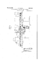
- Fig. 1 is a fragmentary side elevational view with parts in section illustrating somewhat diagrammatically a conventional two-table glassware forming machine embodying the present invention.
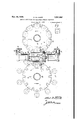
- Fig. 2 is. a sectional plan view taken substantially along the line IIII of Fig. 1.
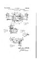
- v Fig. 3 is a fragmentary plan view of the driving mechanism and portions of the two mold tables.
- Fig. 4 is a sectional elevational view taken substantially along the line IVIV of Fig. 3.
- Fig.- 5 is an end elevational view of one of the fluid motors showing in dotted lines, the one-way check valve in the air supply line.
- Fig. 6 is a fragmentary sectional view through I by a piston rod 22 having' a piston 23 at each one of the fluid motors showing the cushioning device embodied therein.
- the present invention is illustrated in conjunction with a conventional two-table glassware forming machine of the type ordinarily 5 employed in the manufacture of milk bottles, this machine including a base ill, a pair of vertical stationary columns ll upon which blank and finishing mold tables l2 and I3 respectively are mounted for rotation.
- An annular series of blank molds I4 is arranged upon the blank mold table l2 and an annular series of partible finish ing molds I 5 is carried by the finishing mold table l3.
- Ring gears l6 and I I are secured to the lower sides of the blank and finishing mold tables l2 and I3 respectively and have driving connection to each other through an' intermediate gear l8 or pinion.
- the tables are designed for intermittent or step-by-step rotation about their vertical axes so that the molds are brought in succession to a series of stations providing for charging of the molds and a cycle of operations by means of which measured quantities of molten glass are transformed into finished articles and at the proper time discharged from the finishing molds.
- the driving mechanism which constitutes the present invention includes a pair of disks l9 or circular horizontally disposed plates suitably connected to the lower side of the ring. Gears I6 and I1 whereby they may rotate as a unit. Each disk is provided with an annular series of notches 20 or recesses which open through the periphery thereof. The walls of these notches may be tapered upwardly as shown or otherwise suitably shaped. Arranged between the two tables and below the intermediate gear It or pinion is mechanism for operatively engaging the disks I 9 in alternation and imparting stepby-step movement thereto. 40
- This mechanism includes a pair of opposed fluid operated motors 2
- a double rocker arm 25 Secured to the piston rod 22 is a double rocker arm 25 carrying at 'its opposite ends, tapered rollers 26 which are designed for engagement with the recesses in the disks l9.
- these rollers are adapted for engagement one at a time with the disks ii).
- the double rocker arm is slidingly supported upon a pair of'horizontal guide rods 21 extending parallel with the 55 piston rod 22 and constituting part of a frame disposed between the motors and two mold tables.
- Cross members 28 are suitably connected to the opposite ends of the guide rods 21 and formed with bearings 29 or guides for the piston rod 22.
- This frame, to which the double rocker arm is slidingly connected is intended to be rocked about the axis of the piston rod 22 at regular time intervals in order to effect operative engagement between the motors and mold tables in alterna- .tion.
- Rocking of the frame and therefore the double rocker arm 25 is obtained by means of a vertical piston motor 30 disposed below the frame and at one end thereof, said motor being connected to the latter by means of a piston rod 3
- the motor 30 may be air operated and obviously is timed to rock the frame and double rocker arm 25 in synchronism with operation of the two motors 2
- the rocking of the double arm 25 by the motor 30 causes the piston rod 22 and the pistons 23 connected thereto to be rocked within the cylinders 24.
- Any well known timer of which many have been developed for controlling bottle machine operations, may be employed in synchronizing operation of the several mechanisms herein shown.
- a cushioning device is built into the outer end of each motor 2
- the cushioning effect may be varied at will.
- Air under pressure is supplied to each of the motors by way of a supply pipe 36 and a check valve 3! which closes automatically immediately upon discontinuing the flow of air under pressure through the pipe 36.
- Fig. 1 the parts are illustrated at the termination of an indexing operation and the tapered roller 26 at the right end of the double rocker arm, is about to be disengaged from the disk on the blank mold table. This is accomplished, as stated heretofore, by operation of the motor 30, which operation simultaneously effects engagement between the other tapered roller and the disk carried by the finishing mold table [3. Immediately thereafter, the motor 2
- a pair of mold tables arranged side byside for rotation about separate vertical axes
- means for imparting rotary motion to the tables including a pair of fluid operated piston motors, table engaging mechanism arranged between the piston motors am actuated by operation of the latter -one at a time, and means forming a part of said mechanism and operable to effect engagement between said mechanism and the tables in alternation.
- a pair of mold tables ar-- ranged side by side for rotation about separate vertical axes, gears providing driving connection between said tables, means for imparting stepby-step rotation to said tables including a pair of fluid operated piston motors arranged at opposite sides of a center line extending through the axes of said tables, a piston rod connecting the two motors, table engaging mechanism carried by said piston rod, and. means for effecting operating connection between the mechanism and the tables in alternation.
- a pair of mold tables arranged side by side for rotation about separate vertical axes, gears providing driving connection between the tables, means for imparting step-bystep rotation to the tables including a pair of fluid operated piston motors arranged at opposite sides of a center line extending through the axes of said tables, a piston rod connecting the two motors, table engaging mechanism carried by said piston rod, means for effecting operative engagement between the mechanism and tables one at a time and means whereby each of the motors operates alternately to move the tables and as a cushioning device.
- a pair of opposed axially aligned horizontal piston motors a piston rod connecting the motors,' a frame mounted for rocking movement about, the axis of the piston rod, means for rocking said frame at regular time intervals, a double rocker arm attached to the piston rod for movement therewith in the direction of the length of said frame, rollers at the opposite ends of the rocker arm, means whereby rocking of said frame correspondingly moves the arm,andmeans whereby each motor alternately functions to move the rocker arm and as a cushioning device for the other motor.
- a pair of mold tables arranged side by side for rotation about separate vertical axes, gears providing driving connection between the tables, a disk carried by each table and arranged below the corresponding gear, each said disk having an annular series of recesses therein, a pair of fluid operated piston motors, a piston rod connecting the motors, rollers carried by thepiston rod, means for causing operative engagement of the rollers with the recessed disks one at a time, and means whereby each motor operates alternately to move the piston rod in one direction and as a cushioning device for the other motor.
- aoamea piston rod connecting the motors, a frame mounted for rocking movement upon and about the axis of the piston rod, a double rocker arm carried by the piston rod, rollers at the opposite ends of the rocker arm and means for rocking the frame and arm to thereby effect operative engagement between the rollers and recesses one at a time.
- a pair of mold tables ar ranged side by side for rotation about separate vertical axes, gears providing driving connection between the tables, a disk carried by each table and arranged below the corresponding gear, each said disk having an annular series. of recesses therein, a pair of fluid operated piston motors, a piston rod connecting the motors, a frame mounted for rocking movement on the pistonrod, a double rocker arm carried by the piston rod, rollers at the opposite ends of the rocker arm, and means for rocking the frame and arm to thereby 20 effect operative engagement between the rollers and recesses one at a time, each motor including an exhaust valve adjustable to regulate the rate of exhaust whereby the motors operate as cushioning devices as well as means to impart movement to the tables.
- Driving mechanism of the character described comprising a pair of opposed iaxially aligned piston motors, pistons therein, a piston rod connecting the pistons, means whereby each motor operates alternately to move the pistons and piston rod in one direction and cushion operation thereof in the other direction, means at least in part carried by the piston rod for effecting operative connection between said rod and a movable element at regular time intervals, said means carried by the piston rod including a frame mounted for rocking movement about the axis of the rod, a double rocker arm carried by the rod and at least in part slidingly supported on the frame and means for rocking the frame.
Description
Nov. 24, 1936. A. G. LAUCK 2,061,663
DRIVING MECHANISM FOR GLASSWARE FORMING MACHINES Filed July 13, 1955 5 Sheets-Sheet 1 A. G. LAUCK Nov. 24, 1936.
DRIVING MECHANISM FOR GLASSWARE FORMING MACHINES 5 Sheets-Sheet 2 Filed Jql y 15, 1955 A TTORNEY Patented Nov. 24, 1936 PATENT OFFICE DRIVING MECHANISM FOR GLASSWARE FORMING MACHINES Albert G. Lauck, Alton, Ill., assignor to Owens- Illinols Glass Company, a corporation of Ohio Application July 13,1935, Serial No. 31,218
9 Claims.
The present invention relates to improvements in driving mechanism for glassware forming machines and more particularly to means for driving machines of the type including blank and finishing mold tables arranged side by side and adapted for rotation in a step-by-step fashion.
Ordinarily glassware forming machines of the above type are driven by means of a single fluid motor of the horizontal piston type, driving connection between the motor and tables being obtained by means of rack and pinion mechanism. This rack and pinion mechanism is so actuated that the tables are indexed or moved in a step-by-step fashion by operation of the motor in one direction only, the reversal of the motor being an idle operation. Cushioning means in the form of a cylinder and piston therein suitably connected to the rack bar, reduces the shock and functions as a safety medium as is well known.
The present invention has for an object, the provision of a novel driving mechanism through the employment of which higher production speeds and higher operating efliciency can be obtained.
Another object is the provision of dual fluid operated piston motors connected together by means including devices for operatively engag ing the mold tables in alternation, each motor functioning while operating'in one direction to index the tables andin the other direction as a cushioning cylinder.
A further object is the provision of novel means for operatively connecting the fluid motors and mold tables.
Other objects will be in part apparent and in part pointed out hereinafter.
In the drawings:
Fig. 1 is a fragmentary side elevational view with parts in section illustrating somewhat diagrammatically a conventional two-table glassware forming machine embodying the present invention.
Fig. 2 is. a sectional plan view taken substantially along the line IIII of Fig. 1.
v Fig. 3 is a fragmentary plan view of the driving mechanism and portions of the two mold tables.
Fig. 4 is a sectional elevational view taken substantially along the line IVIV of Fig. 3.
Fig.- 5 is an end elevational view of one of the fluid motors showing in dotted lines, the one-way check valve in the air supply line.
' Fig. 6 is a fragmentary sectional view through I by a piston rod 22 having' a piston 23 at each one of the fluid motors showing the cushioning device embodied therein.
The present invention is illustrated in conjunction with a conventional two-table glassware forming machine of the type ordinarily 5 employed in the manufacture of milk bottles, this machine including a base ill, a pair of vertical stationary columns ll upon which blank and finishing mold tables l2 and I3 respectively are mounted for rotation. An annular series of blank molds I4 is arranged upon the blank mold table l2 and an annular series of partible finish ing molds I 5 is carried by the finishing mold table l3. Ring gears l6 and I I are secured to the lower sides of the blank and finishing mold tables l2 and I3 respectively and have driving connection to each other through an' intermediate gear l8 or pinion. The tables are designed for intermittent or step-by-step rotation about their vertical axes so that the molds are brought in succession to a series of stations providing for charging of the molds and a cycle of operations by means of which measured quantities of molten glass are transformed into finished articles and at the proper time discharged from the finishing molds.
The driving mechanism which constitutes the present invention includes a pair of disks l9 or circular horizontally disposed plates suitably connected to the lower side of the ring. gears I6 and I1 whereby they may rotate as a unit. Each disk is provided with an annular series of notches 20 or recesses which open through the periphery thereof. The walls of these notches may be tapered upwardly as shown or otherwise suitably shaped. Arranged between the two tables and below the intermediate gear It or pinion is mechanism for operatively engaging the disks I 9 in alternation and imparting stepby-step movement thereto. 40
\This mechanism includes a pair of opposed fluid operated motors 2| arranged'at opposite sides of a center line extending through the axes of the tables, the motors being connected together end disposed within the corresponding motor cylinder 24. Secured to the piston rod 22 is a double rocker arm 25 carrying at 'its opposite ends, tapered rollers 26 which are designed for engagement with the recesses in the disks l9.
As indicated above, these rollers are adapted for engagement one at a time with the disks ii). To effect such engagement, the double rocker arm is slidingly supported upon a pair of'horizontal guide rods 21 extending parallel with the 55 piston rod 22 and constituting part of a frame disposed between the motors and two mold tables. Cross members 28 are suitably connected to the opposite ends of the guide rods 21 and formed with bearings 29 or guides for the piston rod 22. This frame, to which the double rocker arm is slidingly connected, is intended to be rocked about the axis of the piston rod 22 at regular time intervals in order to effect operative engagement between the motors and mold tables in alterna- .tion.
Rocking of the frame and therefore the double rocker arm 25 is obtained by means of a vertical piston motor 30 disposed below the frame and at one end thereof, said motor being connected to the latter by means of a piston rod 3| having a fork 32 at its outer end in which a pair of grooved rollers 33 are mounted. These rollers (Figs. 1 and 4) engage opposite sides of one of the guide rods 21 and thereby operatively connect the frame and motor 30. The motor 30 may be air operated and obviously is timed to rock the frame and double rocker arm 25 in synchronism with operation of the two motors 2|. The rocking of the double arm 25 by the motor 30 causes the piston rod 22 and the pistons 23 connected thereto to be rocked within the cylinders 24. Any well known timer, of which many have been developed for controlling bottle machine operations, may be employed in synchronizing operation of the several mechanisms herein shown.
A cushioning device is built into the outer end of each motor 2|, the construction including a series of graduated ports 34 in the exhaust line 35 by means of which the rate of exhaust of air under pressure from the motor cylinders may be regulably controlled. Thus, the cushioning effect may be varied at will. For details concerning this feature, reference may be had to Soubier Patent #1371 .742 dated October 23, 1934. Air under pressure is supplied to each of the motors by way of a supply pipe 36 and a check valve 3! which closes automatically immediately upon discontinuing the flow of air under pressure through the pipe 36.
In view of the above, it is apparent that operation of the mechanism involves application of air under pressure to the motors one at a time so that each may operate alternately as a driving medium and a cushioning device. In Fig. 1 the parts are illustrated at the termination of an indexing operation and the tapered roller 26 at the right end of the double rocker arm, is about to be disengaged from the disk on the blank mold table. This is accomplished, as stated heretofore, by operation of the motor 30, which operation simultaneously effects engagement between the other tapered roller and the disk carried by the finishing mold table [3. Immediately thereafter, the motor 2| at the lower side of Fig. 2 will operate to index the tables, the other motor functioning as a cushioning device as is apparent.
Modifications may be resorted to within the spirit and scope of the appended claims.
I claim:
1. In combination, a pair of mold tables arranged side byside for rotation about separate vertical axes, means for imparting rotary motion to the tables including a pair of fluid operated piston motors, table engaging mechanism arranged between the piston motors am actuated by operation of the latter -one at a time, and means forming a part of said mechanism and operable to effect engagement between said mechanism and the tables in alternation.
2. In combination, a pair of mold tables ar-- ranged side by side for rotation about separate vertical axes, gears providing driving connection between said tables, means for imparting stepby-step rotation to said tables including a pair of fluid operated piston motors arranged at opposite sides of a center line extending through the axes of said tables, a piston rod connecting the two motors, table engaging mechanism carried by said piston rod, and. means for effecting operating connection between the mechanism and the tables in alternation.
3. In combination, a pair of mold tables arranged side by side for rotation about separate vertical axes, gears providing driving connection between the tables, means for imparting step-bystep rotation to the tables including a pair of fluid operated piston motors arranged at opposite sides of a center line extending through the axes of said tables, a piston rod connecting the two motors, table engaging mechanism carried by said piston rod, means for effecting operative engagement between the mechanism and tables one at a time and means whereby each of the motors operates alternately to move the tables and as a cushioning device.
4. In driving mechanism of the character described, a pair of opposed axially aligned horizontal. piston motors, a piston rod connecting the motors, a frame mounted for rocking movement upon the piston rod, means for rocking said frame at regular time intervals, a double rocker arm attached to the piston rod for movement therewith in the direction of the length of said frame, rollers at the opposite ends of the rocker arm to engage a movable element and means whereby rocking of said frame correspondingly moves the arm.
5. In driving mechanism of the character described, a pair of opposed axially aligned horizontal piston motors, a piston rod connecting the motors,' a frame mounted for rocking movement about, the axis of the piston rod, means for rocking said frame at regular time intervals, a double rocker arm attached to the piston rod for movement therewith in the direction of the length of said frame, rollers at the opposite ends of the rocker arm, means whereby rocking of said frame correspondingly moves the arm,andmeans whereby each motor alternately functions to move the rocker arm and as a cushioning device for the other motor.
6. In combination, a pair of mold tables arranged side by side for rotation about separate vertical axes, gears providing driving connection between the tables, a disk carried by each table and arranged below the corresponding gear, each said disk having an annular series of recesses therein, a pair of fluid operated piston motors, a piston rod connecting the motors, rollers carried by thepiston rod, means for causing operative engagement of the rollers with the recessed disks one at a time, and means whereby each motor operates alternately to move the piston rod in one direction and as a cushioning device for the other motor.
7. In combination, a pair of mold tables arranged side by side for rotation about separate vertical axes, gears providing driving connection between the tables, a disk carried by each table and arranged below the corresponding gear, each said disk having an annular series of recesses therein, a pair of fluid operated piston motors, a.
aoamea piston rod connecting the motors, a frame mounted for rocking movement upon and about the axis of the piston rod, a double rocker arm carried by the piston rod, rollers at the opposite ends of the rocker arm and means for rocking the frame and arm to thereby effect operative engagement between the rollers and recesses one at a time.
8. In combination, a pair of mold tables ar ranged side by side for rotation about separate vertical axes, gears providing driving connection between the tables, a disk carried by each table and arranged below the corresponding gear, each said disk having an annular series. of recesses therein, a pair of fluid operated piston motors, a piston rod connecting the motors, a frame mounted for rocking movement on the pistonrod, a double rocker arm carried by the piston rod, rollers at the opposite ends of the rocker arm, and means for rocking the frame and arm to thereby 20 effect operative engagement between the rollers and recesses one at a time, each motor including an exhaust valve adjustable to regulate the rate of exhaust whereby the motors operate as cushioning devices as well as means to impart movement to the tables.
9. Driving mechanism of the character described, comprising a pair of opposed iaxially aligned piston motors, pistons therein, a piston rod connecting the pistons, means whereby each motor operates alternately to move the pistons and piston rod in one direction and cushion operation thereof in the other direction, means at least in part carried by the piston rod for effecting operative connection between said rod and a movable element at regular time intervals, said means carried by the piston rod including a frame mounted for rocking movement about the axis of the rod, a double rocker arm carried by the rod and at least in part slidingly supported on the frame and means for rocking the frame.
ALBERT G. LAUCK.
Priority Applications (1)
| Application Number | Priority Date | Filing Date | Title |
|---|---|---|---|
| US31218A US2061663A (en) | 1935-07-13 | 1935-07-13 | Driving mechanism for glassware forming machines |
Applications Claiming Priority (1)
| Application Number | Priority Date | Filing Date | Title |
|---|---|---|---|
| US31218A US2061663A (en) | 1935-07-13 | 1935-07-13 | Driving mechanism for glassware forming machines |
Publications (1)
| Publication Number | Publication Date |
|---|---|
| US2061663A true US2061663A (en) | 1936-11-24 |
Family
ID=21858232
Family Applications (1)
| Application Number | Title | Priority Date | Filing Date |
|---|---|---|---|
| US31218A Expired - Lifetime US2061663A (en) | 1935-07-13 | 1935-07-13 | Driving mechanism for glassware forming machines |
Country Status (1)
| Country | Link |
|---|---|
| US (1) | US2061663A (en) |
Cited By (2)
| Publication number | Priority date | Publication date | Assignee | Title |
|---|---|---|---|---|
| US3147105A (en) * | 1957-07-25 | 1964-09-01 | Owens Illinois Glass Co | Apparatus for molding glass |
| US3495965A (en) * | 1967-08-07 | 1970-02-17 | Armstrong Cork Co | Mechanical cushion for piston type glass pressing apparatus |
-
1935
- 1935-07-13 US US31218A patent/US2061663A/en not_active Expired - Lifetime
Cited By (2)
| Publication number | Priority date | Publication date | Assignee | Title |
|---|---|---|---|---|
| US3147105A (en) * | 1957-07-25 | 1964-09-01 | Owens Illinois Glass Co | Apparatus for molding glass |
| US3495965A (en) * | 1967-08-07 | 1970-02-17 | Armstrong Cork Co | Mechanical cushion for piston type glass pressing apparatus |
Similar Documents
| Publication | Publication Date | Title |
|---|---|---|
| US3445218A (en) | Parison transfer and invert mechanism | |
| US1974837A (en) | Bottle transferring apparatus | |
| US2061663A (en) | Driving mechanism for glassware forming machines | |
| US3630709A (en) | Blowhead-operating mechanism | |
| US2183223A (en) | Stenciling apparatus | |
| US3198617A (en) | Mechanism for pressing charges of molten glass in a forming mold | |
| WO1984003501A1 (en) | Improved blank cylinder apparatus | |
| US1745794A (en) | Glass-fabricating machine | |
| US2832235A (en) | Hydraulic valve control for intermittent driving mechanism | |
| US2384498A (en) | Glass forming machine | |
| US2565749A (en) | Drive for hollow glassware forming apparatus | |
| US1895824A (en) | Transfer apparatus for glassware | |
| US3241941A (en) | Neck mold apparatus for glass forming machine | |
| US3240582A (en) | Method for forming and delivering glass | |
| US1959428A (en) | Glassware forming machine | |
| US2634552A (en) | Take-out device for glass blowing machines | |
| US2783591A (en) | Glass making machine with dual cylinder press plungers | |
| US2244809A (en) | Tumbler press | |
| US1949886A (en) | Glassware forming machine | |
| US3069860A (en) | Glass forming machine | |
| US1401713A (en) | Automatic machine for blowing glass | |
| US2225631A (en) | Hydraulic machine for molding glass articles | |
| US2142006A (en) | Timing system for glass feeders | |
| US2365929A (en) | Machine for blowing hollow glassware | |
| US3303013A (en) | Takeout apparatus for glass forming machines |