US2061277A - Key controlled apparatus - Google Patents
Key controlled apparatus Download PDFInfo
- Publication number
- US2061277A US2061277A US317894A US31789428A US2061277A US 2061277 A US2061277 A US 2061277A US 317894 A US317894 A US 317894A US 31789428 A US31789428 A US 31789428A US 2061277 A US2061277 A US 2061277A
- Authority
- US
- United States
- Prior art keywords
- selecting
- column
- perforating
- relays
- representing
- Prior art date
- Legal status (The legal status is an assumption and is not a legal conclusion. Google has not performed a legal analysis and makes no representation as to the accuracy of the status listed.)
- Expired - Lifetime
Links
Images


Classifications
-
- G—PHYSICS
- G06—COMPUTING OR CALCULATING; COUNTING
- G06K—GRAPHICAL DATA READING; PRESENTATION OF DATA; RECORD CARRIERS; HANDLING RECORD CARRIERS
- G06K13/00—Conveying record carriers from one station to another, e.g. from stack to punching mechanism
- G06K13/02—Conveying record carriers from one station to another, e.g. from stack to punching mechanism the record carrier having longitudinal dimension comparable with transverse dimension, e.g. punched card
- G06K13/08—Feeding or discharging cards
Definitions
- This invention relates to a key controlled apparatus, and more particularly to an electricallycontrolled keyboard for selectively conveying in- 4 formation to a statistical card perforating ap-
- the primary object of the present invention is the provision of a simplified key controlled apparatus having a number of keys representing characters, each of which may be depressed, to
- One embodiment of the invention comprises a keyboard of nine keys representing the digits-l, 2,
- the keys are electrically connected to individual brushes of a switching mechanism, and each brush is associated with an arcuate bank of forty -flve stationary contact terminals and mounted on a common shaft which is rotated one step at a time to cause the brushes to contact successively with each of the forty-five contact terminals.
- Each position of the brushes corresponds to a column in a predetermined location on a statistical record card and connects the keys to a group of digital lockmg relays which control the indication of the diglts in a column.
- Each relay of the group is arranged, when operated, to eflect a perforation in a correspondingly positioned column of a statistical record card.
- the depression of one of the keys in the unitary keyboard operates and locks the corresponding relay in the group to which it is connected and effects rotation of the common brush shaft one step, thereby disconnecting the keyboard from one group of relays and connecting it to the group or column of next highest order.
- a space key is also provided for rotating thebrush shaft one step at a time without operating a digital key when it is desired that none of the digits be indicated in a particular column.
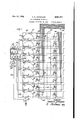
- Figs. 1 and 2 are circuit diagrams of one embodiment of the invention, which, when viewed collectively with Fig. 2 to the right of Fig. 1,.
- d sclose a unitary electrical keyboard inconjunction with a card perforating mechanism
- Fig. 3 is a fragmentary plan view of a perforat ing apparatus equipped with the electrical keyboard;
- Fig. 4 is a front elevational view of the electroinstant.
- the frame also has fastened thereto a magnetically operated switching mechanism, and
- Fig. 5 is a plan view thereof.
- a keyboard 55 which is shown in Figs. 1 and 3, nine depressible keys 56 representing the digits l, 2. 3, 4, 5, 6, '7, 8 and 9, re- 5 spectively, are electrically connected to individual brushes-of a switching mechanism designated generally by the numeral 51.
- the switching mechanism 51 consists of nine arcuate banks 6
- An elongated spring contact 09 is provided in each of the arcuate banks 60 15 for contacting continuously with a circular portion 8U ofthe associated brush to connect it to ground- Rotation of the brushes is effected through a ratchet wheel 15 (Figs. 4 and 5) which is secured to a shaft 16 upon which the brushes 20 are insulatlvely mounted.
- the shaft 16 is journaled in a frame i1 and carries a dial 18 for in- 'dicating-rotative positions 1 to 45 inclusive, for
- a pointer 14 secured to the frame 1'! and associated with the dial i8 is adapted to'indicate the rotative position of the nine brush-.sat any spring holding pawl I9 and an electromagnet 8t 0 for actuating a ratchet spring 8! attached to an arm 82 of an armature 83.
- the armature 83 of the electromagnet is pivoted on a depending lug 84 of the frame 17 and has an arm 85 at- 35 tached to a coil spring 88 having its other end secured to the frame Tl.
- a space key 81 is provided on the keyboard SI for eflecting rotation of the brushes 3-1! one step at a time without operat- 55 ing a digital key when a zero is to'be indicated in a particular column or columns.
- the forty-five stationary contacts SI of the arcuate banks 60 associated with the digital 5 brushes 63-II represent forty-five corresponding- --ly positioned columns in a record card and consequently are electrically connected to forty-five groups dr'columns of digital locking relays 9!.
- indicating correspondin 10 1y positioned columns of the digits in a record card are in turn electrically connected to a perforating apparatus designated generally by'the numeral 95.
- in a group is connected; by a conductor to correspondingly numbered terminals in arcuate banks 90 of individual selecting switches 91 commonly used in telephonic communicating systems. It will benoted. that none of the relays has been provided for ciphers,
- the relay will remain energized until the locking circuit is broken by the operation of a clear-cut switch l3l.
- each brush or switch arm I03 of the plurality of selecting switches 95 is secured to a rotatable shaft I04 which is keyed to a pinion I05 meshing with a rack I06.
- This rack meshes with a spur gear I01 .65 secured to a shaft I08 which drives a segmental gear I09.
- the segmental gear at difierent points in its rotation, is adapted to engage and drive .at predetermined intervals a pluralityof selecting bars I I0 representing columns in a record card 70 and having enlarged end portions I I I of suflicient size iorengaging one at a time aplurality of per forating pins I I 2 arranged in rowsor columns, each perforating pin in a column representing one of the numbers 0, l, 2, 3, 4, 5, 6, '7, 8, and 9, respec- 75 tively.
- The-engagement of each selecting bar I I0 with the segmental gear I09 is controlled by an individual bell crank lever Ii3 pivoted on a rod III and held in a normal position by a spring I I5.
- An arm IIB of the bell crank lever I I3 engages an armature II! of a selecting electromagnet 0 so 5 that when the selecting electromagnet is energized the armature will swing the bell crank lever clockwise and elevate the particular selecting bar into engagement with-the rotating segmental gear I09;
- the selecting bars IIO which 10 are selected at different points in the rotation of the segmental gear through the operation of the a selecting electromagnets II8 are advanced to positions with their enlarged end portions III in 7 vertical alignment with the desired g oratingm pins. At this point in the operation a record card has been properly positioned directly beneath the perforating pins.
- the mechanism for actuating the ram I22 30 and oscillating the segmental gear I09 first in a clockwise direction to advance the selector bars IIO into association with the perforating pins and then in a counter-clockwise direction to retract the selector bars to their'normal position 3 comprises a cam wheel 20I mountedon a shaft .202 which is adaptedto be rotated through one revolution upon the manual actuation of a switch bar 203 positioned on the keyboard 55.
- the switch bar 203 may be actuated manually after 0 the information to be periorated in a card .has been set up by'nieans of thekeys 56 and the space bar 81.
- the switch bar 203 upon being so actuated, connects grounded battery at 200 through a contact 205 to the winding of an elec- 45 tromagnetic clutch 208 and then back to ground at 201.
- the electromagnetic clutch 200 may be of any suitable known type which, upon actuation, causes the engagement of a driving element with a' driven element for one revolution and 50 thereupon automatically disconnects them.
- the clutch 206 connects the shaft 202 to'a continually rotating shaft 208 driven by amotor 209 to cause the-cam wheel 20I to move through one complete revolution in the 55 direction indicatedby the arrow in Fig. 2.
- Alink 2" is securedat one end to the ram I22 and at its other-end is provided with a cam roller which cooperates with a groove H3 in the cam wheel 20l to impart a reciprocatory motion 60 -to the ram upon rotation of the cam wheel.
- extension of the rack I06 also carries a camroller 2 which rides in a second cam groove 2I5 formed in the cam wheel 20I and a reciprocatory motion is imparted to the rack upon rotation of the cam wheel.
- the reciprocation of the rack I06 and the link 2 and the consequent oscillation'of the segmental gear I09 and reciprocation of the ram I22 are so timed by the formation of the cam grooves that the sequence of operation thereof will be as follows:
- the segmental gear I09 will be rotated in a clockwise direction to advance-the selected selector bars II0, the ram I22 will be moved downwardly to drive the selected 4 perforating pins II2 through the card and up- "15 counter-clockwise direction to retract the adva'noed selector bars.
- Electromagnet Blis thus energized and in a manner previously described advances the brushes 25 63- from the contacts 2 to the contacts 3.
- a circuit from ground is established through the right hand contacts of the relays 9
- in the desired-columns have thus been operated by the keys 56 and as has been previously described to thereby electrically control the selection of theproper perforating pins 2 in the perforating apparatus by connecting groundto their associated contacts 96 so that when the brushes I03 engage the contacts which are connected to ground the selecting electromagnets associated therewith will be momentarily energized.
- the operator connects the shaft I08 of the perforating apparatus 95 to a suitable driving means as shown and described in detail in the copending application of H. G. Johnstone et al., Serial No. 302,463, filed August 28, 1928, as shown schematically in Fig. 2 and described hereinbefore' Upon rotation of the shaft. I08, the segmental gear I09 and the spur gear I01 are rotated; the
- a cir- 75 cult is completed to energize the particular select ing electromagnet H8 and operate its associated bell crank lever H3 to bring the-selecting bar H representing the particular column into engagement with the rotating segmental gear I09 and thus advance the selecting bar I'M :a distance commensurate with the time of its initial actuation.
- the selector bar H0 upon being moved into engagement with the segmental gear and being-moved to the left (Fig.
- the time of actuation of the selecting bars 0 in a clockwise rotative cycle of the segmental gear is dependent on the numerical valued the digit to be recorded; that is, the selecting bar to cause the recording of a digit 9 is actuated at the her ginning of the rotative cycle, a selecting bar to record adigit 4 is'actuated five periods of. time later, and aselecting bar to record a'zero-nine periods of time later.
- the selecting bar I l 0 representing the first column will be actuated at the start of the rotative cycle of the seg-.
- the brush I03 representing the first column effects the energization and operatlonof the associated selecting electromagnet 8 through the following circuit:
- the brush 10 From grounded battery 0 through the winding 1 of the electromagnet 8 representing the first column, the brush 10: time selecting switch 91 representing the first column, terminal 9 in the associated arcuate bank 98', conductor Ill, conductor I29, left hand contact of the digit .9 locking relay in the-first column 98 to ground.
- the operation of'the selecting electromagnet lldrepresenting the first column elevates the correspondingselecting bar H0 into engagement with the segmental gear and the selecting bar is advanced to select the digit 9 perforating pin "2 as previously explained.
- the operation of the electromagnet 8 for the fourth column causes the associated selecting bar ll-llj b actuated and advanced to select a perforating pin representing the digit 4 in the fourth column.
- clear-out switch BI is moved to the right to open the energizing circuit to the digital locking relays 9
- the clear-out switch l3l is then moved to the leftand the electrical keyboard and perforating apparatus is put,-in condition to receive and record other information in any of the forty-five columns selected.
- perforating means thereafter controlled by said electromagnetic means comprising a plurality of electromagnets associated with all of the 'electromagnetic means, a plurality of perforators',
- a key for each of a plurality of characters, a registering m controlled by thekeys comprising a plurality of groups of relays, .a plurality of electromagnets each electromagnet. associated with a group of" relays and operable at a predetermined moment depending upon. which relay in its associated group has been operated, a plurality of per- .forators, means responsiveto the actuated relays for controllingthe operation 'of theelectromagnets to select a .perforator forv actuation, andmeans for actuating the perforators selected.
- a perforating including a 'plurality of'groups of perforators, a 7;
- keyboard comprising keys representing characters, relays representative of the characters and associated with the perforators, means for successively associating the'keys with said relays representative of the-characters, means operative thereafter for causing the representative relays to control electrically the selection of perforators in accordance with the operation of the keyboard, and means for actuating the, selected perforators.
- a perforator selector as-" sociated with each group of perforators, control means for each perforator selector, and means for determining the time of actuation of the control means thereby to determine the perforator v selected comprising a keyboard having keys representing characters, a plurality of groups of registering means, means for associating the keyboard successively with each group of registering means, and means thereafter operated for selectively operating the control means.
- a perforator selector associated with each column, means for actuating selected perforators, means for advancing a perforator selector into position to select a. perforator for'actuation, and means for electrically controlling the selection of the perforators including a keyboard, a plurality of groups of registering relays, and means for successively associating the keyboard with each group of registering relays.
- a key for each of a plurality of char acters a plurality of groups of digital locking .actuation of a key.
- a mechanism for recording information in a record a plurality of keys equal in number to the numberv of characters used, each of the keys representing a different character, locking relays controlled by the keys for storing all of the information before recording, a plurality of recording elementsfor. each character and positioned in predetermined areas, and means electrically controlled by the locking relays for subsequently selecting from a plurality of the recording elements those elements necessary to effect the recording in predetermined areas in accordance with the information stored.
- a mechanism for permanently recording information in a record a plurality of keys equal in number to the number of characters used, each of the keys representing a .,difierent character, locking electromagnetic devices cont-rolled by the keys for storing all of the information before recording, a plurality of permanently recording elements foreach characterand positioned in predetermined areas, means controlled by the electromagnetic locking devices for subsequently selecting from a plurality of the recording elements those elements necessary to efiect the recording in predetermined areas in accordance with the information stored and means for simultaneously actuating all of the selected recording elements in a single recording operation.
- a perforating mechanism including a plurality of groups of perforators, .a keyboard comprising keys representing characters, each key representing a different character, a plurality of electromagnetic devices representative of each of the characters and associated with the perforators, means for successively associating the keys with said electromagnetic devices, means operative thereafter for causing the electromagnetic devices to control the selection ofperforators in accordance with the operation of the keyboard, and means for actuating the selected perforators.
- a card perforating mechanism a plurality of perforators arranged in columns, a plurality of perforator selectors, one associated with each column, means for actuating selected perforators, means for advancing a perforator selectorinto position to select a perforator for actuation, andmeans for controlling the selection of the perforators including a keyboard, a plurality of groups of registering electromagnetic devices, and means for successively associating the keyboard with each group of registering electromagnetic devices.
- a plurality of sets of permanently recording members electrically controlled selecting means individual to each set of recording members to determine the recording member to be actuated in that set, means individual to and electrically connected to each selecting means for storing digits to be recorded, and a contact making means representing a single set of all of the digits and electrically connected to and common to all of the storing means for selectively determining which of the storing means 6 I w recordink members representing charactero, a
- electrical mandrel-selectively predetermined elements tor oneratimfm NP resentative or characters and'eommon to all of said electrlmlmeans for determhqns therapeuwarm? 7 tion of said electrical means, and means for opcrating the conditioned elements to efiect the seelection and operation-o1 the desired recording members to record the selected characters in predetexmined'positions in a record sheet.
Landscapes
- Physics & Mathematics (AREA)
- General Physics & Mathematics (AREA)
- Engineering & Computer Science (AREA)
- Theoretical Computer Science (AREA)
- Lock And Its Accessories (AREA)
Description
Nov. 17, 1936. H. e. JOHNSTONE I 3 L KEY CONTROLLED APPARATUS Original Filed Nov. 8, l928 3 Sheets-Sheet 1 Nov. 17, 1936. H. G. JOHNSTONE KEY CONTROLLED APPARATUS 3 Sheets-Sheet 3 Original Filed Nov.- 8, 1928 fd/d d da/wsfa/re Patented Nov. 17, 1936 '1 UNITED STATES PATENT OFFIC KEY CONTROLLED ArrAnA'rUs Application November 8. iota-sum No. 317,894 Renewed June 9, 1932 is Claims. (oi. 164-113) This invention relates to a key controlled apparatus, and more particularly to an electricallycontrolled keyboard for selectively conveying in- 4 formation to a statistical card perforating ap- The primary object of the present invention is the provision of a simplified key controlled apparatus having a number of keys representing characters, each of which may be depressed, to
selectively indicate that character in any one of a number of predetermined positions. I
One embodiment of the invention comprises a keyboard of nine keys representing the digits-l, 2,
3, 4, 5, 6, 7, 8 and 9, respectively. The keys are electrically connected to individual brushes of a switching mechanism, and each brush is associated with an arcuate bank of forty -flve stationary contact terminals and mounted on a common shaft which is rotated one step at a time to cause the brushes to contact successively with each of the forty-five contact terminals. Each position of the brushes corresponds to a column in a predetermined location on a statistical record card and connects the keys to a group of digital lockmg relays which control the indication of the diglts in a column. Each relay of the group is arranged, when operated, to eflect a perforation in a correspondingly positioned column of a statistical record card. The depression of one of the keys in the unitary keyboard operates and locks the corresponding relay in the group to which it is connected and effects rotation of the common brush shaft one step, thereby disconnecting the keyboard from one group of relays and connecting it to the group or column of next highest order. A space key is also provided for rotating thebrush shaft one step at a time without operating a digital key when it is desired that none of the digits be indicated in a particular column.
The above and other features of the present invention will be fully set forth in the following description and appended claims, and will be more readily understood by reference to the accompanying drawings, wherein Figs. 1 and 2 are circuit diagrams of one embodiment of the invention, which, when viewed collectively with Fig. 2 to the right of Fig. 1,.
d sclose a unitary electrical keyboard inconjunction with a card perforating mechanism;
Fig. 3 is a fragmentary plan view of a perforat ing apparatus equipped with the electrical keyboard; Fig. 4 is a front elevational view of the electroinstant. The frame also has fastened thereto a magnetically operated switching mechanism, and
Fig. 5 is a plan view thereof.
Referring now to a keyboard 55 which is shown in Figs. 1 and 3, nine depressible keys 56 representing the digits l, 2. 3, 4, 5, 6, '7, 8 and 9, re- 5 spectively, are electrically connected to individual brushes-of a switching mechanism designated generally by the numeral 51.
The switching mechanism 51 consists of nine arcuate banks 6|! of forty-five stationary con- 10 tacts 6| representing forty-five columns and nine rotatable-brushes 83-1! representing the digits 1-9, each brush being individual to a bank of forty-five contacts. An elongated spring contact 09 is provided in each of the arcuate banks 60 15 for contacting continuously with a circular portion 8U ofthe associated brush to connect it to ground- Rotation of the brushes is effected through a ratchet wheel 15 (Figs. 4 and 5) which is secured to a shaft 16 upon which the brushes 20 are insulatlvely mounted. The shaft 16 is journaled in a frame i1 and carries a dial 18 for in- 'dicating-rotative positions 1 to 45 inclusive, for
each half revolution of the ratchet wheel 15. The rotative positions correspond to the forty-five 25 contacts 6! representing the same number of columns. A pointer 14 secured to the frame 1'! and associated with the dial i8 is adapted to'indicate the rotative position of the nine brush-.sat any spring holding pawl I9 and an electromagnet 8t 0 for actuating a ratchet spring 8! attached to an arm 82 of an armature 83. The armature 83 of the electromagnet is pivoted on a depending lug 84 of the frame 17 and has an arm 85 at- 35 tached to a coil spring 88 having its other end secured to the frame Tl.
From the foregoing description it will be readily understood that upon energization of the electromagnet 80 by depressing one of the digital 40 keys 56, its armature 83 will be rocked counterclockwise against' the tension of the spring 86, to move the ratchet spring 8| back over one tooth in the ratchet wheel 15. Deenergizing the electromagnet by releasing the depressed digital key 45 permits the tension of the spring 86 to move the armature 83 and its ratchet spring 8i clockwise to rotate the ratchet wheel 15, shaft I6 and the accompanying nine brushes 63-1! through a distanceequal to one tooth on the ratchet wheel or 50 one mtative'position whereby the brushes are caused to engage the succeeding contacts in the arcuate banks 80. A space key 81 is provided on the keyboard SI for eflecting rotation of the brushes 3-1! one step at a time without operat- 55 ing a digital key when a zero is to'be indicated in a particular column or columns.
'The forty-five stationary contacts SI of the arcuate banks 60 associated with the digital 5 brushes 63-II represent forty-five corresponding- --ly positioned columns in a record card and consequently are electrically connected to forty-five groups dr'columns of digital locking relays 9!. The groups of relays 9| indicating correspondin 10 1y positioned columns of the digits in a record card are in turn electrically connected to a perforating apparatus designated generally by'the numeral 95. Each digital relay 9| in a group is connected; by a conductor to correspondingly numbered terminals in arcuate banks 90 of individual selecting switches 91 commonly used in telephonic communicating systems. It will benoted. that none of the relays has been provided for ciphers,
' -but that the right hand contacts of the digital relays in the columns are connected in series to establish circuits to the zero (0) terminals in the arcuate banks'96 of the selecting switches 9I.'
In case a digital key isdepressed in a column the circuit is opened, but if no digital key is depressed .then a cipher is'automatically indicated in the perforating apparatus for thatparticular column. A plurality of digits can be indicated in a column by depressing simultaneously a plurality of the digital keys 56 to establish circuits to energize and lock corresponding digital relays 9| in the column designated by the position of the brushes 63-Il. p
7 Upon energization of a digital lockingrelay 9I -due to the depression of itsasodated key 56,
- which is associated therewith through one of the -digital brushes 03- to II, the relay will remain energized until the locking circuit is broken by the operation of a clear-cut switch l3l.
In order to avoid an unnecessary duplication and complication of only two of the selecting switches 91 connected to the first and forty-fifth columns 98 and I00, respectively, of the locking relays are'illusiu'ated in the circuit schematically, but it will be understood that similar' selecting switches in the perforating appara tus 95 are provided for each of the other columns in the record card; To'further simplify the-circuit, only the first, twenty-second and forty- fifth columns 98, 99, and I00, respectively, of the digital relays are shown.- The positions of the second to the 'twenty-first columns, inclusive, and
- the twenty-third to the iorty-fom'th colmnns of relays 9| are indicated by the dotted rectangles IN and I02, respectively, and it is to be' understood that these columns or groups of relays are 0 connected in amanner similar to that shown for the first and forty-fifth columns, 98 and I00, to corresponding individual selecting switches 91 in the perforating apparatus 95.
'60 In the perforating apparatus, each brush or switch arm I03 of the plurality of selecting switches 95 is secured to a rotatable shaft I04 which is keyed to a pinion I05 meshing with a rack I06. This rack meshes with a spur gear I01 .65 secured to a shaft I08 which drives a segmental gear I09. The segmental gear; at difierent points in its rotation, is adapted to engage and drive .at predetermined intervals a pluralityof selecting bars I I0 representing columns in a record card 70 and having enlarged end portions I I I of suflicient size iorengaging one at a time aplurality of per forating pins I I 2 arranged in rowsor columns, each perforating pin in a column representing one of the numbers 0, l, 2, 3, 4, 5, 6, '7, 8, and 9, respec- 75 tively. The-engagement of each selecting bar I I0 with the segmental gear I09 is controlled by an individual bell crank lever Ii3 pivoted on a rod III and held in a normal position by a spring I I5. An arm IIB of the bell crank lever I I3 engages an armature II! of a selecting electromagnet 0 so 5 that when the selecting electromagnet is energized the armature will swing the bell crank lever clockwise and elevate the particular selecting bar into engagement with-the rotating segmental gear I09; The selecting bars IIO which 10 are selected at different points in the rotation of the segmental gear through the operation of the a selecting electromagnets II8 are advanced to positions with their enlarged end portions III in 7 vertical alignment with the desired g oratingm pins. At this point in the operation a record card has been properly positioned directly beneath the perforating pins.
tion. "The mechanism for actuating the ram I22 30 and oscillating the segmental gear I09 first in a clockwise direction to advance the selector bars IIO into association with the perforating pins and then in a counter-clockwise direction to retract the selector bars to their'normal position 3 comprises a cam wheel 20I mountedon a shaft .202 which is adaptedto be rotated through one revolution upon the manual actuation of a switch bar 203 positioned on the keyboard 55. The switch bar 203 may be actuated manually after 0 the information to be periorated in a card .has been set up by'nieans of thekeys 56 and the space bar 81. The switch bar 203; upon being so actuated, connects grounded battery at 200 through a contact 205 to the winding of an elec- 45 tromagnetic clutch 208 and then back to ground at 201. The electromagnetic clutch 200 may be of any suitable known type which, upon actuation, causes the engagement of a driving element with a' driven element for one revolution and 50 thereupon automatically disconnects them. In the embodiment shown, the clutch 206 connects the shaft 202 to'a continually rotating shaft 208 driven by amotor 209 to cause the-cam wheel 20I to move through one complete revolution in the 55 direction indicatedby the arrow in Fig. 2.
Alink 2" is securedat one end to the ram I22 and at its other-end is provided with a cam roller which cooperates with a groove H3 in the cam wheel 20l to impart a reciprocatory motion 60 -to the ram upon rotation of the cam wheel. An
extension of the rack I06 also carries a camroller 2 which rides in a second cam groove 2I5 formed in the cam wheel 20I and a reciprocatory motion is imparted to the rack upon rotation of the cam wheel. The reciprocation of the rack I06 and the link 2 and the consequent oscillation'of the segmental gear I09 and reciprocation of the ram I22 are so timed by the formation of the cam grooves that the sequence of operation thereof will be as follows: The segmental gear I09 will be rotated in a clockwise direction to advance-the selected selector bars II0, the ram I22 will be moved downwardly to drive the selected 4 perforating pins II2 through the card and up- "15 counter-clockwise direction to retract the adva'noed selector bars. The selector bars, upon being moved into engagement with the segmental gear, are held in engagement therewith until they are completely retracted due tothe fact thatthey-ha've 'anenlarged portion 2I6 which slides over a cross member 2| 1 provided'therew for and holds the racks in engagement with the gear until notches 2| 9 formed in the rack are in vertical alignment with the cross member2|ldescription of the perforating mechanism, referenceshould be had to the copending application of H. G. Johnstone et al., Serial No. 302,463, filed August-28, 1928.
It is believed that-a clear understanding of the parts of the apparatus described previously will i be had-from a'detaileddescription of the operation of the various elements embodied in the apparatus. To facilitate the operative description, .an explanation will be given of the steps performed in a specific example of perforating the number"9,024 inthe first four columns of a record card by means of the simplified electrical keyboard 55. I
that'the digital brushes 63-" of the switching mechanism 51 are in their normal position-engaging contacts I of the nine arcuate banks60jas shown in'Fig. 1,'the operator depresses the 'key 56 for the digit 9. The momentary depression of this key closes the right hand and left hand contacts thereof; the closure of -the right handcontactestablishes a circuit from ground at,2|8 through the right-hand contact of the key 56, conductor I21, the brush II, con.- dHctorsIZBand I29'to the relay 9|, and through the relay to-a conductor I which is connected to, grounded battery through a clear-outswitch I 3I, whichswitchis" closed at all times except when the ranfr|22 is moved downwardly at which time it is momentarily opened to energize and lock the relay; SI repr'esenting the digit 9 in the first column 98-corresponding to the column 1 inthe recordcard,and the closure of the left,
5 hand contact completes an energizing circuit to the electromagnet80 :whereby upon the keybeing released, the'brushes 63-1l are rotated one stepto disconnect the keys 56from the digitalv locking. 'relaysu 9| in the first column and connetrthem to the locking relays in the second column. The energizing circuit forythe 'di'git 9 locking relay in the first column istraced *from grounded battery through cleargoutswitch 1|3| (Fig. 2), for the digital locking relays 9|,conductor I30, the winding of the digit 9 locking relay 9| in the first column 98,' conductor I29, conductor I28, contact I of the associated arcuate bank 60, brush I34, left hand contact of the digit 9 key 56, concircuit for energizing electromagnet to advance the brushes 63-II one rotative position is established from battery through the winding of the electromagnet 80, conductor I35, conductor ductor I26. to ground.
There is ashort lapse of time between the es- I tablishment of a circuit to energize and look a digital relay and the subsequent advancement of the brushes, since, as has been previously explained, a depressed digital key must first be releasedto deenergize the stepping electromagnet 00 and thereby permit the resilience of the spring 86 (Fig, 4) to effect the movement of the brushes through one rotative position.
The brushes 63-II are now engaging contacts 2 in the arcuate bank 60,and since in accordance with the example 9,024, a cipher is to be recorded in the second column, the operator momentarily depresses the space key 81 tocomplete a circuit from grounded battery through the windin g of the electromagnet 80, conductor I35,
through the contacts of space key 81 to ground. Electromagnet Blis thus energized and in a manner previously described advances the brushes 25 63- from the contacts 2 to the contacts 3. As no digital relay 9| in the second column has been energized and locked to open the right hand contact thereof, a circuit from ground is established through the right hand contacts of the relays 9| connected in series, through a conductor .to the zero terminal in' the arcuate bank 96 of the selecting switch 9!- representing the second column.
I With the brushes 53'II of the switching mechanism 51 engaging contacts 3 in the armate banks 60, the digit 2 key is depressed whereby a circuit is established in an analogous manner described for the digit 9 to energize and lock the digit 2 relay in the third column of relays 9| and to effect the operation of the electromagnet 80 to advance the brushes 63-II from contacts 3 to contacts 4. r The operator now momentarily depresses the digit 4 key 56 to energize and lock the digit 4 relay 9| in the fourth columnand to effect the advancement of the brushes 63-II into engagement with contacts 5.
The digital locking relays 9| in the desired-columns have thus been operated by the keys 56 and as has been previously described to thereby electrically control the selection of theproper perforating pins 2 in the perforating apparatus by connecting groundto their associated contacts 96 so that when the brushes I03 engage the contacts which are connected to ground the selecting electromagnets associated therewith will be momentarily energized. 'At this point the operator connects the shaft I08 of the perforating apparatus 95 to a suitable driving means as shown and described in detail in the copending application of H. G. Johnstone et al., Serial No. 302,463, filed August 28, 1928, as shown schematically in Fig. 2 and described hereinbefore' Upon rotation of the shaft. I08, the segmental gear I09 and the spur gear I01 are rotated; the
rotation of the spur gear advances the selector .rack I06 and rotates the shaft I04 through the pinion I05 secured thereto to thus efiect the clockwise rotation of the brushes I03 of the selecting switches 91. As each brush I03 makes contact with the terminals in the banks 96,. which are electrically connected to the corresponding digital relays 9| arranged in columns, and that num- V bered terminal is designated by the particular locking relay 0| as a digit to be recorded, a cir- 75 cult is completed to energize the particular select ing electromagnet H8 and operate its associated bell crank lever H3 to bring the-selecting bar H representing the particular column into engagement with the rotating segmental gear I09 and thus advance the selecting bar I'M :a distance commensurate with the time of its initial actuation. The selector bar H0, upon being moved into engagement with the segmental gear and being-moved to the left (Fig. 2) a short distance, cannot be disengaged from the segmental gear until it'is retracted to its normal position due to the conformation of the under side of the bar and the cross member 2 IT. The time of actuation of the selecting bar is so synchronized by the movement of the selecting brush I 03 to cause the enlarged end portion H I. upon the selecting bar to stop at the end ofthe clockwise rotation of the segmental gear on the perforating pin-representing the digit designated by the corresponding digital locking relay 9|.
The time of actuation of the selecting bars 0 in a clockwise rotative cycle of the segmental gear is dependent on the numerical valued the digit to be recorded; that is, the selecting bar to cause the recording of a digit 9 is actuated at the her ginning of the rotative cycle, a selecting bar to record adigit 4 is'actuated five periods of. time later, and aselecting bar to record a'zero-nine periods of time later. Thus, it will be obvious that in recording the number 9,024, the selecting bar I l 0 representing the first column will be actuated at the start of the rotative cycle of the seg-.
mental gear I09 to have the enlarged end portion upon the selecting bar of the flrstcolumn stop upon the perforating pin representing the digit 9.
As the selecting brushes rotate clockwise '(Fig. 2)
- and contact with the terminals 9, the brush I03 representing the first column effects the energization and operatlonof the associated selecting electromagnet 8 through the following circuit:
From grounded battery 0 through the winding 1 of the electromagnet 8 representing the first column, the brush 10: time selecting switch 91 representing the first column, terminal 9 in the associated arcuate bank 98', conductor Ill, conductor I29, left hand contact of the digit .9 locking relay in the-first column 98 to ground. The operation of'the selecting electromagnet lldrepresenting the first column elevates the correspondingselecting bar H0 into engagement with the segmental gear and the selecting bar is advanced to select the digit 9 perforating pin "2 as previously explained.- i
Five. periods of v time later as the selecting brushes I 03 contact with the terminals 4 of the banks 96, the brush [03 of the selecting switch 91 representing the fourth column completes asimilar circuit from grounded battery through the associated relay- 8, through the brush of the selecting switch 91 representing the fourth column, the terminal I of the arcuate bank 98,
through the left hand contact of the digit 4 re'-' lay in the fourth'column to ground. The operation of the electromagnet 8 for the fourth column causes the associated selecting bar ll-llj b actuated and advanced to select a perforating pin representing the digit 4 in the fourth column.
In like manner'the selecting bars for the third 0 and second columns are actuated by the 'se'gmental gear in timed succession in c-he order named to select perforating pins reprwenting'the digit 2 and zero, respectively. 'At thisnoint the segmental gear l08- stops rotating andthe' enlarged end portions I. of selecting bars in.
the proper columns are resting on the perforating pins representing the digits in the number 9,024. The ram I22 is then operated by suitable means hereinbefore described and the perforating pins which are under the enlarged portions Ill of-the selecting bars H0 in each column are driven through a record card to perforate the desired information in the columns selected.
As the ram i22 operates, clear-out switch BI is moved to the right to open the energizing circuit to the digital locking relays 9| and cause their release. Upon the retraction of the ram I22 and the return of the selecting bars 0 and the actuated perforating pins to normal position,
the clear-out switch l3l is then moved to the leftand the electrical keyboard and perforating apparatus is put,-in condition to receive and record other information in any of the forty-five columns selected.
Although the invention as herein described and illustrated is particularly well adapted for. use
in connection with statistical card perforating apparatus, it should be understood that the novel features of the invention are capable of other applications and modifications and should be limited only by the scope of the appended claims.
j corresponding electromagnetic means to indicate the particular character in a predetermined column, a circuit connecting said electromagnetic means to the means for controlling the movement of the elements associated with the perforating members, and means for actuating the perforating mechanism to perforate a record card in accordance with the electromagnetic means conditioned by the keyboard.
2. In a. mechanism for perforating information in a record sheet, a key for each of a plurality of characters, a plurality of groups of electromagnetic means for representing characters,
means for successively associating all of the keys with each group of electromagnetic means, and.
perforating means thereafter controlled by said electromagnetic means comprising a plurality of electromagnets associated with all of the 'electromagnetic means, a plurality of perforators',
means responsive to'the actuated electromagnetic means for controlling the time of actuation of the electromagnets to select for actuation the perforators, and means for actuating the selected perforators. v
3. In a mechanism for perforating information in a record sheet, a key for each of a plurality of characters, a registering m controlled by thekeys comprising a plurality of groups of relays, .a plurality of electromagnets each electromagnet. associated with a group of" relays and operable at a predetermined moment depending upon. which relay in its associated group has been operated, a plurality of per- .forators, means responsiveto the actuated relays for controllingthe operation 'of theelectromagnets to select a .perforator forv actuation, andmeans for actuating the perforators selected. i 4. In combination, a perforating including a 'plurality of'groups of perforators, a 7;
keyboard comprising keys representing characters, relays representative of the characters and associated with the perforators, means for successively associating the'keys with said relays representative of the-characters, means operative thereafter for causing the representative relays to control electrically the selection of perforators in accordance with the operation of the keyboard, and means for actuating the, selected perforators.
5. In a card punching mechanism a plurality of groups of perforators, a perforator selector as-" sociated with each group of perforators, control means for each perforator selector, and means for determining the time of actuation of the control means thereby to determine the perforator v selected comprising a keyboard having keys representing characters, a plurality of groups of registering means, means for associating the keyboard successively with each group of registering means, and means thereafter operated for selectively operating the control means.
6. In a card perforating mechanism a plurality of perforators arranged in columns, a perforator selector associated with each column, means for actuating selected perforators, means for advancing a perforator selector into position to select a. perforator for'actuation, and means for electrically controlling the selection of the perforators including a keyboard, a plurality of groups of registering relays, and means for successively associating the keyboard with each group of registering relays.
'7. In a mechanism for marking information in a record, a key for each of a plurality of char acters, a plurality of groups of digital locking .actuation of a key.
relays, each group successively associated with the keys, a plurality of selecting electromagnets one associated with each of the groups, means responsive to the actuated relay of each group for controlling-the time of actuation of the selecting electromagnets, and means selected in 9. In a mechanism for-recording information on a record, a key for each of a plurality of characters, a plurality of groups of electromagnetic means for representing characters, means for successively associating all of the keys with each group of electromagnetic means, and recording means thereafter controlled by the electromagnetic means comprising a plurality of electromagnets associated with all of the elec-' tromagnetic means, a plurality of recording elements, means responsive to the actuated electromagnetic means for controlling the time of actuation of the electromagnets to select for actuation the recording elements, and means for actuating the selected recording elements.
10. In a mechanism for recording information in a record, a plurality of keys equal in number to the numberv of characters used, each of the keys representing a different character, locking relays controlled by the keys for storing all of the information before recording, a plurality of recording elementsfor. each character and positioned in predetermined areas, and means electrically controlled by the locking relays for subsequently selecting from a plurality of the recording elements those elements necessary to effect the recording in predetermined areas in accordance with the information stored.
11. In a mechanism for permanently recording information in a record, a plurality of keys equal in number to the number of characters used, each of the keys representing a .,difierent character, locking electromagnetic devices cont-rolled by the keys for storing all of the information before recording, a plurality of permanently recording elements foreach characterand positioned in predetermined areas, means controlled by the electromagnetic locking devices for subsequently selecting from a plurality of the recording elements those elements necessary to efiect the recording in predetermined areas in accordance with the information stored and means for simultaneously actuating all of the selected recording elements in a single recording operation.
12. In combination, a perforating mechanism including a plurality of groups of perforators, .a keyboard comprising keys representing characters, each key representing a different character, a plurality of electromagnetic devices representative of each of the characters and associated with the perforators, means for successively associating the keys with said electromagnetic devices, means operative thereafter for causing the electromagnetic devices to control the selection ofperforators in accordance with the operation of the keyboard, and means for actuating the selected perforators.
, 13. In a card perforating mechanism, a plurality of perforators arranged in columns, a plurality of perforator selectors, one associated with each column, means for actuating selected perforators, means for advancing a perforator selectorinto position to select a perforator for actuation, andmeans for controlling the selection of the perforators including a keyboard, a plurality of groups of registering electromagnetic devices, and means for successively associating the keyboard with each group of registering electromagnetic devices.
14. In an apparatus for making permanent records, a plurality of sets of permanently recording members, electrically controlled selecting means individual to each set of recording members to determine the recording member to be actuated in that set, means individual to and electrically connected to each selecting means for storing digits to be recorded, and a contact making means representing a single set of all of the digits and electrically connected to and common to all of the storing means for selectively determining which of the storing means 6 I w recordink members representing charactero, a
" 91m? 01 e i lly operable elementi 2o: selectiflfl the recording members, a. pigm, of
electrical mandrel-selectively predetermined elements tor oneratimfm NP: resentative or characters and'eommon to all of said electrlmlmeans for determhqns therapeuwarm? 7 tion of said electrical means, and means for opcrating the conditioned elements to efiect the seelection and operation-o1 the desired recording members to record the selected characters in predetexmined'positions in a record sheet.
mom: (31.1mm Jonnsrome'
Priority Applications (1)
| Application Number | Priority Date | Filing Date | Title |
|---|---|---|---|
| US317894A US2061277A (en) | 1928-11-08 | 1928-11-08 | Key controlled apparatus |
Applications Claiming Priority (1)
| Application Number | Priority Date | Filing Date | Title |
|---|---|---|---|
| US317894A US2061277A (en) | 1928-11-08 | 1928-11-08 | Key controlled apparatus |
Publications (1)
| Publication Number | Publication Date |
|---|---|
| US2061277A true US2061277A (en) | 1936-11-17 |
Family
ID=23235718
Family Applications (1)
| Application Number | Title | Priority Date | Filing Date |
|---|---|---|---|
| US317894A Expired - Lifetime US2061277A (en) | 1928-11-08 | 1928-11-08 | Key controlled apparatus |
Country Status (1)
| Country | Link |
|---|---|
| US (1) | US2061277A (en) |
Cited By (2)
| Publication number | Priority date | Publication date | Assignee | Title |
|---|---|---|---|---|
| US2521372A (en) * | 1945-10-03 | 1950-09-05 | Ibm | Punching machine |
| US3113718A (en) * | 1962-10-24 | 1963-12-10 | Internat Typographical Union O | Apparatus for effecting sequential operation of the keys of a tape perforating machine |
-
1928
- 1928-11-08 US US317894A patent/US2061277A/en not_active Expired - Lifetime
Cited By (2)
| Publication number | Priority date | Publication date | Assignee | Title |
|---|---|---|---|---|
| US2521372A (en) * | 1945-10-03 | 1950-09-05 | Ibm | Punching machine |
| US3113718A (en) * | 1962-10-24 | 1963-12-10 | Internat Typographical Union O | Apparatus for effecting sequential operation of the keys of a tape perforating machine |
Similar Documents
| Publication | Publication Date | Title |
|---|---|---|
| US2337553A (en) | Device for operating machines from control tapes | |
| US2558187A (en) | Selective signaling generator in which coded information is recorded on a magnetizable medium | |
| US2350893A (en) | Type for typewriting machines, perforation or printing as well as interpretation system for characters | |
| US2302002A (en) | Record controlled perforating machine | |
| US2061277A (en) | Key controlled apparatus | |
| US2111121A (en) | Printing mechanism | |
| US2922687A (en) | Cooper ett al | |
| US2502960A (en) | Record controlled punching machine | |
| US3099206A (en) | High speed printing apparatus with input control network | |
| US2385007A (en) | Data storing device and data selecting means therefor | |
| US2174683A (en) | Accounting apparatus | |
| US3187334A (en) | Data transmitting and recording device and system | |
| US2813931A (en) | Automatic dialing device for dial telephones | |
| US1933996A (en) | Attachment for meters | |
| US2085910A (en) | Perforating apparatus | |
| GB745482A (en) | Key-controlled perforating machines | |
| US2765116A (en) | Data storing apparatus for business machines, particularly accounting machines or the like | |
| US2195267A (en) | Calculating machine | |
| US2456771A (en) | Electromechanical mechanism for actuating calculating machines | |
| US2134284A (en) | Record controlled machine | |
| US2250108A (en) | Computing system | |
| US2314720A (en) | Automatic meter-reading apparatus | |
| US2314718A (en) | Accounting apparatus | |
| US3022939A (en) | Flagge | |
| US2013530A (en) | Time recording punch |