US2052234A - Aeroplane landing means - Google Patents
Aeroplane landing means Download PDFInfo
- Publication number
- US2052234A US2052234A US209227A US20922727A US2052234A US 2052234 A US2052234 A US 2052234A US 209227 A US209227 A US 209227A US 20922727 A US20922727 A US 20922727A US 2052234 A US2052234 A US 2052234A
- Authority
- US
- United States
- Prior art keywords
- piston
- absorbing
- cylinder
- shock
- aeroplane
- Prior art date
- Legal status (The legal status is an assumption and is not a legal conclusion. Google has not performed a legal analysis and makes no representation as to the accuracy of the status listed.)
- Expired - Lifetime
Links
Images


Classifications
-
- B—PERFORMING OPERATIONS; TRANSPORTING
- B64—AIRCRAFT; AVIATION; COSMONAUTICS
- B64C—AEROPLANES; HELICOPTERS
- B64C25/00—Alighting gear
- B64C25/32—Alighting gear characterised by elements which contact the ground or similar surface
- B64C25/58—Arrangements or adaptations of shock-absorbers or springs
- B64C25/62—Spring shock-absorbers; Springs
Definitions
- AEROPLANE yLANDING MEANS Filed July 29, 1927 3 Sheets-Shee 2 INVENTOR lssAc M. LADDON vSllxniv i? LYON ar f ATTORNEY Aug. 25, 1936. l. M. LADDON ET A1.
- I AEROPLANE LANING MEANS Filed July 29, 1927 34sheets-sh'eet 3 INVENTOR l lssAc M LAnDoN SmNEY P LYoN ATTORNEY Patented Aug. 25, 14956 PATENroI-Flcs Isaac M. Laddon, Dayton, and Sidney- P.
- Thisinvention relates to landing gear for aeroplanesandthe like, and is illustrated-as embodied ,in a wheel mounting including novel means for taking' the shock when the aeroplane lands on the ground so that there will be no tendency to A rebound.
- One important feature of thel invention relates to arranging the parts so that there is a single gradual 1vertical movement of the plane with respectto the wheels as the plane landsI after which the load of the plane is transmitted direct- .ly to the wheels while manouvering on the ing in the piston, for gradually throttling the ow of fluid as the piston stroke progresses.
- FIG. 3 is a 'section supporting the plane or other vehicle so 'that-the entire mechanism is housed within the wheel,
- Figure 1l is a vertical ⁇ section through the wheel and the novel shock absorbing means
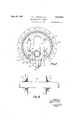
- Figure 2 is a side elevation of the upper part ⁇ of the piston substantially on the line 2-2 of Figures is a vertical section on the line 4-4 of Figure 1 and showing the wheel in side elevation;
- an aeroplane which is intended for use as part of the landing gear oi' an aeroplane. includes a. drop center rim Il. adapted to receive the usual rubbery tire.l
- the rim I0 and the I2 and I4 are preferably made of relatively light metal such as duraluminum.
- Races I6 and I8 form part of anti-friction bearings including balls or the like 20 arranged in cooperating racesA formed in side members 22 and 24 and coniined partly against thrust by side rings '26.
- the side rings 26 are secured by screws 28 or the like to the races I 6 and I8.
- separators 28 of any desired form may be arranged between the balls 2U of the anti-friction bearings.
- the side members 22 and 24 are rigidly spaced apart by upper and lower forgings or castings or similar members 30 and 32, which are arranged between the side members and which are secured thereto by a series of bolts 34 passing through them and through the side members.
- the side members 22 and. 24 are formed with vertlcalzo slots36 through which passes a tubular axle 38.
- the axle 38 is connected by cross pins 4U, or .equivalent means preventing it from turning, to slides 42 arranged in guides 44 riveted or otherwise secured to the side members 22 and 24, thus permitting the axle to move vertically in slots 36 but preventing it from turning.
- the lower member 32 has a vertically arranged cylirrder 46-threaded or otherwise secured at its lower end and immediately below the axle 38, in
- the cylinder 46 also carries a throttling device, such as a tapered plunger 58 passing through an opening in a. bushing 68 ar-I ranged in the head 62 of the hollow piston 54.
- the opening in the bushing 60 communicates by lateral passages 64 with the space in the cylinder 46 above the head 62 oi the piston.
- the tapering of the plunger 58 causes a gradual throttlingof the ow of fluid, and the taper of the plunger is so prop ortioned with respect to the opening in bushing 60 that a constant hydraulic pressure is maintained throughout the Working stroke of the piston Eli, thus absorbing the maximum energy of impact with a minimum strain on the entire structure.
- FIG. 3 is shown one means of introducing oil or other fluid into the above-described novel shock absorbing means.
- a head 'Ml closing the end of the hollow axle 3&3 while some distance fromvthe end of the axle there is arranged a block 'E2 of wood or other material, thus forming a chamber 'M in the end of the axle communicating by an opening 'it with the inter1or of the oil piston te, and thence through the passages tft to the cylinder tti.
- a check valve 'i6 of any usual and desired form is provided in the head l@ for introducing oil or other fluid into the chamber 'M and thence into the cylinder Q6.
- ydamping means for absorbing the initial shock of landing Without rebound having ka metering orifice and a device for resiliently supporting the load independent of said orifice effective only after the initial shock of landing has been absorbed.
- a shock absorber of the class described comprising liquid damping means for absorbing initialshocks without substantial rebound, and addi-A tional means for resiliently receiving additional shocks and ineffective during the absorption of said initial shocks.
- a shock absorber of the class described in combination, a cylinder, a piston movably received in said cylinder, liquid damping means for absorbing the initial shock without substantial rebound, and a spring means for resiliently rel straining movements of the piston and effective only after large degrees of movement of the piston Within the cylinder.
- a shock absorber for supporting a Vehicle comprising a casing, a'liquid damping means having an orifice in said casing for absorbing shocks, and a resilient spring device in said casing 'independent of said suddenly for resiliently supporting the load, said liquid damping means acting to restrict rebound of the spring'device.
- a device of the character described including a cylinder and a piston,the latter including a piston-rod restricted to a single central opening in its head to permit displacement of a fluid therethrough and having means above the piston for assisting in restricting the displacement of a fluid through the piston to establish and maintain communication between the contents of the cylinder on both sides of the piston at all times;
- a tapered metering pin Within the cylinder having its upper end extending through the said opening in the piston-head'to provide a space aroundthe tapered metering pin, the Whole arranged in such manner that upon inward movement ofthe piston in the cylinder, the displacement of the fluid below the .piston head is progressively restricted -by the progressively diminishing area of the space in the piston head around the tapered metering pin to control displacement of fluid through the piston head in either direction and upon outward movement of the piston in the cylinder, a rapid displacement of the fluid from above the piston is restricted by the said displacement restricting means above the piston.
- a lwheel including a liquid damping means for absorbing initial shocks without substantial rebound, and additional means for resiliently receiving additional shocks and ineffective during the absorption of said initial shocks.
- a wheel including, a cylinder, a piston movably received in said cylinder, liquid damping means for absorbing an initial'shock without substantial rebound, and spring means for resiliently restraining movements ⁇ of the piston and effective only after large degrees of movement of the piston withinlthe cylinder.
- a wheel including means for initially absorbing the energy of ⁇ an exerted compressive force 4at a substantially constant rate and additional means brought into operation when the rst meanshas :reached a predetermined positioning under the influence of said compressive forces for additionally absorbing energy of'compressive forces.
- an aeroplaneshock absorbing landing gear a wheel including means for initially absorbing the energy of an exerted compressive forcewithout substantial rebound, and additional means brought into operation when the iirst Ameans has reached a predetermined positioning under the influence of said compressive forces for additionallyabsorbing energy of succeeding compressive forces in a resilient manner.
- a wheel including liquid' damping means encased within said wheel for absorbing shocks, .and a resilient spring device for, resiliently supporting the load encased within saidwheel, saidA liquid damping means acting to restrict rebound of the spring device'.
- An aeroplane shock absorbing device comprising a cylinder, and a piston, a piston' rod projecting from the top of said cylinder, a member forming a shoulder on the end of vsaid piston rod, and an annular resilientmember threaded on said rod and adapted to be compressed between said shoulder and cylinder;
- An aeroplane shock absorbing device com prising,cylinder, piston and piston lrod/means for absorbing andjdissipating shock energy
- An aeroplane shock absorbing device com-- prising a support, a cup-shaped cylinder depending from and secured to said support, a ⁇ piston having a central oriilce within said cylinder, a tubulary piston :rod secured to said piston and projecting from the top of said cylinder, an end closure and gland for ⁇ said cylinder and tubular rod, a member forming a shoulder carried by said piston rod on its outer end, and ⁇ a resilient annularl member threaded on said piston rod adapted to resiliently engage said shoulder to absorb shocks.
- An aeroplane shock absorbing device comprising a liquid damping means having reciprocating parts and a liquid chamber for absorbing the initial shock of landing without rebound and a spring device wholly without the liquid chamber and coaxially mounted with respect thereto for resilientlysupporting the load eiective only 4after the initial shock of landing has beenabsorbed.
- a shock absorber of the 'class described comprising cylinder and Apiston liquid damping means for absorbing initial shocks without substantial rebound, and additional means coaxially arranged at one end of said damping means for resiliently receiving vadditional shocks and for supporting the full load, and ineiective during the absorption of said initial shocks 22.
- An aeroplane shock absorbing device comprising a cylinder having a closed lower end,'a
- a shock absorber of the class described comprising liquid dampingI means for absorbing initial shocks without vsubstantial rebound and at a substantially constant rate having telescopic casings and a metering orifice, said casings containing liquid and gas under pressure, and an additional means for resiliently receiving additional shocks and ineffective during obsorpton of said initial shocks.
- liquid damping means for absorbing initial shocks without substantial rebound and at a substantially constant rate, air under pressure in said damping means, and an additional means for resiliently receiving additional shocks and ineiective during the absorption of said initial ⁇ shocks.
- An aeroplane shock absorbing device comprising cylinder and piston liquid damping means for absorbing initial shocks Without substantial rebound, said piston having a hollow piston rod, and additional means coaxially arranged at one end of said damping means and around said 'piston rod for resiliently receiving said additional shocks and for supporting the load, and ineffective during the absorption of said initial shocks.
- An aeroplane shock absorbing device comprising a liquid damping means having reciprocatingparts and a liquid chamber for absorbing the initial shock of landing without rebound, said means comprising a pair of telescopic cylinders one inside the other, a packing means carried by y.the outer cylinder and a piston carried by the inner, and resilient means wholly outside the liquid chamber and carried on the exposed portion of the inner cylinder, said-resilient means adapted to ⁇ be placed under compression only after' initial movement between said telescopic cylin ers.
Description
Allg. 25, 1936. M LADDQN ET AL v 2,052,234 I AEROPLANE LANDING MEANS Filed July 29, 1927 l 5 sheets-sheet 1 ull/11,111,111
INVENTOR /0 IssAc. M. LADDON SIDNEY P. LYON BY ATTORNEY Aug. 25, 1936. M, LADDON ET AL- 2,052,234
AEROPLANE yLANDING MEANS Filed July 29, 1927 3 Sheets-Shee 2 INVENTOR lssAc M. LADDON vSllxniv i? LYON ar f ATTORNEY Aug. 25, 1936. l. M. LADDON ET A1. I AEROPLANE LANING MEANS Filed July 29, 1927 34sheets-sh'eet 3 INVENTOR l lssAc M LAnDoN SmNEY P LYoN ATTORNEY Patented Aug. 25, 14956 PATENroI-Flcs Isaac M. Laddon, Dayton, and Sidney- P. Lyon, Tippecanoe City, Ohio, assignors, 'by `direct and mesne assignments, to Bendix Aviation Corporation, South Bend, Ind., a corporation of Application .mina 1927, serial No. @9,221 Y e 26 claims. (ci. zei- 64) Thisinvention relates to landing gear for aeroplanesandthe like, and is illustrated-as embodied ,in a wheel mounting including novel means for taking' the shock when the aeroplane lands on the ground so that there will be no tendency to A rebound.
, uir
One important feature of thel invention relates to arranging the parts so that there is a single gradual 1vertical movement of the plane with respectto the wheels as the plane landsI after which the load of the plane is transmitted direct- .ly to the wheels while manouvering on the ing in the piston, for gradually throttling the ow of fluid as the piston stroke progresses.
Another feature of the invention relates to ar- K ranging a shock absorbing means such as the .one ,described above inside oi a rotatable hollowwheel thus' giving substantially a stream-line effect" i. Figure 3 is a 'section supporting the plane or other vehicle so 'that-the entire mechanism is housed within the wheel,
which minimizes air resistance.
Other features 'finovelty relate to the construction and mounting ofv the wheel itself, and to other novel arrangements and desirable particular constructions which lwill be apparent from the following description of one illustrative embodiment shown inthe accompanying drawings, in which: v
Figure 1l is a vertical `section through the wheel and the novel shock absorbing means;
Figure 2 is a side elevation of the upper part `of the piston substantially on the line 2-2 of Figures is a vertical section on the line 4-4 of Figure 1 and showing the wheel in side elevation;
1 Figure 5.'is a partial section substantially on the line 5--5 .of --Figure l and showing .the wheel mounting: land Figure 6 is a partial section on the line 6-6 of Figure v5 and showing the axle mounting.
The arrangement illustrated 'in the drawingsd,
and which is intended for use as part of the landing gear oi' an aeroplane. includes a. drop center rim Il. adapted to receive the usual rubbery tire.l
and to opposite sides of which are secured annular disks I2 and I4 to which races I6- and I8 are secured at their inner edges. The rim I0 and the I2 and I4 are preferably made of relatively light metal such as duraluminum.
Races I6 and I8 form part of anti-friction bearings including balls or the like 20 arranged in cooperating racesA formed in side members 22 and 24 and coniined partly against thrust by side rings '26. The side rings 26 are secured by screws 28 or the like to the races I 6 and I8. separators 28 of any desired form may be arranged between the balls 2U of the anti-friction bearings.
The side members 22 and 24 are rigidly spaced apart by upper and lower forgings or castings or similar members 30 and 32, which are arranged between the side members and which are secured thereto by a series of bolts 34 passing through them and through the side members. The side members 22 and. 24 are formed with vertlcalzo slots36 through which passes a tubular axle 38.
'The axle 38 is connected by cross pins 4U, or .equivalent means preventing it from turning, to slides 42 arranged in guides 44 riveted or otherwise secured to the side members 22 and 24, thus permitting the axle to move vertically in slots 36 but preventing it from turning.
The lower member 32 has a vertically arranged cylirrder 46-threaded or otherwise secured at its lower end and immediately below the axle 38, in
the space between the side disks I2 and I4. .The
and secured to the axle 38. Above the bushings 58 there is arranged a block 56 of rubber or the like on which the axle 38 rests when in its lowermost position. The cylinder 46 also carries a throttling device, such as a tapered plunger 58 passing through an opening in a. bushing 68 ar-I ranged in the head 62 of the hollow piston 54. The opening in the bushing 60 communicates by lateral passages 64 with the space in the cylinder 46 above the head 62 oi the piston.
In the operation of the parts described above, when the plane ls on the ground the axle 38 is resting on the block 56 of rubber and the .parts are in the position shown in Figure 1. When the plane rises into the air, however, the weight of the wheel causes it to move downwardly, thus pistonv 54 is drawn downwardly by the axle 38 60 into a position at the lend of cylinder 46. 'Ihis movement may be-very slow so that there is practically no resistanceA to the flowing of the oil or other fluid from above the head 62 of the piston to the space below the head 62.
When the aeroplane lands, the piston 62 is forced suddenly 4downward by the weight of the plane on the axle 38, thus forcing the oil or other :duid very rapidly through they central passage of the bushing 60 and through passages 64 into that part of the cylinder 46 which is above the head 62 of the passage. This movement is so rapid that the passage of the fluid through these restricted spaces is powerfully retarded, thus transforming the kinetic energy acting through the axle 38 into heat,that is, the device acts as a brake efficiently resisting sudden vertical movement of the axle 38 and' forcing it to come gradually to rest on block '56 forming its support in its normal position when on the ground. The tapering of the plunger 58 causes a gradual throttlingof the ow of fluid, and the taper of the plunger is so prop ortioned with respect to the opening in bushing 60 that a constant hydraulic pressure is maintained throughout the Working stroke of the piston Eli, thus absorbing the maximum energy of impact with a minimum strain on the entire structure.
In Figure 3 is shown one means of introducing oil or other fluid into the above-described novel shock absorbing means. As shown in this figure, there may be a head 'Ml closing the end of the hollow axle 3&3 while some distance fromvthe end of the axle there is arranged a block 'E2 of wood or other material, thus forming a chamber 'M in the end of the axle communicating by an opening 'it with the inter1or of the oil piston te, and thence through the passages tft to the cylinder tti. A check valve 'i6 of any usual and desired form is provided in the head l@ for introducing oil or other fluid into the chamber 'M and thence into the cylinder Q6. 'While we prefer to fill the piston 36 and the chamber ill substantially full of a non-compressible fluid such as oil, it is feasible to fill the cylinder iii nearly full of such a non-compressible fluid and then to introduce highly compressed air or the like into the upper part of the cylinder i6 and into the chamber lll.
While one illustrative embodiment of the invention has been described in detail, it is not our intention to limit the scope of the invention to that particular embodiment or otherwise than by the terms of the appended claims.
We claim: v
1. In combination in an aeroplane shock absorber for landing chassis, a liquid. ydamping means for absorbing the initial shock of landing Without rebound having ka metering orifice and a device for resiliently supporting the load independent of said orifice effective only after the initial shock of landing has been absorbed.
2. In combination in an aeroplane shock`absorber, a casing, a liquid damping means therein for absorbing the major initial shock of landing without rebound, and a resilient device therein for resiliently supporting the load, and effectivey to resiliently support Mthe load only after -the major initial shock of the landing has been absorbed by said liquid damping means.
3. A shock absorber of the class described comprising liquid damping means for absorbing initialshocks without substantial rebound, and addi-A tional means for resiliently receiving additional shocks and ineffective during the absorption of said initial shocks.
4. In a shock absorber of the class described, in combination, a cylinder, a piston movably received in said cylinder, liquid damping means for absorbing the initial shock without substantial rebound, and a spring means for resiliently rel straining movements of the piston and effective only after large degrees of movement of the piston Within the cylinder.
5. Ina device of the class described adapted to absorb the energy of exerted compressive forces, means for initially absorbing the energy of an exerted compressive force at a substantially constant rate, an additional means brought into operation when the first means has reached a predetermined positioning under theinfluence of said compressive forces for additionally absorbing energy of'compressive forces.
6.In a device of the class described adapted to absorb the energy of exerted compressive forces, means for initially absorbing the energy of an exerted compressive force without substantial rebound, and additional meansbrought into operation when the first means has reached a predetermined positioning under the influence of said compressive forces for additionally absorbing energy of succeeding compressive forces in a resilient manner.
7. A shock absorber for supporting a Vehicle comprising a casing, a'liquid damping means having an orifice in said casing for absorbing shocks, and a resilient spring device in said casing 'independent of said orice for resiliently supporting the load, said liquid damping means acting to restrict rebound of the spring'device.
8. A device of the character described including a cylinder and a piston,the latter including a piston-rod restricted to a single central opening in its head to permit displacement of a fluid therethrough and having means above the piston for assisting in restricting the displacement of a fluid through the piston to establish and maintain communication between the contents of the cylinder on both sides of the piston at all times;
a tapered metering pin Within the cylinder having its upper end extending through the said opening in the piston-head'to provide a space aroundthe tapered metering pin, the Whole arranged in such manner that upon inward movement ofthe piston in the cylinder, the displacement of the fluid below the .piston head is progressively restricted -by the progressively diminishing area of the space in the piston head around the tapered metering pin to control displacement of fluid through the piston head in either direction and upon outward movement of the piston in the cylinder, a rapid displacement of the fluid from above the piston is restricted by the said displacement restricting means above the piston.
9. In an aeroplane shock absorbing landing. gear, a Wheelv including a liquid damping ymeans gear, a wheel including a liquid damping means 76 2,052,211.: therein for absorbing the major initial 'shock of landing yithout rebound, and a resilientlde.- vice therein for resiliently supporting the load, and effective' to resiliently support theload only after the major initial shock of landing has been absorbed by'said liquid damping means.
12. In an aeroplane shock absorbing landing gear, a lwheel including a liquid damping means for absorbing initial shocks without substantial rebound, and additional means for resiliently receiving additional shocks and ineffective during the absorption of said initial shocks.
13. In an aeroplane shock absorbing 'landing gear, a wheel including, a cylinder, a piston movably received in said cylinder, liquid damping means for absorbing an initial'shock without substantial rebound, and spring means for resiliently restraining movements` of the piston and effective only after large degrees of movement of the piston withinlthe cylinder.
14'. In an aeroplane shock absorbing landing gear, a wheel including means for initially absorbing the energy of `an exerted compressive force 4at a substantially constant rate and additional means brought into operation when the rst meanshas :reached a predetermined positioning under the influence of said compressive forces for additionally absorbing energy of'compressive forces.
15. Inv an aeroplaneshock absorbing landing gear, a wheel including means for initially absorbing the energy of an exerted compressive forcewithout substantial rebound, and additional means brought into operation when the iirst Ameans has reached a predetermined positioning under the influence of said compressive forces for additionallyabsorbing energy of succeeding compressive forces in a resilient manner.
16. In an aeroplane shock absorbing landing r gear, a wheel including liquid' damping means encased within said wheel for absorbing shocks, .and a resilient spring device for, resiliently supporting the load encased within saidwheel, saidA liquid damping means acting to restrict rebound of the spring device'.
17. An aeroplane shock absorbing device comprising a cylinder, and a piston, a piston' rod projecting from the top of said cylinder, a member forming a shoulder on the end of vsaid piston rod, and an annular resilientmember threaded on said rod and adapted to be compressed between said shoulder and cylinder;
18. An aeroplane shock absorbing device com prising,cylinder, piston and piston lrod/means for absorbing andjdissipating shock energy, and
resilient means threaded on said piston rod exterior to said cylinder and coacting with engaglng-means on said rod forresiliently absorbing shock energy,
19. An aeroplane shock absorbing device com-- prising a support, a cup-shaped cylinder depending from and secured to said support, a`piston having a central oriilce within said cylinder, a tubulary piston :rod secured to said piston and projecting from the top of said cylinder, an end closure and gland for `said cylinder and tubular rod, a member forming a shoulder carried by said piston rod on its outer end, and `a resilient annularl member threaded on said piston rod adapted to resiliently engage said shoulder to absorb shocks.
20. An aeroplane shock absorbing device comprising a liquid damping means having reciprocating parts and a liquid chamber for absorbing the initial shock of landing without rebound and a spring device wholly without the liquid chamber and coaxially mounted with respect thereto for resilientlysupporting the load eiective only 4after the initial shock of landing has beenabsorbed. Y
y 21. A shock absorber of the 'class described comprising cylinder and Apiston liquid damping means for absorbing initial shocks without substantial rebound, and additional means coaxially arranged at one end of said damping means for resiliently receiving vadditional shocks and for supporting the full load, and ineiective during the absorption of said initial shocks 22. An aeroplane shock absorbing device comprising a cylinder having a closed lower end,'a
-adapted to resiliently absorb shock.
23. A shock absorber of the class described, comprising liquid dampingI means for absorbing initial shocks without vsubstantial rebound and at a substantially constant rate having telescopic casings and a metering orifice, said casings containing liquid and gas under pressure, and an additional means for resiliently receiving additional shocks and ineffective during obsorpton of said initial shocks.
24. A shock absorber of the class described,
comprising liquid damping means 'for absorbing initial shocks without substantial rebound and at a substantially constant rate, air under pressure in said damping means, and an additional means for resiliently receiving additional shocks and ineiective during the absorption of said initial` shocks.
25. An aeroplane shock absorbing device comprising cylinder and piston liquid damping means for absorbing initial shocks Without substantial rebound, said piston having a hollow piston rod, and additional means coaxially arranged at one end of said damping means and around said 'piston rod for resiliently receiving said additional shocks and for supporting the load, and ineffective during the absorption of said initial shocks. 26. An aeroplane shock absorbing device comprising a liquid damping means having reciprocatingparts and a liquid chamber for absorbing the initial shock of landing without rebound, said means comprising a pair of telescopic cylinders one inside the other, a packing means carried by y.the outer cylinder and a piston carried by the inner, and resilient means wholly outside the liquid chamber and carried on the exposed portion of the inner cylinder, said-resilient means adapted to `be placed under compression only after' initial movement between said telescopic cylin ers. y
ISAAC M. LADDON. SIDNEY P. LYON'.
Priority Applications (1)
| Application Number | Priority Date | Filing Date | Title |
|---|---|---|---|
| US209227A US2052234A (en) | 1927-07-29 | 1927-07-29 | Aeroplane landing means |
Applications Claiming Priority (1)
| Application Number | Priority Date | Filing Date | Title |
|---|---|---|---|
| US209227A US2052234A (en) | 1927-07-29 | 1927-07-29 | Aeroplane landing means |
Publications (1)
| Publication Number | Publication Date |
|---|---|
| US2052234A true US2052234A (en) | 1936-08-25 |
Family
ID=22777883
Family Applications (1)
| Application Number | Title | Priority Date | Filing Date |
|---|---|---|---|
| US209227A Expired - Lifetime US2052234A (en) | 1927-07-29 | 1927-07-29 | Aeroplane landing means |
Country Status (1)
| Country | Link |
|---|---|
| US (1) | US2052234A (en) |
Cited By (1)
| Publication number | Priority date | Publication date | Assignee | Title |
|---|---|---|---|---|
| US2939262A (en) * | 1958-01-14 | 1960-06-07 | Sr John A Orr | Lawn edger |
-
1927
- 1927-07-29 US US209227A patent/US2052234A/en not_active Expired - Lifetime
Cited By (1)
| Publication number | Priority date | Publication date | Assignee | Title |
|---|---|---|---|---|
| US2939262A (en) * | 1958-01-14 | 1960-06-07 | Sr John A Orr | Lawn edger |
Similar Documents
| Publication | Publication Date | Title |
|---|---|---|
| US2959410A (en) | Double stage oleo-pneumatic shock absorber | |
| US2342381A (en) | Liquid damped resilient suspension device for vehicles | |
| US2352351A (en) | Shock absorber | |
| US3533613A (en) | Axially retractable landing gear | |
| US2756989A (en) | Suspension device for vehicles | |
| US2294918A (en) | Retractable undercarriage for airplanes and the like | |
| US3078967A (en) | Shock strut with linear damper | |
| US1918698A (en) | Shock absorbing strut for aeroplanes | |
| US1918699A (en) | Shock absorbing strut for aeroplanes | |
| US1819414A (en) | Shock absorbing device | |
| US2313242A (en) | Shock strut | |
| US2052234A (en) | Aeroplane landing means | |
| US2396318A (en) | Shock absorbing strut for aircraft | |
| US3062485A (en) | Aircraft landing gear for use on catapult aircraft | |
| US3292919A (en) | Aircraft shock absorber | |
| US2698751A (en) | Device for maintaining constant static position for landing gears | |
| US2581856A (en) | Vehicle suspension | |
| US2199880A (en) | Hydraulic shock absorber | |
| US3598207A (en) | Dual mode shock strut | |
| US3653682A (en) | Energy absorbing device | |
| US3540683A (en) | Dual air chambered shock strut | |
| US2368855A (en) | Landing gear | |
| US1791484A (en) | Shock-absorbing and springing mechanism with particular application to aircraft requirements | |
| US2352401A (en) | Shock absorbing strut | |
| US2248865A (en) | Shock absorbing strut |