US2039733A - Electropneumatic brake - Google Patents
Electropneumatic brake Download PDFInfo
- Publication number
- US2039733A US2039733A US669746A US66974633A US2039733A US 2039733 A US2039733 A US 2039733A US 669746 A US669746 A US 669746A US 66974633 A US66974633 A US 66974633A US 2039733 A US2039733 A US 2039733A
- Authority
- US
- United States
- Prior art keywords
- valve
- brake
- valve device
- fluid
- service
- Prior art date
- Legal status (The legal status is an assumption and is not a legal conclusion. Google has not performed a legal analysis and makes no representation as to the accuracy of the status listed.)
- Expired - Lifetime
Links
Images


Classifications
-
- B—PERFORMING OPERATIONS; TRANSPORTING
- B60—VEHICLES IN GENERAL
- B60T—VEHICLE BRAKE CONTROL SYSTEMS OR PARTS THEREOF; BRAKE CONTROL SYSTEMS OR PARTS THEREOF, IN GENERAL; ARRANGEMENT OF BRAKING ELEMENTS ON VEHICLES IN GENERAL; PORTABLE DEVICES FOR PREVENTING UNWANTED MOVEMENT OF VEHICLES; VEHICLE MODIFICATIONS TO FACILITATE COOLING OF BRAKES
- B60T13/00—Transmitting braking action from initiating means to ultimate brake actuator with power assistance or drive; Brake systems incorporating such transmitting means, e.g. air-pressure brake systems
- B60T13/10—Transmitting braking action from initiating means to ultimate brake actuator with power assistance or drive; Brake systems incorporating such transmitting means, e.g. air-pressure brake systems with fluid assistance, drive, or release
- B60T13/66—Electrical control in fluid-pressure brake systems
- B60T13/665—Electrical control in fluid-pressure brake systems the systems being specially adapted for transferring two or more command signals, e.g. railway systems
Definitions
- a further object of the invention is to provide an electrical control system for pneumatic brake equipment having the above noted characteristics, wherein the electro-magnet valve device is controlled by a two wire or conductor electrical circuit.
- a further object of the invention is to provide an improved electrically controlled triple valve device for controlling the pneumatically actuated brake equipment, and an improved and simplified electrical brake switch device for controlling the operation of said electrically controlled triple valve device.
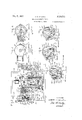
- FIG. 1 is a diagrammatic view of an electropneumatic brake equipment embodying features of my invention
- Fig. 2 is a diagrammatic view, mainly in section, of an improved electrical brake switch device for controlling the electro-pneumatic brake equipment shown in Fig. 1;
- Fig. 3 is a plan view, partially in section, of the brake switch device shown in Fig- 2;
- Fig 4 is a transverse section through the brake switch device taken on the line 44 of Fig. 2;
- Figs. 5, 6, and 7 are transverse sections through the brake switch taken on the line 5-5 of Fig. 2, showing the switch operating handle and shaft in different operative positions, respectively;
- Fig. 8 is a diagrammatic View, mainly in section, of the electrically controlled triple valve device embodying features of the invention, and the usual pneumatically controlled triple valve device associated therewith, the parts being shown in the positions occupied thereby when the brake switch is in release position; and
- the brake equipment includes the train conductors I I and I2 and the usual brake pipe I3, all of which extend throughout the length of the train.
- On the locomotive are mounted the usual main reservoir I4 and associated feed valve device I5, brake valve device !6, and branch pipe I! for connecting the brake valve device I6 to the brake pipe I3.
- Also carried upon the locomotive is an improved electrical brake switch device I8, and associated therewith is an electro-magnet valve device I9, that is connected to the brake valve device I6 by a branch pipe 2
- each car of the train including the ca.- boose, are mounted an auxiliary reservoir 28, a pneumatically controlled triple valve device 29 connected to the brake pipe by a branch pipe 3I and to the auxiliary reservoir by a pipe 32, a brake cylinder 33 connected to the triple valve device 29 by a pipe 34, and an electrically controlled triple valve device 35 that is connected to the auxiliary reservoir by a pipe 36 and to the exhaust port of the triple valve device 29 by a pipe 3?, the electrical triple valve device 35 being provided with the usual retainer valve: device 38 to which it is connected by a pipe 39.
- each electrically controlled triple valve device 35 is provided with a magnet valve device 4 I, the winding of which is connected across the train conductors II and I2 by branch conductors 42 and 43, respectively.
- the electrical brake switch device I8 and appurtenant devices are shown in detail in Figs. 2 to '7 and comprise a metal casing 5
- the operating handle 56 is provided with a spring-pressed movable stop pin 51, Figs. 2 and 3,
- a notch 58 in the periphery of a stop disc 59 that is secured to the casing 5I.
- the bottom edge of the notch is provided midway between the stop shoulders BI and 62 on the disc, with a notch 63 for receiving the stop pin 51 for yieldingly retaining the operating handle 56 and its associated shaft 53 and switch 52 in lap position.
- the handle and switch drum are arrested in service and release position by engagement of the stop pin 51 with the stop shoulders 6
- Insulating plates 65 and 66 are secured in and close'openings 61' in the wall of the casing 5
- the switch drum 52 is in central or lap position and on its left side is provided with two switch contacts 8i and 82, the former being adapted to engage and conductively connect the contacts II and I2, and the latter beingadapted to engage and conductively connect the contacts 13 and I4, when the drum 52 is in release'position.
- the drum is provided on its right side with two bridging switch members 83 and 84, the former beingadapted to engage and conductively connect contacts I5 and I6 and the latter being adapted to engageand conductively connect contacts I1 and I8 when the drum 52 is in service position.
- the contacts II and I5 are conductively con nected by a conductor 85 which is connected to the positive pole terminal 86 of a battery 81, or other source of direct current, which supplies current to the electrical control circuit including the train conductors II and I2, and contacts 13 and I! are conductively connected by a conductor 88 that is connected to the negative terminal 89 of said battery 81.
- the train conductors II and I2 are connected to the battery or direct current source when the brake switch'device is in service position and interlocking means prevents the movement of the operating handle from service position for a predetermined time after movement thereof to service position.
- the train conductors II and I2 are also connected to the battery or source of direct current for a predetermined time when the operating handle 56 and switch drum 52 are in release position, and are disconnected from said source of current after the said predetermined time has expired.
- the train conductors are disconnected from the source of power when the brake switch device is in lap position.
- the switch drum 52 of the brake switch device I8 is retained in service position for a predetermined time after movement into service position, by an electrically controlled interlocking device which comprises a chamber 9
- an electrically controlled interlocking device which comprises a chamber 9
- the magnet valve device I9 comprises a winding 99 for operating oppositely seating valves IOI and I 02, the valve IOI being contained in a chamber I03 which is open to the atmosphere through an atmospheric passage I04 and the valve I02 being contained in a chamber I05 to which the pipe 2I leading from the feed valve device I5 is connected. Also contained in the chamber I05 is a helical spring I06, the pressure of which tends to seat valve I02 and unseat valve IOI.
- valves IOI and I02 there is a chamber I01 which is connected through passage and pipe 23 to chamber 98 at the left face of the piston 92.
- valve IOI When the winding 99 is energized, as when the brake switch device is in service position, valve IOI is seated and valve I02 is unseated. Fluid under pressure is then supplied from the feed valve device I5 to the chamber 98 at the left face of the piston 92 through pipe 2
- the winding 99 of magnet valve device I9 is energized only when the brake switch handle 56 and switch drum 52 are in service position, where it is held for a predetermined time, depending upon the operation of delayed action relay devices controlled by said switch drum, which cause deenerg'ization of the magnet valve device I9 and release of the locking rod 93 from engagement with the shaft 53.
- the relay switch device 25 comprises a bridging switch member II4 for conductively connecting contacts H5 and H6 and which is normally retained in closed position by gravity or by a spring, not shown. The bridging switch member is moved to open position out of engagement with said contacts when a winding II! of the relay device is energized.
- the delayed action relay switch devices 26 and 2'! are of the time delay type, the device 26 having a bridging switch member I I8 for conductively engaging contacts H9 and I2I and which is.nor-
- the bridging switch member H8 is moved to closed position when the winding I22 thereof is energized for a predetermined time, depending upon the inductive impedance of the winding, which may be proportioned to suit operating conditions, and serves to delay movement of the switch member I I8 to closed position until a pre determined time has elapsed after energization of the operating winding I22.
- the relay device 21 is similar to the relay device 26 and comprises a bridging switch member I23 for conductively engaging contacts I24 and I25, the said switch member being normally in open position and adapted to be closed, in the manner of the relay switch device 26, a predetermined time after its operating winding I26 is energized.
- bridging switch member 83 on the drum conductively engages contacts 15 and 16 and bridging switch member 84 on the drum conductively engages contacts 11 and 18.
- the flattened portion 95 on the shaft 53 is then aligned with the notch 95 in the forked rod.
- the train wires II and I2 are connected to the source of direct current or the battery 81, the positive terminal 86 thereof being connected to the train wire I I through conductor 85, contact 15, bridging switch member 83, contact 16, conductors I21 and I28, and the negative terminal 89 of the battery being connected to the train wire I2 through conductor 88, contact 11, bridging switch member 84, contact 18, and conductors I29 and I3I.
- winding 99 of the magnet valve device I9 is then connected across the energized conductors I I and I2 through conductor I28, winding 99, conductor I32, contact H6 of the relay switch device 25, bridging switch member II4, contact H and conductor I3I.
- energization of the winding 99 causes fluid under pressure to be supplied to chamber 98 and the piston 92 forces the forked rod 93 into locking engagement with the shaft 53.
- the shaft 53 remains locked in service position so long as the winding 99 is energized, or until the circuit through the winding is interrupted by movement of the bridging switch member II4 to open position.
- the operation of the bridging switch member H4 is controlled by the delayed action relay devices 26 and 21, which function in the following manner.
- the winding I26 of the relay switch device 21 is energized through conductors I28 and I21, winding I26, conductors I29 and I3I.
- the bridging switch member I23 engages contacts I24 and I25 and thereby connects the winding I22 of the relay switch device 26 across the then energized train conductors I I and I2, through conductors I28 and I21, conductor I33, contact I24, bridging switch member I23, contact I25, conductor I34, winding I22, and conductors I35 and I3I.
- Energization of the winding I22 causes the bridging switch member II8 to move to closed position in engagement with contacts I I9 and I2 I, a predetermined time after the winding I22 is energized, due to the impedance of the winding of the relay switch device 26.
- Closure of the bridging switch member I I8 connects the winding II1 of the relay switch device 25 across the then energized conductors II and i2, and the winding is energized through conductors 128, I21, and I33, contact I24, closed bridging switch member I23, contact I25, eonductors I34 and I38, contact II9, closed bridging switch member H8, contact I2I, conductor I31, winding H1, and conductors I36 and I3I.
- Deenergization of the magnet valve device I9 permits the spring I88 thereof to seat the valve I02 and unseat the valve IIlI.
- the valve I82 seated With the valve I82 seated, the flow of fluid from the feed valve device 55 to the chamber 98 at the left of the piston 92 is cut off, and with the valve I8I unseated, com munication is established from the chamber 98 to the atmosphere through pipe and passage 23, chamber I61, past the open valve IOI, chamber 63 and atmospheric passage I84.
- Fluid under pressure may then flow to atmosphere from the chamber 98 and the consequent reduction in fluid pressure permits the spring 90 to force the piston to its left position and to withdraw the forked rod 93 from the shaft 53, thereby releasing the shaft for subsequent rotation toward lap or release position.
- engages contacts H and 12 and the bridging switch member 82 engages the contacts 13 and 14.
- the battery 81 is then connected to the train conductors II and I 2, the positive terminal 86 of the battery being connected to the conductor II through the contact II, bridging switch member 8i, contact 12, conductors MI and I42, and the negative terminal 89 being connected to the train conductor i2 through contact 13, bridging switch member 82, contact 14, conductor I43, contact I44 of a normally closed delayed action relay switch device I45, the bridging switch member I46 of said relay device, contact I41 and conductor I48.
- the winding I49 of the delayed action relay device M5 is connected across the battery 81, through positive terminal 86, contact 1I, bridging switch member 8
- the impedance of the winding I49 of the delayed action relay device M5 is so proportioned that it will delay opening movement of the normally closed bridging switch member I46 for 'sition without interference.
- the brake switch device I8 in the form of an interlock mechanism, to prevent movement of the operating handle 56 and switch drum 52 from release-lap position to release position without first moving the operating handle 56 and the switch drum 52 to service position.
- the interlocking mechanism employed is shown in Figs. 5, 6, and 7 and is somewhat similar to the interlock mechanism disclosed in U. S. Patent 1,810,547, issued June 16, 1931 to John H. Woods.
- the interlock mechanism comprises a collar I55 fixed to the lower end of the shaft 53 and disposed within the casing 5i, the said collar having a notch I56 in the peripheral edge thereof and two radially extending pins -I 51 and I 58 which are fixed thereto.
- a dog member I59 is mounted within the casing 5I for oscillation about a pivot shaft I6I fixed to the end wall 54 of the casing 5
- An over-center spring device serves to move the dog member to either of its two operative positions, as shown in Figs. 5 and 6, and yieldingly retains it in such a position until forced out of such position by the pins I51 and I58 fixed to the collar 'I55, in the manner to be described.
- the over-center spring device comprises a helical spring I62 surrounding a spring retainer rod I63 having one end mounted in a recess I64 in the casing 5I for longitudinal and angular movement, and its other end pivotally connected to said dog member I59 by a pivot pin I65.
- the spring engages a seat I66 on the casing 5I and a shoulder I61 on the retainer rod I63.
- the operating handle is I almost in release position and the pin I51 is engaging the shoulder I69.
- Final movement of the operating handle to release position will rotate the dog member counter-clockwise and it will be forced tothe position shown in Fig. 5.
- the operating shaft 53 may then be turned counter-clockwise to service position, shown in Fig. 6, wherein it is locked and retained for a predetermined time by the forked interlock rod 93, Fig. 4, in the manner previously described.
- the shaft 53 may be turned to lap position or to release po-
- the pin I51 engages the shoulder I59 on the dog member I59 and "rotates the latter counter-clockwise against the action of the spring I62, until the pivot pin I65 passes below the said center line, at which time the spring expands and forces the dog member operating handle to release position from re- 1ease-lap position, that is, after it has previously been moved directly to lap position from release position without going through service position, it is necessary to first turn the shaft 53 to service position, thereby causing the dog member I59 to be moved to retracted position in the manner described.
- the pneumatic triple valve device 29 comprises a casing having a piston chamber I15,
- the pneumatic triple valve device is of a well known standard construction and. the parts normally are in the release or running position, as shown in Fig. 8, when the brake equipment is being controlled by the electrical control equipment.
- the cavity I83 therein serves to establish communication between the passage and pipe 34 connected to the brake cylinder 33 and the pneumatic triple valve exhaust passage and pipe -31, to be more fully herein described.
- The'pneumatic triple valve device is responsive to variations in brake pipe pressure for effecting the usual control of the brake equipment pneumatically and, therefore, may be controlled in the usual manner by the brake valve device I6 on the locomotive.
- the electrically controlled triple valve device 35 hereinafter called the electrical triple valve device, comprises a casing having a piston chamber I84 containing a piston I85, and a piston chamber I86 containing a piston I81, and having a valve chamber I88 intermediate said piston chambers connected to the auxiliary reservoir 28 by a pipe 36, and containing a main slide valve I89 and an auxiliary or graduating slide valve I9I mounted on and having movement relative to the main slide valve, said valve being operated by the pistons I85 and I81 through a stem I92 integrally connecting said pistons.
- the main slide valve I89 is disposed between stop shoulders I93 and I94 on the stem I92, so spaced that the stem may be moved relatively with respect to the main slide valve.
- the graduating slide valve I9I is so connected to the stem 192 that it moves with it and may lap and uncover ports in the main slide valve, as will here.- inafter appear.
- .a centerin .Qr stop device is mounted comprising .a slidalaly mounted stop member I95 and a spring I95 for yieldingly biasing said stop member toward its extreme left position.
- a similar centering or stop device is mounted within the piston chamber I86 and. comprises a slidably mounted stop member :I 9I and a spring I98 for yieldingly biasing said stop member to.- ward its extreme right position.
- the stop members I95 and I91 are in their extreme left and right positions, respectively, they respectively engage the pistons I85 and I8"! .and yield ingly retain them in central or release position.
- the electrical triple valve device35 is :provided with a magnet valve device 4
- a magnet winding 205 surrounding an armature 206 on the valve stem .201 when energized, causes the valve 20I to engage a seat 208 and close communicationbetween the chamher 202 and a chamber 209 within the casingof the electrical triple valve device having a passage 2
- a spring 2 I2 within the chamber 209 normally presses the valve 20I into engagement with :a valve seat 2I3, as shown in Fig. 8, thus closing communication between the chamber .202 and a chamber 2I4 that is open to the atmosphere through atmospheric port 2 I 5.
- the winding 205 of the magnet valve device. is connected across the train conductors I -I .and I2 by conductors 42 and 43 and isenergized when the train conductors are energized.
- a volume reservoir 2I6 is provided in'the electrical triple valve device casing and a passage 2 l? leads therefrom to the seat 204 for the main slide valve.
- the electrical triple valve device 35 is alsoprovided with a triple valve exhaust closing valve device 2! comprising valve chambers .2I9 and 22I in the casing of the electrical triple valve device, the chamber 2I0 containing a valve piston 222 for making sealing engagement with an annular seat rib 223 for closing communication between chambers 2 I 9 and HI, and the chamber 22I containing a valve 224 yieldinglyconnected to the valve piston 222 by a stem 225, telescoping within a stem 226 and having a slot-and pin lost motion connection thereto.
- the spring 221 within the stem 226 yieldingly holds the .stem'22-5 in extended position with respect to the valve piston 222, as shown in Fig. 8.
- the valve ;224 is adapted to seat upon an annular seat rib1228 and close communication from the exhaustpipe 31 and branch pipe 229 to the chamber 22I.
- the retainer valve device 38 is connected rto the chamber 22I by passage and pipe,:39.
- Fluidunder pressure also flows.from&.the;fee d valve device I5 to the brake valve device I6 throughpipe I and thence; to:th e braker -pipe I3 through branch pipe I'I. Fluid under pressure flows from the brake pipe-I3,. to the triple valve device 29 on each car and the caboose through braneh pipes 3
- fluid .ur der pressure flows from the valve ham e 111 .8 21 the piston mem e through rest icted p rt 23 e-era a ne a ve port12,36 in themain slidevalve I89 and passage zan.
- Thepistons I85 and I8 are of equal area and since the :outerand inner faces of both pistons aresubjected to valve chamber or auxiliary reservoir pressnre, the fluid pressure acting on said pistonsisbalanced and-the stopmembers I95 and I292! the/11.0 .1 1 th pi ton in release position, as shown infig. 8.
- the amount of the brake cylinder pressure developed will be determined by the time the brake switch device is held in service position, the maximum pressure being the pressure of equalization between the auxiliary reservoir and the brake cylinder at the time of the movement of the brake switch device to service position, supplemented to a certain extent by restricted flow of fluid under pressure from the brake pipe through the feed groove I14 past the piston I11 of the pneumatic triple valve device 29.
- valve seat 2I3 With the brake switch device I8 in the servicelap position, the magnet valve device 4
- the main slide valve I89 occupies the same position as it did when the parts were in service position. Therefore, the volume reservoir remains connected to atmosphere through the cavity 245 in the main slide valve.
- the electrical brake switch is moved from service-lap position to service position, where it is again retained for a predetermined period of time by the forked rod 93 controlled by the magnet valve device I9.
- is again energized and causes the valve 20I to move into engagement with the valve seat 208 and to open the valve seat 2I3 so that fluid may flow from the piston chamber I84 to the atmosphere through passage 231, port 244 in the main slide valve I89, cavity 232 in the graduating slide valve I9I, port 23I in the main slide valve, passage 203, chamber 202, past the open valve seat 2 I 3, chamber 2 l 4 and atmospheric passage 2I5, thereby reducing the pressure in the chamber I84.
- the pressures on the outer faces of the pistons I85 and I81 are unbalanced and the higher fluid pressure acting on the outer face of the piston I81 causes the piston to move toward transition position, as shown in Fig.
- the locking mechanism including the forked rod 93, thus insures a service application of the brakes being effected before movement of the brake switch handle to service-lap position can be effected, in order to prevent an undesired release of the brakes by operation of the brake switch device I8.
- the brake switch handle 56 may be returned to lap position, which operation causes deenergization of the magnet valve device 4
- the electrical triple valve piston In making a graduated service application of the brakes, as when fluid under pressure is applied to the brake cylinders after the electrical triple valve device has moved to lap position, as has been previously pointed out, the electrical triple valve piston must move from lap position, as shown in Fig. 10, to transition position and then through release position to service position, as shown in Fig. 9. This operation requires a short time interval for its completion, and it would be undesirable to permit movement of the brake switch handle from service position and consequent deenergization of the magnet valve device 4 I, until after the operation has been completed.
- the locking mechanism including the forked rod 93 and its controlling electromagnet valve device I9 are provided, which devices operate to retain the electrical brake switch device in service position for a predetermined time, in the manner previously described, upon movement of the brake switch operating handle 58 to service position.
- the operating handle 56 of the brake switch device is moved to release position, thereby causing energization of the train conductors II and I2 and the magnet valve device M, in the manner previously described.
- the pistons and valves of the electrical triple valve device move first to transition position before moving to release position, as shown in Fig. 8.
- the magnet valve II is automatically deenergized by the opening operation of the relay I85, which opening operation occurs some time after the slide valves have reached transition position and before they reach release position, and thus since the valve 29I seats on valve seat 2 I3, no venting of the piston chamber I88 occurs when the slide valves reach release position, such as occurs when the brake switch handle 58 is moved to and held in service position. Consequently the slide valves remain in release position, as shown in Fig. 8, andas a result, fluid under pressure from chamber 2I9 above the exhaust valve piston 222 exhausts to atmosphere by way of passage 2, cavity 245 in the main slide valve I89, restricted passage 241, and passage 2%.
- the brake switch handle 56 is held in release position or moved to release-lap position after the electrical triple valve device has moved to release position, the fluid under pressure in the brake cylinder is fully exhausted to atmosphere and the brakes fully released.
- the brake switch handle 56 is held in release position long enough to secure the desired reduction in brake cylinder pressure, after which the brake switch handle 56 is moved to service position and, immediately upon being released by the forked rod 93, to lap position. Movement of the slide valve mechanism of the electric triple valve device to service position is effected upon the energization of magnet valve device 4
- the brake switch handle 56 is again moved from service-lap position to release position and held there long enough to secure the desired reduction in brake cylinder pressure. Movement of the electrical triple valve device to lap position to cut off further exhaust of fluid under pressure from the brake cylinder is then eifected, as before, by movement of the brake switch handle 56 to service position, and, immediately'uponrelease of the handle by forked rod 93, to lap position.
- Successive movements of the brake switch handle 56 may be repeated until the brake cylinder has been completely vented and the brakes thereby fully released.
- the brake switch handle 56 may then be allowed to remain in release position or moved to release-lap position without any effect.
- the brake switch handle 56 is moved directly to lap position without first being moved through service position, the brake switch device It! is said to be in running-lap or release-lap position, as distinguished from a service-lap position thereof wherein the electrical triple valve is in lap position.
- the interlocking mechanism comprising dog member I59 and collar I55 is provided for the purpose of preventing and functions only to prevent movement 01 the brake switch device I8 to release position thereof from running-lap or release-lap position thereof, without first being moved through service position, it being adapted, however, to permit movement of the brake switch device I8 from service-lap position thereof directly to release position thereof without first being moved through service position.
- the train equipment includes an electrical triple valve device that may be elec trically controlled by timed impulses of electrical current supplied to a magnet valve device for effecting service application of the brakes, release of the brakes, graduated service application of the brakes, graduated release of the brakes, and a lap condition of the brakes.
- a brake switch device is provided for controlling the operation of the electrical triple valve device through the magnet valve device, the switch device being movable to three operative positions, namely, release, lap, and service position. If the brake switch device is moved to lap position from release position, it is said to be in release-lap position, and if it is moved to lap position from service position, it is said to be in service-lap position.
- the magnet valve device on the electrical triple valve device When the brake switch device is in lap position, the magnet valve device on the electrical triple valve device is deenergized ill and when the brake switch device is in service position, a circuit through the electro-magnet valve device on the electrical triple valve device is energized and a magnet valve device is also energized for operating an electrically controlled interlocking mechanism on the brake switch device for retaining the brake switch device in service position and consequently the circuit through the magnet valve device on the electrical triple valve device closed for a predetermined time after the operating handle has been moved to the service position.
- the controlling magnet valve device for the electrical triple valve device When the brake switch device is in release position, the controlling magnet valve device for the electrical triple valve device is held energized for a predetermined time by a delayed action relay switch device and then deenergized thereby.
- the electrical triple valve device is provided with fluid actuated, normally balanced pistons for operating the main and graduating slide valves to release, lap, and service positions, and the fluid under pressure for actuating said pistons is controlled by the said magnet valve device and said valves.
- the magnet valve device is movable to one operative position when energized and to another position when deenergized. The fluid under pressure acting on the said pistons is thus controlled to effect proper movement of the pistons and associated slide valves to said operative positions as desired.
- the nature of the electrical triple valve device is such, that when the operating handle of the brake valve device is moved to service position, the controlling magnet valve device is energized and causes the valve to move to service position, in which position fluid under pressure is caused to flow from the auxiliary reservoir to the brake cylinder to effect an application of the brakes and the exhaust passage from the brake cylinder to the atmosphere is closed.
- the magnet valve device When the brake switch handle is moved to service-lap position, the magnet valve device is deenergized and the slide valves are moved by the pistons to lap position in response to a change in pressure on the pistons occasioned by the shift in position of the magnet valve device.
- the brake switch device In effecting a reapplication of the brakes from a service-lap position of the brake switch device, the brake switch device is moved to service position where it is maintained at least a predetermined time, movement of the electrical triple valve device being effected in such manner that it moves from service-lap position through a transition position and through release position to service position, the extent or degree of the reapplication being determined by the length of time the brake switch handle is retained in service position before being returned to service-lap position.
- the interlocking mechanism functions to prevent an undesired release of the brakes by operation of the brake switch device to service position from service-lap position by holding the brake switch handle in service position a sufficient length of time to insure its movement through transition position and past release position. If return movement of the brake switch device to service-lap position were permitted prior to the electrical triple valve device reaching service position, as for example, While it were yet in release position, and undesired release of the brakes would be eifected.
- the brake switch device is moved directly to release position
- electrical triple valve device is accordingly operated, upon energization of its controlling magnet valve device, to move through transition position to release position where it stops becauseof the deenergization of the controlling magnet valve device by the opening of the delayed action relay switch device.
- the brake switch device is moved to release position from service-lap position, as above described, held there long enough to secure the desired reduction in brake cylinder pressure, and then moved to service position, whence after being released by the locking mechanism above described, it is returned to service-lap position.
- a locking mechanism comprising a togglebiased dog member which cooperates with a notched collar secured to the operating shaft of the brake switch device.
- This locking mechanism prevents movement of the brake switch device from release-lap position to release position without first being moved through service position, it being adapted to permit movement of the brake switch device from release-lap position to service position for freeing the brake switch device to move thereafter to release position.
- the apparatus above described is capable of effecting, by proper manipulation of the brake switch device, service, graduated service, release,
- a fluid operated brake means the combination with a fluid operated valve device for controlling the fluid supply to the brake means and having an operating cycle having more than two operative positions for efiecting a predetermined cycle of operating conditions in the brake means, of a valve means for controlling said valve device and reciprocable between two operative positions, and means whereby repeated movement of the valve means alternately to its operative positions effects movement of the pneumatically operated valve device successively to its operative positions in the operating cycle thereof.
- an electrically controlled fluid operated brake means the combination with a fluid operated valve device for controlling the fluid supply to the brake means and having an operating cycle having more than two operative positions for effecting a predetermined cycle of operative conditions in the brake means, of an electrically controlled valve means for controlling said valve de- 7 vice and reciprocable between two operative positions, and means whereby repeated movement of the electricallycontrolled valve means alternately to its operative positions effects movement of the pneumatically operated valve device successively to its operative positions in the operating cyc1ethereof.
- a fluid operated brake means the combination with a fluid operated valve device for controlling the fluid supply to the brake means and having an operating cycle having more than two operative positions for eiTec ting a predetermined cycle of operating conditions in the brake means, of a valve means for controlling said valve device and reciprocable between two operative positions, means whereby repeated movement of the valve means alternately to its operative positions effects movement of the pneumatically operated valve device successively to its operative positions in the operating cycle thereof, and a manually actuated automatically operated control means for effecting a movement of the valve means from one operative position to its other operative position a predetermined time after the control means has been actuated manually.
- a fluid operated brake means the combination with a fluid operated valve device for controlling the fluid supply to the brake means and having an operating cycle having more than two operative positions for effecting a predetermined cycle of operating conditions in the brake means, of a valve means for controlling said valve device and reciprocable between two operativepositions, means whereby repeated movement of aosa'zss the valve means alternately to its operative positions efiects movement of the pneumatically operated valve device successively to its operative positions in the operating cycle thereof, manually actuated control means for the valve means for efiecting the movement of the valve means from one operative position to its other operative position, and means automatically actuated a predetermined time after movement of the manually actuated control means for effecting the movement of the valve means from said other operative position to the said one operative position.
- a fluid operated brake means the combination with a fluid operated valve device for controlling the fluid supply to the brake means and having an operating cycle comprising a plurality of distinct operative positions for eflecting a predetermined cycle of operating conditions in the brake means, of a valve means for controlling said valve device and reciprocable between two operating positions for efiecting the operation of the said valve device successively to its operative positions in its operating cycle, and a controlling means for said valve means adapted to automatically effect an operation of the said valve means a predetermined time after it has effected an operation of the said valve means.
- a fluid operated brake means for controlling the fluid supply to the brake means and having an operating cycle comprising a plurality of distinct operative positions for effecting a predetermined cycle of operating conditions in the brake means, of a valve means for controlling said valve device and reciprocable between two operating positions for eflecting the operation of the said Valve device successively to its operative positions in its operating cycle, and a manually and automatically actuated control means for said valve means adapted to be automatically actuated to efiect an operation of the said valve means a predetermined time after it has-effected an operation of the said valve means by a manual actuation.
- a fluid operated brake means the combination with a fluid operated valve device for controlling the fluid supply to the brake means and for effecting different operating conditions in said brake means when moved to different operating positions, of a valve means for controlling the delivery of fluid to the said valve device for effecting a successive movement of the said valve device from one position to another of its several operative positions upon each movement of said valve means, control means for moving the valve means to its respective operating positions, and means for controlling operation of the said control means for automatically regulating the time interval between successive .movements of said valve means.
- a fluid operated brake means the combination with a fluid operated valve device for controlling the fluid supply to said brake means, for effecting different operating conditions in said brake means when moved to different operating positions and a valve means for controlling the fluid under pressure acting on said valve device for effecting step by step movement of said valve device to its respective operative positions upon movements of said valve means to its respective operating positions, means for moving said valve means to its operative positions, and means for controlling the last said means and for automatically regulating the time interval between successive movements of said valve means.
- 'A'valve “device'for controlling afluid'actuated brake means supplied with actuating fluid from a source of supply of fluid under pressure comprising a fluid actuated valve means for controlling the delivery of fluid from the said supply to the said brake means and movable through a predetermined cycle of operations to effect a cycle of more than two operating conditions in the brake means, and a single valve device having two operative positions and cooperating with the said valve means for effecting a cycle of operation of the valve means when repeatedly moved alternately to its respective operating positions.
- a valve device for controlling a fluid actuated brake means supplied with actuating fluid from a source of supply of fluid under pressure comprising a fluid actuated valve means for controlling the delivery of fluid from the said supply to the said brake means and movable through a predetermined cycle of operations to eflect a cycle of more than two operating conditions in the brake means, a single valve device having two operative positions and cooperating with the said valve means for efiecting a cycle of operation of the valve means when repeatedly moved alternately to its respective operating positions, and means for controlling the operation of the single valve device.
- a valve device for controlling a fluid actuated brake means supplied with actuating fluid from a source of supply of fluid under pressure comprising a fluid actuated valve means for controlling the delivery of fluid from the said supply to the said brake means and movable through a predetermined cycle of operations to effect a cycle I ated brake means supplied with actuating fluid from a source of supply of fluid under pressure, comprising a fluid actuated valve means for controlling the delivery of fluid from the said supply to the said brake means and movable through a predetermined cycle of operations to effect a cycle of more than two operating conditions in the brake means, a single valve device having two operative positions and cooperating with the said valve means for effecting a cycle of operation of the valve means when repeatedly moved alternately to its respective operating positions, and current responsive automatically controlled means for effecting operations of the single valve device in timed relation.
- a valve device for controlling the operation of a fluid actuated brake means having service, lap, and release operating conditions constituting a cycle of brake operation comprising a fluid pressure actuated valve device movable to service, lap, and release positions for respectively eiiecting the said operating conditions of the said brake means, a valve means having two operative positions for controlling the fluid acting on said valve device to effect movement of the said valve device, and means including means controlled by the said valve device and the said valve means for effecting movement of the said valve device to its respective operative positions successively upon each change in pressure occasioned be the the manually operative means out of the said position for a certain uniform length of time.
- brake controlling means operably responsive to electrical impulses for controlling the brakes, means manually operative to a position for effecting the imposition of electrical impulses on the brake controlling means, and means, effective upon operation of said manually operative means to said position, for resisting operation of the manually operative means out of the said position and, upon the elapse of a certain uniform length of time, to be ineffective to resist operation of the manually operative means out of the said position.
- brake controlling means operably responsive to electrical impulses for controlling the brakes, means manually operative to a position for effecting the imposition of electrical impulses on the brake controlling means, means, effective upon operation of said manually operative means to said position, for resisting operation of the manually operative means out of the said position, and means, controlling said resisting means, for rendering it ineffective to resist operation of the manually operative means out of the said position upon the elapse of a certain uniform length of time.
- a brake controlling apparatus the combination with a brake controlling valve device responsive to timed electrical impulses for controlling the brakes, of manually operated means for imposing electrical impulses on said valve de- ;vice, and current responsive means for timing the operation of said manually operated means.
- a brake controlling apparatus the combination with a brake controlling valve device responsive to timed electrical impulses for controlling the brakes, of manually operated means for imposing electrical impulses on said valve device, and current responsive means for con trolling the operation of said manually operated means for insuring timed operation of said man ually operated means.
- a brake apparatus the combination with a brake controlling means operatively responsive to electrical impulses for controlling the brakes, of manually operable means operable to a position for effecting the imposition of an electrical impulseon said brake controlling means, and means, effective when said manually operable means is operated to said position, to prevent movement of said manually operable means out of said position until after the expiration of a predetermined time.
- a brake apparatus the combination with a brake controlling means operatively responsive to electrical impulses for controlling the brakes, of manually operable means operable to a position for effecting the imposition of an electrical impulse on said brake controlling means, locking means operative when said manually operable means is operated to said position to prevent movement of said manually operable means out of said position, and means effective a predetermined time after said manually operable means is moved to said position for rendering said looking means ineffective to prevent movement of said manually operable means out of said position.
- a brake apparatus the combination with a brake controlling means operatively responsive to electrical impulses for controlling the brakes, of manually operable means operable to a position for effecting the imposition of an electrical impulse on said brake controlling means, and means, effective a predetermined time after said manually operable means is operated to said position, to interrupt the electrical impulse.
- a brake apparatus the combination with a brake controlling means operatively responsive to electrical impulses for controlling the brakes, of manually operable means operable to two different positions for effecting the imposition of electrical impulses on said brake controlling means, means effective when said manually operable means is operated to one of the said two positions, to prevent movement of said manually operable means out of said position until after the expiration of a predetermined time, and means effective a predetermined time after said manually operable means is operated to the other of the said two positions to interrupt the electrical impulse.
- an electropneumatic brake in combination, a brake controlling valve device, electrically controlled means for effecting the operation of said valve device, manually controlled means movable to two positions for controlling the circuit of said electrically controlled means and having an intermediate lap position, and means for preventing movement of said manually controlled means from lap position to one of said two circuit controlling positions immediately following movement of said manually controlled means from said one circuit controlling position to the lap position.
- a brake controlling valve device electrically controlled means for effecting the operation of said valve device, manually controlled means movable to a release position and to a brake application position for controlling said electrically controlled means and having an intermediate lap position, and means for preventing movement of said manually controlled means from lap position to said release position, immediately following movement of said manually controlled means from release position to lap position.
- an electropneumatic brake in combination, a brake controlling valve device, electroresponsive means adapted when energized to effect operation of said brake controlling valve device, manually operable means movable from an intermediate position in which said electroresponsive means is deenergized into two opposite positions for effecting energization of said electroresponsive means, and means for preventing movement of said manually operable means from said intermediate position to one of said two positions, immediately following movement of said manually operable means from said one of the two positions tosaid intermediate position.
- an electropneumatic brake in combination, a brake controlling valve device, electroresponsive means adapted when energized to effect operation of said brake controlling Valve device, manually operable means movable from an intermediate position in which said electroresponsive means is deenergized into two opposite positions for eflecting energization of said electroresponsive means, and means for preventing movement of said manually operable means from said intermediate position to one of said two positions, immediately following movement of said manually operable means from said one of the two positions to said intermediate position, unless said manually operable means is first moved to the other of said two positions.
- valve means having a plurality of different positions for controlling the operation of the brakes, pressure responsive means for moving the valve means, said pressure responsive means being normally subject to opposing fluid pressures tending to urge the pressure responsive means in opposite directions and movable responsive to variations in the fluid pressures to move the said valve means, and
- valve means operative, when the said valve means is in one position, to vary one of the fluid pressures acting on the pressure responsive means, and operative, when the said valve means is in another position, to vary the other of the fluid pressures acting on the pressure responsive means.
- valve means having a plurality of difierent positions for controlling the operation of the brakes, pressure responsive means for moving the valve means, said pressure responsive means being normally subject to opposing fluid pressures tending to urge the pressure responsive means in opposite directions and movable responsive to variations in the fluid pressures to move the said valve means, means operative at one time to vary one of the fluid pressures acting on the pressure responsive means and at another time to vary the other of the fluid pressures acting on the pressure responsive means, and means conditioned according to the position of said valve means for determining which of the fluid pressures will be varied by operation of the said last means.
- valve means having a plurality of different positions for controlling the operation of the brakes, pressure responsive means for moving the valve means, said pressure responsive means being normally subject to opposing fluid pressures tending to urge the pressure responsive means in opposite directions and movable responsive to variations in the fluid pressures to move the said valve means, and means operative at one time to vary one of the fluid pressures acting on the pressure responsive means and at another time to vary the other of the fluid pressures acting on the pressure responsive means, said valve means being effective in one position thereof to cause the operation of the said last means to vary the said one fluid pressure acting on the pressure responsive means and effective in another position thereof to cause the operation of the said last means to vary the said other of the fluid pressures acting on the pressure responsive means.
Description
May 5, 1936. J. c. MCCUNE- ELECTROPNEUMATIC BRAKE Filed May 6 1953 4 Sheets-Sheet 1 INVENTOR.
JOSEPH (L. MCCUNE 9 %z ATTORNEY.
ma ma May 5, 19336. J. c. M CUNE ELECTROPNEUMATIC BRAKE Filed May 6, 1955 4 Sheets-$heet 2 QUQIKUW muimmw m w IZVVENTOR.
JOSEPH c. MCCUNE ATTORNEY Fig. 8
N] m 32% k m a:
RELEASE /72 232 2 J. C. M CUNE ELECTROPNEUMATIC BRAKE Filed May 6, 1933 4 SheetsShee't 3 INVENTOR.
JOSEPH C. MCUNE A TTORNEY.
y 936. 'J. c. MccuNE ELECTROPNEUMATIC BRAKE Filed May 6', 1933 4 Sheets-Sheet 4 INVENTOR. JOSEPH c. MeCUNE QM. a/W
ATTORNEX Patented May 5, 1936 UNITED STATES PATENT OFFICE ELECTROPNEUMATIC BRAKE Application May 6, 1933 Serial No. 669,746
36 Claims.
This invention relates to electro-pneumatic brake equipment and particularly to fluid actuated train brake equipment that may be controlled pneumatically in the usual manner and electrically.
An object of the invention is to provide an electro-pneumatic brake equipment, wherein a single electro-magnet valve device having two operative positions serves to so control an electrical triple valve, that by simply energizing and deenergizing the magnet in a proper sequence of operation and for regulated periods of time, the electrical triple valve may be moved as desired to the usual operating positions for efiecting the usual operation of the brakes, such as service application, graduated service application, release, and graduated release of the brakes, as well as a lap position wherein the brakes are retained app-lied.
A further object of the invention is to provide an electrical control system for pneumatic brake equipment having the above noted characteristics, wherein the electro-magnet valve device is controlled by a two wire or conductor electrical circuit.
A further object of the invention is to provide an improved electrically controlled triple valve device for controlling the pneumatically actuated brake equipment, and an improved and simplified electrical brake switch device for controlling the operation of said electrically controlled triple valve device. 7
These and other objects of the invention that will be made apparent throughout the further description thereof, are attained by means of the apparatus hereinafter described and illustrated in the accompanying drawings; wherein Fig. 1 is a diagrammatic view of an electropneumatic brake equipment embodying features of my invention;
Fig. 2 is a diagrammatic view, mainly in section, of an improved electrical brake switch device for controlling the electro-pneumatic brake equipment shown in Fig. 1;
Fig. 3 is a plan view, partially in section, of the brake switch device shown in Fig- 2;
Fig 4 is a transverse section through the brake switch device taken on the line 44 of Fig. 2;
Figs. 5, 6, and 7 are transverse sections through the brake switch taken on the line 5-5 of Fig. 2, showing the switch operating handle and shaft in different operative positions, respectively;
Fig. 8 is a diagrammatic View, mainly in section, of the electrically controlled triple valve device embodying features of the invention, and the usual pneumatically controlled triple valve device associated therewith, the parts being shown in the positions occupied thereby when the brake switch is in release position; and
Figs. 9, 10, and 11 are diagrammatic sectional views of the electrically controlled triple valve device, showing the parts of the valve device in service, lap, and transition positions, respectively.
Referring to the drawings, the brake equipment includes the train conductors I I and I2 and the usual brake pipe I3, all of which extend throughout the length of the train. On the locomotive are mounted the usual main reservoir I4 and associated feed valve device I5, brake valve device !6, and branch pipe I! for connecting the brake valve device I6 to the brake pipe I3. Also carried upon the locomotive is an improved electrical brake switch device I8, and associated therewith is an electro-magnet valve device I9, that is connected to the brake valve device I6 by a branch pipe 2| and to an interlocking device 22 on the brake switch I8 by a pipe 23. Also associated with the brake switch device I8 are two relay switch devices 24 and 25, the latter controlling the current supplied fromthe train conductors II and I2 to the electro-magnet valve device I9, and two series related, delayed action relay devices 26 and 21 for controlling certain functions of the brake switch device I8.
Upon each car of the train, including the ca.- boose, are mounted an auxiliary reservoir 28, a pneumatically controlled triple valve device 29 connected to the brake pipe by a branch pipe 3I and to the auxiliary reservoir by a pipe 32, a brake cylinder 33 connected to the triple valve device 29 by a pipe 34, and an electrically controlled triple valve device 35 that is connected to the auxiliary reservoir by a pipe 36 and to the exhaust port of the triple valve device 29 by a pipe 3?, the electrical triple valve device 35 being provided with the usual retainer valve: device 38 to which it is connected by a pipe 39. As will hereinafter appear, each electrically controlled triple valve device 35 is provided with a magnet valve device 4 I, the winding of which is connected across the train conductors II and I2 by branch conductors 42 and 43, respectively.
The electrical brake switch device I8 and appurtenant devices are shown in detail in Figs. 2 to '7 and comprise a metal casing 5| containing a rotary switch drum 52 made of insulating material which is mounted on a metal operating shaft 53 that is journaled for rotation in the end walls 54 and 55 of the casing 5| the shaft extending through the latter end wall exteriorly of the casing and being provided with an operating handle 56 that is movable to three operative positions, namely, a central or lap position, a right or service position, and a left or release position. If the operating handle 56 is moved from service position to lap position; it is said to be n service-lap position, and if it is moved from release position only as far as lap position, it is said to be in running-lap or release-lap position.
The operating handle 56 is provided with a spring-pressed movable stop pin 51, Figs. 2 and 3,
that is yieldingly pressed into engagement with the bottom edge of a notch 58 in the periphery of a stop disc 59 that is secured to the casing 5I. The bottom edge of the notch is provided midway between the stop shoulders BI and 62 on the disc, with a notch 63 for receiving the stop pin 51 for yieldingly retaining the operating handle 56 and its associated shaft 53 and switch 52 in lap position. 'The handle and switch drum are arrested in service and release position by engagement of the stop pin 51 with the stop shoulders 6| and 62, respectively.
As shown in Fig. 2, the switch drum 52 is in central or lap position and on its left side is provided with two switch contacts 8i and 82, the former being adapted to engage and conductively connect the contacts II and I2, and the latter beingadapted to engage and conductively connect the contacts 13 and I4, when the drum 52 is in release'position.
The drum is provided on its right side with two bridging switch members 83 and 84, the former beingadapted to engage and conductively connect contacts I5 and I6 and the latter being adapted to engageand conductively connect contacts I1 and I8 when the drum 52 is in service position.
The contacts II and I5 are conductively con nected by a conductor 85 which is connected to the positive pole terminal 86 of a battery 81, or other source of direct current, which supplies current to the electrical control circuit including the train conductors II and I2, and contacts 13 and I! are conductively connected by a conductor 88 that is connected to the negative terminal 89 of said battery 81.
As hereinafter appears and for reasons that will subsequently be made apparent, the train conductors II and I2 are connected to the battery or direct current source when the brake switch'device is in service position and interlocking means prevents the movement of the operating handle from service position for a predetermined time after movement thereof to service position. The train conductors II and I2 are also connected to the battery or source of direct current for a predetermined time when the operating handle 56 and switch drum 52 are in release position, and are disconnected from said source of current after the said predetermined time has expired. The train conductors are disconnected from the source of power when the brake switch device is in lap position.
The switch drum 52 of the brake switch device I8 is retained in service position for a predetermined time after movement into service position, by an electrically controlled interlocking device which comprises a chamber 9| in the casing 5|, which contains an operating piston 92 connected to a forked rod 93 having spaced prongs '94, Fig. 4, which are adapted to straddle a flattened portion 95 of the shaft 53. When the operating handle 56 is in service position, the shaft 53 is turned so that the flattened portion 95 of the shaft is aligned with the notch 96 between the prongs 94, at which time the rod 93 may be moved to cause the prongs 94 to engage the flat portion 95 of the shaft 53 and prevent rotation of the shaft until the forked rod 93 is withdrawn to the position shown in Figs. 2 and 4. A spring acting on the piston 92, serves to normally yieldingly retain the forked rod in retracted position.
The piston 92 is actuated for moving the forked rod 93 into locking engagement with the shaft 53, by fluid under pressure supplied to the chamber 98 at the left face of the piston, from the feed valve device I5 through pipe 2 I, the magnet valve device I9 and the pipe 23.
The magnet valve device I9 comprises a winding 99 for operating oppositely seating valves IOI and I 02, the valve IOI being contained in a chamber I03 which is open to the atmosphere through an atmospheric passage I04 and the valve I02 being contained in a chamber I05 to which the pipe 2I leading from the feed valve device I5 is connected. Also contained in the chamber I05 is a helical spring I06, the pressure of which tends to seat valve I02 and unseat valve IOI.
Intermediate the valves IOI and I02 there is a chamber I01 which is connected through passage and pipe 23 to chamber 98 at the left face of the piston 92.
When the winding 99 is energized, as when the brake switch device is in service position, valve IOI is seated and valve I02 is unseated. Fluid under pressure is then supplied from the feed valve device I5 to the chamber 98 at the left face of the piston 92 through pipe 2|, chamber I 05, past the unseated valve I02, chamber I01, and passage and pipe 23. The fluid under pressure acting on the left face of the piston 92, overcomes the pressure of the spring 9| and forces the forked rod 93 into locking engagement with the flattened portion of the shaft 53, which prevents rotation of the shaft 53 so long as the rod 93 is held in locking position.
The winding 99 of magnet valve device I9 is energized only when the brake switch handle 56 and switch drum 52 are in service position, where it is held for a predetermined time, depending upon the operation of delayed action relay devices controlled by said switch drum, which cause deenerg'ization of the magnet valve device I9 and release of the locking rod 93 from engagement with the shaft 53.
Associated with the brake switch device I8 are a normally closed relay switch device 25 and two delayed action relay switch devices 26 and 21. The relay switch device 25 comprises a bridging switch member II4 for conductively connecting contacts H5 and H6 and which is normally retained in closed position by gravity or by a spring, not shown. The bridging switch member is moved to open position out of engagement with said contacts when a winding II! of the relay device is energized.
The delayed action relay switch devices 26 and 2'! are of the time delay type, the device 26 having a bridging switch member I I8 for conductively engaging contacts H9 and I2I and which is.nor-
mally held in open position out of engagement with said contacts by gravity or by a spring, not shown,
The bridging switch member H8 is moved to closed position when the winding I22 thereof is energized for a predetermined time, depending upon the inductive impedance of the winding, which may be proportioned to suit operating conditions, and serves to delay movement of the switch member I I8 to closed position until a pre determined time has elapsed after energization of the operating winding I22.
The relay device 21 is similar to the relay device 26 and comprises a bridging switch member I23 for conductively engaging contacts I24 and I25, the said switch member being normally in open position and adapted to be closed, in the manner of the relay switch device 26, a predetermined time after its operating winding I26 is energized.
When the switch drum is moved to service position, bridging switch member 83 on the drum conductively engages contacts 15 and 16 and bridging switch member 84 on the drum conductively engages contacts 11 and 18. The flattened portion 95 on the shaft 53 is then aligned with the notch 95 in the forked rod. The train wires II and I2 are connected to the source of direct current or the battery 81, the positive terminal 86 thereof being connected to the train wire I I through conductor 85, contact 15, bridging switch member 83, contact 16, conductors I21 and I28, and the negative terminal 89 of the battery being connected to the train wire I2 through conductor 88, contact 11, bridging switch member 84, contact 18, and conductors I29 and I3I.
The winding 99 of the magnet valve device I9 is then connected across the energized conductors I I and I2 through conductor I28, winding 99, conductor I32, contact H6 of the relay switch device 25, bridging switch member II4, contact H and conductor I3I.
As before stated, energization of the winding 99, causes fluid under pressure to be supplied to chamber 98 and the piston 92 forces the forked rod 93 into locking engagement with the shaft 53. The shaft 53 remains locked in service position so long as the winding 99 is energized, or until the circuit through the winding is interrupted by movement of the bridging switch member II4 to open position. The operation of the bridging switch member H4 is controlled by the delayed action relay devices 26 and 21, which function in the following manner.
At the moment the train conductors II and I2 are energized, the winding I26 of the relay switch device 21 is energized through conductors I28 and I21, winding I26, conductors I29 and I3I. After a predetermined time delay, due to the impedance of the winding of the relay device, the bridging switch member I23 engages contacts I24 and I25 and thereby connects the winding I22 of the relay switch device 26 across the then energized train conductors I I and I2, through conductors I28 and I21, conductor I33, contact I24, bridging switch member I23, contact I25, conductor I34, winding I22, and conductors I35 and I3I.
Energization of the winding I22 causes the bridging switch member II8 to move to closed position in engagement with contacts I I9 and I2 I, a predetermined time after the winding I22 is energized, due to the impedance of the winding of the relay switch device 26.
Closure of the bridging switch member I I8 connects the winding II1 of the relay switch device 25 across the then energized conductors II and i2, and the winding is energized through conductors 128, I21, and I33, contact I24, closed bridging switch member I23, contact I25, eonductors I34 and I38, contact II9, closed bridging switch member H8, contact I2I, conductor I31, winding H1, and conductors I36 and I3I.
Energization of winding I I1 causes the bridging switch member I I4 to move to open position and interrupt the circuit through the winding 99 of the magnet valve device i9.
Deenergization of the magnet valve device I9 permits the spring I88 thereof to seat the valve I02 and unseat the valve IIlI. With the valve I82 seated, the flow of fluid from the feed valve device 55 to the chamber 98 at the left of the piston 92 is cut off, and with the valve I8I unseated, com munication is established from the chamber 98 to the atmosphere through pipe and passage 23, chamber I61, past the open valve IOI, chamber 63 and atmospheric passage I84.
Fluid under pressure may then flow to atmosphere from the chamber 98 and the consequent reduction in fluid pressure permits the spring 90 to force the piston to its left position and to withdraw the forked rod 93 from the shaft 53, thereby releasing the shaft for subsequent rotation toward lap or release position.
Thus, it is apparent that when the shaft 53 of the brake switch device is moved to service posltion, it is first locked in that position for a predetermined time determined by the operation of the delayed action relay switch devices 26 and 21, after which time the shaft may be rotated as desired. The purpose of this feature of the operation of the brake switch device will hereinafter appear.
When the operating handle 56 and switch drum 52 are in lap position, as shown in Figs. 2 and 3, the bridging switch members 8|, 82, 83, and 84 are out of engagement with their respective contacts and the train conductors I I and I2 are, therefore, disconnected from the battery 81 or source of direct current.
Upon movement of the operating handle 53 and switch drum 52 to release position, the bridging switch member 8| engages contacts H and 12 and the bridging switch member 82 engages the contacts 13 and 14. The battery 81 is then connected to the train conductors II and I 2, the positive terminal 86 of the battery being connected to the conductor II through the contact II, bridging switch member 8i, contact 12, conductors MI and I42, and the negative terminal 89 being connected to the train conductor i2 through contact 13, bridging switch member 82, contact 14, conductor I43, contact I44 of a normally closed delayed action relay switch device I45, the bridging switch member I46 of said relay device, contact I41 and conductor I48.
Upon movement of the operating handle 56 and switch drum 52 to release position, the winding I49 of the delayed action relay device M5 is connected across the battery 81, through positive terminal 86, contact 1I, bridging switch member 8|, contact i2, conductor I8I, resistance i5I, winding I 49, conductors 552 and I43, contact 14, bridging switch member 82, contact 13 and negative terminal 89.
The impedance of the winding I49 of the delayed action relay device M5 is so proportioned that it will delay opening movement of the normally closed bridging switch member I46 for 'sition without interference.
a predetermined time after the winding I49 has been energized.
From the foregoing, it is apparent that upon movement of the operating handle 56 and switch drum 52 to release position, the train conductors II and I2 will be energized for a predetermined time, depending on the functioning of the delayed action relay switch device I45.
For reasons that will hereinafter appear, provision is made in the brake switch device I8 in the form of an interlock mechanism, to prevent movement of the operating handle 56 and switch drum 52 from release-lap position to release position without first moving the operating handle 56 and the switch drum 52 to service position. The interlocking mechanism employed is shown in Figs. 5, 6, and 7 and is somewhat similar to the interlock mechanism disclosed in U. S. Patent 1,810,547, issued June 16, 1931 to John H. Woods.
Referring to Figs. 5, 6, and '1, the interlock mechanism comprises a collar I55 fixed to the lower end of the shaft 53 and disposed within the casing 5i, the said collar having a notch I56 in the peripheral edge thereof and two radially extending pins -I 51 and I 58 which are fixed thereto.
A dog member I59 is mounted within the casing 5I for oscillation about a pivot shaft I6I fixed to the end wall 54 of the casing 5|. An over-center spring device serves to move the dog member to either of its two operative positions, as shown in Figs. 5 and 6, and yieldingly retains it in such a position until forced out of such position by the pins I51 and I58 fixed to the collar 'I55, in the manner to be described.
The over-center spring device comprises a helical spring I62 surrounding a spring retainer rod I63 having one end mounted in a recess I64 in the casing 5I for longitudinal and angular movement, and its other end pivotally connected to said dog member I59 by a pivot pin I65. The spring engages a seat I66 on the casing 5I and a shoulder I61 on the retainer rod I63.
As shown in Fig. '7, the operating handle is I almost in release position and the pin I51 is engaging the shoulder I69. Final movement of the operating handle to release position will rotate the dog member counter-clockwise and it will be forced tothe position shown in Fig. 5. The operating shaft 53 may then be turned counter-clockwise to service position, shown in Fig. 6, wherein it is locked and retained for a predetermined time by the forked interlock rod 93, Fig. 4, in the manner previously described.
During the movement of the shaft 53 from release position to service position, and as the operating shaft approaches service position, the pin I58 engages the shoulder I68 on the dog member and rotates it in a clockwise direction against the action of the spring I62. However, after the pivot pin I 65 has been moved above a center line through the recess I64 and pivot shaft I6I, the spring expands and forces the dog member I59 to retracted position, as shown in Fig. 6.
Upon release of the shaft 53 by Withdrawal of the interlocking forked rod 93, the shaft 53 may be turned to lap position or to release po- As the shaft 53 approaches release position, the pin I51 engages the shoulder I59 on the dog member I59 and "rotates the latter counter-clockwise against the action of the spring I62, until the pivot pin I65 passes below the said center line, at which time the spring expands and forces the dog member operating handle to release position from re- 1ease-lap position, that is, after it has previously been moved directly to lap position from release position without going through service position, it is necessary to first turn the shaft 53 to service position, thereby causing the dog member I59 to be moved to retracted position in the manner described.
The purpose of this feature of operation of the operating handle of the brake switch device I8 will hereinafter appear.
Referring now to the brake equipment on the cars and caboose of the train, as shown in Figs. 1 and 8, the pneumatic triple valve device 29 comprises a casing having a piston chamber I15,
connected to the brake pipe I3 through the dirt cleaner passage I16 and branch pipe 3|, and containing a piston I11, and having a valve chamber I18, connected to the auxiliary reservoir 28 by a passage and pipe 32, and containing a main slide valve I19 and an auxiliary or graduating slide valve I M mounted on and having movement relative to the main slide valve, said valves being operated by the piston through a piston stem I82.
The pneumatic triple valve device is of a well known standard construction and. the parts normally are in the release or running position, as shown in Fig. 8, when the brake equipment is being controlled by the electrical control equipment.
With the main slide valve of the pneumatic triple valve device in release or running position, as shown in Fig. 8, the cavity I83 therein serves to establish communication between the passage and pipe 34 connected to the brake cylinder 33 and the pneumatic triple valve exhaust passage and pipe -31, to be more fully herein described.
The'pneumatic triple valve device is responsive to variations in brake pipe pressure for effecting the usual control of the brake equipment pneumatically and, therefore, may be controlled in the usual manner by the brake valve device I6 on the locomotive.
The electrically controlled triple valve device 35, hereinafter called the electrical triple valve device, comprises a casing having a piston chamber I84 containing a piston I85, and a piston chamber I86 containing a piston I81, and having a valve chamber I88 intermediate said piston chambers connected to the auxiliary reservoir 28 by a pipe 36, and containing a main slide valve I89 and an auxiliary or graduating slide valve I9I mounted on and having movement relative to the main slide valve, said valve being operated by the pistons I85 and I81 through a stem I92 integrally connecting said pistons.
The main slide valve I89 is disposed between stop shoulders I93 and I94 on the stem I92, so spaced that the stem may be moved relatively with respect to the main slide valve. The graduating slide valve I9I is so connected to the stem 192 that it moves with it and may lap and uncover ports in the main slide valve, as will here.- inafter appear.
Within the piston chamber 184, .a centerin .Qr stop device is mounted comprising .a slidalaly mounted stop member I95 and a spring I95 for yieldingly biasing said stop member toward its extreme left position.
A similar centering or stop device is mounted within the piston chamber I86 and. comprises a slidably mounted stop member :I 9I and a spring I98 for yieldingly biasing said stop member to.- ward its extreme right position. When the stop members I95 and I91 are in their extreme left and right positions, respectively, they respectively engage the pistons I85 and I8"! .and yield ingly retain them in central or release position.
The electrical triple valve device35 is :provided with a magnet valve device 4| for controlling the operation of the pistons I85 and I8! and their associated slide valves, and. which comprises an oppositely seating valve 26I having opposite valve faces and disposed within a chamber 202 having apassage 203 leading to the seat .204 for the main slide valve. A magnet winding 205 surrounding an armature 206 on the valve stem .201, when energized, causes the valve 20I to engage a seat 208 and close communicationbetween the chamher 202 and a chamber 209 within the casingof the electrical triple valve device having a passage 2| i open to the valve chamber I88.
A spring 2 I2 within the chamber 209 normally presses the valve 20I into engagement with :a valve seat 2I3, as shown in Fig. 8, thus closing communication between the chamber .202 and a chamber 2I4 that is open to the atmosphere through atmospheric port 2 I 5.
The winding 205 of the magnet valve device. is connected across the train conductors I -I .and I2 by conductors 42 and 43 and isenergized when the train conductors are energized.
A volume reservoir 2I6 is provided in'the electrical triple valve device casing and a passage 2 l? leads therefrom to the seat 204 for the main slide valve.
The electrical triple valve device 35 is alsoprovided with a triple valve exhaust closing valve device 2! comprising valve chambers .2I9 and 22I in the casing of the electrical triple valve device, the chamber 2I0 containing a valve piston 222 for making sealing engagement with an annular seat rib 223 for closing communication between chambers 2 I 9 and HI, and the chamber 22I containing a valve 224 yieldinglyconnected to the valve piston 222 by a stem 225, telescoping within a stem 226 and having a slot-and pin lost motion connection thereto. The spring 221 within the stem 226 yieldingly holds the .stem'22-5 in extended position with respect to the valve piston 222, as shown in Fig. 8. The valve ;224:is adapted to seat upon an annular seat rib1228 and close communication from the exhaustpipe 31 and branch pipe 229 to the chamber 22I. "The retainer valve device 38 is connected rto the chamber 22I by passage and pipe,:39.
In charging the brake equipment above :defined, fiuid under pressure'is supplied from'the main reservoir I4, Fig. 1, throughthefeed valve device I5 and pipe. 2!, tothe chamber; I305 of the magnet valve device 19 of the brake :SWilJCh device I8.
Fluidunder pressure also flows.from&.the;fee d valve device I5 to the brake valve device I6 throughpipe I and thence; to:th e braker -pipe I3 through branch pipe I'I. Fluid under pressure flows from the brake pipe-I3,. to the triple valve device 29 on each car and the caboose through braneh pipes 3|, and with the triple valve device in position, shown in Fig. 8, passes in the sual mann throug th dirt eelleetor p sage H6 to the piston chamber I and thence aml ild the piston I'IJ through feed groove I'I4 to he va e .e m e J 8.- .F uid under pressure time rom the va e bemb to the auxiliary rese veir 23 t rou h passag and pi e and from pipe 32 to the valve chamber I88 of the electrical triple valyedevice 35 through pipe 36. with the electrical .triple valve device in release or running position and the magnet valve device deenergized, as shown in Fig.8, fluid under pressure 1. 10% from th a e ham I88 to the piston chamber I86 through passage 2, cham- 19131209 past the open valve seat 208, chamber 202, passage 2- 03,-por-t;23-I in the main slide valve 89, c v 2. .2 inthee ad a i g valve I9I, port 2331;; tne rnain slide valve and passage 234.
Also fluid .ur der pressure flows from the valve ham e 111 .8 21 the piston mem e through rest icted p rt 23 e-era a ne a ve port12,36 in themain slidevalve I89 and passage zan. Flu d ii-n e z ressme e fl m t 139M336 in the main slide valve to the volume reservoir il 6 .tn ugh-rasse e 2 Thepistons I85 and I8?! are of equal area and since the :outerand inner faces of both pistons aresubjected to valve chamber or auxiliary reservoir pressnre, the fluid pressure acting on said pistonsisbalanced and-the stopmembers I95 and I292! the/11.0 .1 1 th pi ton in release position, as shown infig. 8.
'The1b13akecylinder33-is then 0pen t0 atmosphere-through pipe and passage 34, cavity I83 in the-slidevalve I 'I9,of the pneumatic triple valve device 29..-pa$5as an -p p B l-pip 229, a the open valve 224, chamber 22I, passage and pipe 39 and-retainer valve device 38.
'withtthebrnke valve -.I-6 on the locomotive so positioned cthat the brake equipment is under controlrof 1th? electrical control equipment, and with :the pneumatic triple valve device in the running-position, shown in Fig. 8, and with the brake switch device I8 in the running-lap or release-lap positi n,:tovwh eh-position it has been moved directly from release position without going sthrongh; service position, wherein the magnet valve-.device 4| is deenergized, and withthe electrical {triple valverlevice 35 in release position, and :withthe brake cylinder open to the atmosphere through the retainer valve device, the operationpf the brake equipment through the-electrical controlequipment is as follows:
.IIEo .effecta serviceapplication of the brakes, the brake switch ,handle 5.6 turned counterclockwise fromvrelease lapposition to service position, therebycausing energization of the train conductors :I I and I2 and consequent energization of the magnet valve devices in the manner above described. ,Energization of the magnet valve device a: I 9 causes the operating shaft of the brake switch'dev-ice-to lock the shaft 53 in service position for-a predetermined time and prevent immediate return of the handle to lap or to release-position. -It will be understood that while the brake equipment is being controlled by the .electrical control equipment, the valves of the pneumatic: triple valve device ,29rernain in running orgrelease. position.
,Energization .of themagnet valve device 4| causes -,the.valve I to close the seat 208 and open the;seat 2 I;3, thus opening communication from the-chamber .IjtB-onthe 'left'face of the piston I 81 to the atmosphere through passage 234, port 233 in the main slide valve I89, cavity 232 in the graduating slide valve I9I, port 23I in the main slide valve, passage 203, chamber 202, past the open valve seat 2I3, chamber 2|4 and atmospheric passage 2I5. The higher fluid pressure in the chamber I84 then acting on the right face of piston I85 forces the pistons and valves to their extreme left or service position, as shown in Fig. 9. r
With the main and graduating slide valve in service position, as shown in Fig. 9, fluid under pressure flows from the valve chamber I88 to the piston chamber 2|9 of the triple valve exhaust closing valve device 2| 8, through passage 24| and forces the valve piston 222 into engagement with the seat rib 223, and at the same time forces the valve 224 into engagement with the seat rib 228, thereby closing communication from the brake cylinder to the atmosphere. With the main slide valve I89 and the graduating valve I9I in service position, fluid at auxiliary reservoir pressure flows from the valve chamber'l88 to the brake cylinder 33 through port 242 in the graduating slide valve I9I, port 243 in the main slide valve I89, passage and pipe 31, cavity I83 in the main slide valve I 19 of the pneumatic triple valve device 29, and passage and pipe 34. The amount of the brake cylinder pressure developed will be determined by the time the brake switch device is held in service position, the maximum pressure being the pressure of equalization between the auxiliary reservoir and the brake cylinder at the time of the movement of the brake switch device to service position, supplemented to a certain extent by restricted flow of fluid under pressure from the brake pipe through the feed groove I14 past the piston I11 of the pneumatic triple valve device 29.
With the valves of the electrical triple valve device in service position, communication from the piston chamber I86 to the atmosphere is maintained through the cavity 232'and ports 233 and 23I in the slide valves, and communication from the valve chamber I88 to the piston chamber I84 is also maintained through the restricted port and cavity 235 and port 244 in the slide valves and passage 231. The volume reservoir 2|6. is
then open to the atmosphere through passage 2|1, cavity 245 and passage 246' having a restricted passage 241. When a full service brake application is not desired, the brake switch operating handle 56 is returned to servicelap posie tion when the desired brake cylinder pressure has been attained, this movement being permitted by the previous retraction of the forked rod 93 from engagement with the brake switch operating shaft 53, in the manner previously described.
With the brake switch device I8 in the servicelap position, the magnet valve device 4| is de energized and the valve 20| is forced into engagement with the valve seat 2I3 by the spring 2l2. With the valve seat 2I3 closed, fluid under pressure flows from the valve chamber I88 to the chamber I86 at the left face of the piston I 81 through passage 2| I, chamber 209, past the open valve seat 208, chamber 202, passage 203, port 23I in the main slide valve I89, cavity 232 in the graduating slide valve I9I, port 233'in the main slide valve, and passage 234', and when'the pressures in the chambers I86 and I84 equalize, the spring I 98 will move the stop member I91 andthe pistons I81 and I85 and the graduating valve I9I to lap position. as shown in Fig. 10.
With the parts of the electrical triple valve device in lap position, fluid under pressure is supplied from the valve chamber I88 to the chamber 2|9 through the passage MI and the fluid under pressure acting on the upper face of the piston 222 retains the exhaust closing valve 224 in closed position. With the graduating valve in the lap,
position, shown in Fig. 10, the port 243 in the slide valve I 89 is lapped and communication from the valve chamber I88 to the brake cylinder is cut off. The brakes are, therefore, retained applied so long as the brake switch remains in service-lap position.
With the electrical triple valve parts in lap position, the main slide valve I89 occupies the same position as it did when the parts were in service position. Therefore, the volume reservoir remains connected to atmosphere through the cavity 245 in the main slide valve.
If there is less .than a full brake application and. it is desired to increase the brake cylinder pressure, the electrical brake switch is moved from service-lap position to service position, where it is again retained for a predetermined period of time by the forked rod 93 controlled by the magnet valve device I9. With the brake switch device I8 in service position, the magnet valve device 4| is again energized and causes the valve 20I to move into engagement with the valve seat 208 and to open the valve seat 2I3 so that fluid may flow from the piston chamber I84 to the atmosphere through passage 231, port 244 in the main slide valve I89, cavity 232 in the graduating slide valve I9I, port 23I in the main slide valve, passage 203, chamber 202, past the open valve seat 2 I 3, chamber 2 l 4 and atmospheric passage 2I5, thereby reducing the pressure in the chamber I84. The pressures on the outer faces of the pistons I85 and I81 are unbalanced and the higher fluid pressure acting on the outer face of the piston I81 causes the piston to move toward transition position, as shown in Fig. 11, to which position the valves must be moved in order that the pressure on the left face of the piston I81 may again be reduced to obtain movement of the valves to service position, as will hereinafter appear. As the slide valve I89 is moved to the right, the port 244 in the main slide valve I89 is moved out of registry with the passage 231, thereby cutting off communication from the piston chamber I84 to the atmosphere. However, communication is established from the piston chamber I84 to the then exhausted volume reservoir 2|8 when the slide valve I89 has moved to the right sufliciently to cause the port 238 in the main slide valve to connect the passages 231 and 2|.1. As the fluid in the volume reservoir is at this time at atmospheric pressure, sufficient fluid may flow from the chamber I84 into the volume reservoir to sufficiently reduce the fluid pressure therein below that within the chamber I86, that the fluid under higher pressure acting on the left face of the piston I81 may force the piston and the valves I89 and I9I into the transition position shown in Fig. 11. The restricted port 235 in the graduating valve I 9| then registers with the port 236 in the main slide valve I89 and fluid under pressure flows from the valve chamber I88 to the piston chamber I84 through the restricted port 235 in the graduating slide valve I9I port 236 in the main slide valve I89, and passage 231 until the pressures within the valve chamber I88, volume reservoir 2 6, and the piston chamber I84 equalize. The spring I96 then forces the stop member I95, the pistons I85 and I81, and the graduating slide valve back to the release position, as shown in Fig. 8, the main slide valve I89 remaining in the same position relative to its seat for the release position as for the transition position.
With the brake switch device I8 still held in service position, the train wires II and I2 and the electro-magnet valve device 4! remain energized, so that the valve 29| is held upon the valve seat 298 and the valve seat 2I3 is open. With the valve seat 2 I3 open, fluid under pressure flows from the piston chamber I86 at the left of piston I81, through passage 234, port 233 in the main slide valve I89, cavity 232 in the graduating slide valve I9I, port 23! in the main slide valve, passage 293, past the open valve seat 2|3, chamber 2M and atmospheric passage 2|5 to the a mosphere. Because of the reduction in pressure in the chamber I86 and the greater pressure of the fluid in the piston chamber I84 acting on the outer face of piston I85, the pistons I85 and I8? are moved to the left to service position, as shown in Fig. 9, wherein the ports 242 and 243 in the graduating valve and main slide valve, respectively, are in registry with one another and with the passage 8? which leads to the brake cylinder in the manner previously described. Fluid under pressure is thus supplied to the brake cylinder and a second service application of the brakes is effected.
During the time when the pistons I85 and I8! and valves I89 and I9| were momentarily in transition position, shown in Fig. 11, cavity 245 in the main slide valve connected passages MI and atmospheric passage 246 having a restricted passage 24!. The passage 246 being restricted prevented rapid flow of fluid under pressure from the chamber 2|9 at the upper side of the exhaust closing valve piston 222, so that the fluid pres sure in the chamber 2|9 was not reduced sumciently during the brief time that the valves were in transition position, to permit opening movement of the valve piston 222 and exhaust closing valve 224. Accordingly, the exhaust closing valve 224 does not open while the pistons I85 and I8! and the graduating and main slide valves are moved from lap position, shown in Fig. 10, to service position, as shown in Fig. 9, through the transition position, shown in Fig. 11.
The purpose of the forked locking rod 93 for the shaft 53 of brake switch handle 55 should now be apparent. Obviously if the brake switch handle 55 were moved from service position to service-lap position to effect deenergization of the electromagnetic valve device 4| at substantially the time that the slide valves of the electrical triple valve device reached release position, no further movement of the slide valves would occur and the brakes would be released. Thus an undesired release of the brakes would be ef. fected by movement of the brake switch handle from service-lap position to service position and back to service-lap position. The locking mechanism, including the forked rod 93, thus insures a service application of the brakes being effected before movement of the brake switch handle to service-lap position can be effected, in order to prevent an undesired release of the brakes by operation of the brake switch device I8.
After sufficient brake cylinder pressure has been obtained by reason of the second service application, the brake switch handle 56 may be returned to lap position, which operation causes deenergization of the magnet valve device 4| and a resulting movement of the pistons I85 and I81 to the service or release lap position, shown in Fig. 10, in the manner previously described.
In making a graduated service application of the brakes, as when fluid under pressure is applied to the brake cylinders after the electrical triple valve device has moved to lap position, as has been previously pointed out, the electrical triple valve piston must move from lap position, as shown in Fig. 10, to transition position and then through release position to service position, as shown in Fig. 9. This operation requires a short time interval for its completion, and it would be undesirable to permit movement of the brake switch handle from service position and consequent deenergization of the magnet valve device 4 I, until after the operation has been completed. In order to prevent movement of the operating handle from service position to lap orrelease position before the pistons and slide valves have completed their cycle of movement as described, the locking mechanism, including the forked rod 93 and its controlling electromagnet valve device I9 are provided, which devices operate to retain the electrical brake switch device in service position for a predetermined time, in the manner previously described, upon movement of the brake switch operating handle 58 to service position.
With the electrical triple valve device in lap position, to which position it has just been moved after the second graduated service operation, and it is desired to release the brakes, the operating handle 56 of the brake switch device is moved to release position, thereby causing energization of the train conductors II and I2 and the magnet valve device M, in the manner previously described. As in making a service application, the pistons and valves of the electrical triple valve device move first to transition position before moving to release position, as shown in Fig. 8. The energization of the magnet valve device 4| by operation of the handle 55 of the brake switch device I8 to release position, closes the valve seat 288 and opens the valve seat 2|3, thereby venting the chamber I84 at the right face of the piston I85 to the atmosphere past the open valve seat 2 I3 in the manner previously described. The pistons I85 and I81, by reason of the higher pressure acting on the left face of the piston IB'I in the chamber I86, are forced toward the transition position, as shown in Fig. 11, and subsequently returned to the release position, shown in Fig. 8, by the spring I96, when the pressures of the outer faces of the pistons I85 and |8l within the chambers I84 and I86, respectively, are balanced as in the manner previously described.
With the operating handle 55 of the brake switch device I8 held in release position, the magnet valve II is automatically deenergized by the opening operation of the relay I85, which opening operation occurs some time after the slide valves have reached transition position and before they reach release position, and thus since the valve 29I seats on valve seat 2 I3, no venting of the piston chamber I88 occurs when the slide valves reach release position, such as occurs when the brake switch handle 58 is moved to and held in service position. Consequently the slide valves remain in release position, as shown in Fig. 8, andas a result, fluid under pressure from chamber 2I9 above the exhaust valve piston 222 exhausts to atmosphere by way of passage 2, cavity 245 in the main slide valve I89, restricted passage 241, and passage 2%. Upon a sufficient reduction in the fluid under pressure acting in chamber 2|9 on valve piston 222, brake cylinder pressure acting on the inner seated area of ex-' haust valve 224 unseats the valve 224 and at the same time, through spring 221, causes upward unseating movement of valve piston 224 from the annular rib seat 223. Fluid under pressure from the brake cylinder 33 thus exhausts to atmosphere through pipes 34, 31, and 229, past 'valve seat 228 and valve 224 into valve chamber HI, and thence through passage and pipe 39 and the retaining valve device 38, and as a result the brakes are released.
If the brake switch handle 56 is held in release position or moved to release-lap position after the electrical triple valve device has moved to release position, the fluid under pressure in the brake cylinder is fully exhausted to atmosphere and the brakes fully released.
It will be observed that the exhaust valve piston 222 and the exhaust valve 224 are held in open position, as shown in Fig. 8, by the friction of the piston on the casing wall of chamber 2 I 9, in the release position of the electrical triple valve device. t will also be observed that the length of the time which elapses, from the instant relay switch device I45 is energized to the instant the relay switch device opens to deenergize magnet valve device 4|, is some value between that required for the electrical triple valve device to move from lap position to transition position and that required for the electrical triple valve device to move from the lap position thereof, through transition position, to release position.
If it is desired to secure a graduated release of the brakes, the brake switch handle 56 is held in release position long enough to secure the desired reduction in brake cylinder pressure, after which the brake switch handle 56 is moved to service position and, immediately upon being released by the forked rod 93, to lap position. Movement of the slide valve mechanism of the electric triple valve device to service position is effected upon the energization of magnet valve device 4| in response to movement of the brake switch handle 56 to service position, as previously described for a service application, and upon deenergization of the magnet valve device 4| as a result of movement of the brake switch handle to lap position, the slide valves are moved to lap position. Since the brake switch handle is moved to lap position immediately after being released by the forked rod 93, there is no substantial increase in brake cylinder pressure as a result of fluid under pressure from the slide valve chamber I88 being momentarily supplied to the brake cylinder 33.
In the service and lap positions of the electrical triple valve device 35, fluid under pressure from slide valve chamber i823 is again supplied through passage 24| to chamber 2|9 above the valve piston 222 and the valve piston 222 and valve 224 are thus returned to seated relation on their respective valve seats to cut off the further exhaust of fluid under pressure from the brake cylinder.
In order to effect a still further release of the brakes, the brake switch handle 56 is again moved from service-lap position to release position and held there long enough to secure the desired reduction in brake cylinder pressure. Movement of the electrical triple valve device to lap position to cut off further exhaust of fluid under pressure from the brake cylinder is then eifected, as before, by movement of the brake switch handle 56 to service position, and, immediately'uponrelease of the handle by forked rod 93, to lap position.
Successive movements of the brake switch handle 56, as above described, may be repeated until the brake cylinder has been completely vented and the brakes thereby fully released. The brake switch handle 56 may then be allowed to remain in release position or moved to release-lap position without any effect. Thus, if while the electric triple valve remains in release position, and the brakes are fully released, which is the condition of the brakes when the train is running normally along the road, the brake switch handle 56 is moved directly to lap position without first being moved through service position, the brake switch device It! is said to be in running-lap or release-lap position, as distinguished from a service-lap position thereof wherein the electrical triple valve is in lap position.
It will be seen, therefore, that the interlocking mechanism comprising dog member I59 and collar I55 is provided for the purpose of preventing and functions only to prevent movement 01 the brake switch device I8 to release position thereof from running-lap or release-lap position thereof, without first being moved through service position, it being adapted, however, to permit movement of the brake switch device I8 from service-lap position thereof directly to release position thereof without first being moved through service position.
Obviously, if the brake switch device l8 were permitted to be moved directly to release position from release-lap position, without first being moved to service position and back through service-lap position, a service application of the brakes would be efiected, because. the electromagnetic valve device 4| would be energized by the closing of the switch contact members, of brake switch device |8 while in release position, the same as if the brake switch device I 8 had been moved to service position, and the electrical triple valve device would be actuated to effect a service application of the brakes. The duration and the extent of the service application would be determined and limited by the time interval required for relay switch device I45 to open its contact members and deenergize the electromagnetic valve device 4| to effect movement of the electrical triple valve device 35 to service-lap position. Thus, an undesired service application might be effected by operation of the brake switch device |8 to release position from release-lap position, except for the provision of the interlocking mechanism above described.
Summarizing, the train equipment includes an electrical triple valve device that may be elec trically controlled by timed impulses of electrical current supplied to a magnet valve device for effecting service application of the brakes, release of the brakes, graduated service application of the brakes, graduated release of the brakes, and a lap condition of the brakes.
A brake switch device is provided for controlling the operation of the electrical triple valve device through the magnet valve device, the switch device being movable to three operative positions, namely, release, lap, and service position. If the brake switch device is moved to lap position from release position, it is said to be in release-lap position, and if it is moved to lap position from service position, it is said to be in service-lap position. When the brake switch device is in lap position, the magnet valve device on the electrical triple valve device is deenergized ill and when the brake switch device is in service position, a circuit through the electro-magnet valve device on the electrical triple valve device is energized and a magnet valve device is also energized for operating an electrically controlled interlocking mechanism on the brake switch device for retaining the brake switch device in service position and consequently the circuit through the magnet valve device on the electrical triple valve device closed for a predetermined time after the operating handle has been moved to the service position. When the brake switch device is in release position, the controlling magnet valve device for the electrical triple valve device is held energized for a predetermined time by a delayed action relay switch device and then deenergized thereby.
The electrical triple valve device is provided with fluid actuated, normally balanced pistons for operating the main and graduating slide valves to release, lap, and service positions, and the fluid under pressure for actuating said pistons is controlled by the said magnet valve device and said valves. The magnet valve device is movable to one operative position when energized and to another position when deenergized. The fluid under pressure acting on the said pistons is thus controlled to effect proper movement of the pistons and associated slide valves to said operative positions as desired.
The nature of the electrical triple valve device is such, that when the operating handle of the brake valve device is moved to service position, the controlling magnet valve device is energized and causes the valve to move to service position, in which position fluid under pressure is caused to flow from the auxiliary reservoir to the brake cylinder to effect an application of the brakes and the exhaust passage from the brake cylinder to the atmosphere is closed.
When the brake switch handle is moved to service-lap position, the magnet valve device is deenergized and the slide valves are moved by the pistons to lap position in response to a change in pressure on the pistons occasioned by the shift in position of the magnet valve device.
In effecting a reapplication of the brakes from a service-lap position of the brake switch device, the brake switch device is moved to service position where it is maintained at least a predetermined time, movement of the electrical triple valve device being effected in such manner that it moves from service-lap position through a transition position and through release position to service position, the extent or degree of the reapplication being determined by the length of time the brake switch handle is retained in service position before being returned to service-lap position. The interlocking mechanism, above referred to, functions to prevent an undesired release of the brakes by operation of the brake switch device to service position from service-lap position by holding the brake switch handle in service position a sufficient length of time to insure its movement through transition position and past release position. If return movement of the brake switch device to service-lap position were permitted prior to the electrical triple valve device reaching service position, as for example, While it were yet in release position, and undesired release of the brakes would be eifected.
To effect a release of the brakes from a servicelap position of the electrical triple valve device and of the brake switch device, the brake switch device is moved directly to release position, The
electrical triple valve device is accordingly operated, upon energization of its controlling magnet valve device, to move through transition position to release position where it stops becauseof the deenergization of the controlling magnet valve device by the opening of the delayed action relay switch device.
Exhaust of fluid under pressure from the brake cylinder, as long as the brake switch device is held in release position, is thus effected. If a full release of the brakes is desired, the brake switch is maintained in release position until the brake cylinder is completely vented.
If a graduated release of the brakes is desired, the brake switch device is moved to release position from service-lap position, as above described, held there long enough to secure the desired reduction in brake cylinder pressure, and then moved to service position, whence after being released by the locking mechanism above described, it is returned to service-lap position.
Repeated operations of the brake switch device to release position from service-lap position and back to service-lap position through service position, may be effected until complete release of the brakes is attained.
In order to prevent an undesired service application of the brakes by movement of the brake switch device to release position thereof from release-lap position thereof, wherein the electrical triple valve device is in release position, a locking mechanism is provided, comprising a togglebiased dog member which cooperates with a notched collar secured to the operating shaft of the brake switch device. This locking mechanism prevents movement of the brake switch device from release-lap position to release position without first being moved through service position, it being adapted to permit movement of the brake switch device from release-lap position to service position for freeing the brake switch device to move thereafter to release position.
The apparatus above described is capable of effecting, by proper manipulation of the brake switch device, service, graduated service, release,
While I have disclosed but one embodiment of the invention, it is apparent that omissions, additions and other changes may be made in the apparatus without departing from the spirit of the invention.
Having now described my invention, what I claim as new and desire to secure by Letters Patent, is:
l. The combination with a fluid operated brake means, of a fluid actuated valve device for controlling the fluid supply to said brake means and having an operating cycle having two or more operative positions for effecting a corresponding predetermined cycle of operating conditions in said brake means and operative to predetermined operative positions in response to timed supplies of actuating fluid supplied thereto, current responsive means for controlling the supply of actuating fluid to said valve device, a manually actuated current controlling means for controlling the current supplied to said current rejsaid brake means and operative to predetermined governing the operation of the manually actuated current controlling means.
2. The combination with a fluid operated brake means, of a fluid actuated valve device for controlling the fluid supply to said brake means and having an operating cycle having two or more operative positions for effecting a corresponding predetermined cycle of operating conditions in said brake means and operative to predetermined operative positions in response to timed supplies of actuating fluid supplied thereto, current responsive means for controlling the supply of actuating fluid to said valve device, a manually operated means for controlling the current supplied to said current responsive means adapted to close a circuit through said current responsive means when in one of its operative positions, and means for retaining the said manually operated means in said operative position for a predetermined time after it has moved to said position.
3. The combination with a fluid operated brake means, of a fluid actuated valve device for controlling the fluid supply to said brake means and having an operating cycle having two or more operative positions for effecting a corresponding predetermined cycle, of operating conditions in said brake means and operative to predetermined operative positions in response to timed supplies of actuating fluid supplied thereto, current responsive means for controlling the supply of actuating fluid to said valve device, a manually operatedmeans for controlling the current supplied to said current responsive means adapted to close a circuit through said current responsive means when in one of its operative positions, and means for automatically opening the circuit through said current responsive means a predetermined time after said manually operable means has moved to said position.
4. The combination with a fluid operated brake means, of a fluid actuated valve device for controlling the fluid supply to said brake means and having an operating cycle having two or more operative positions for efiecting a corresponding predetermined cycle of operating conditions in said brake means and operative to predetermined operative positions in response to timed supplies of actuating fluid supplied thereto, current responsive means for controlling the supply of actuating fluid to said valve device, a manually operable means for controlling the current supplied to 7 said current responsive means having three .operative positions, in two of which the circuit through the current responsive means is closed and in the other of which said circuit is open, means for retaining said manually operable means in one of its said two circuit-closed positions for a predetermined time after the manual- 'l y operable means has moved to that position,
and means for automatically opening the circuit through said current responsive means a predetrolling the fluid supply to said brake means and having an operating cycle having two or more operative positions for effecting a corresponding predetermined cycle of operating conditions in operative positions in response to timed supplies :of actuating fluid supplied thereto, current reable means for controlling the current supplied to said current responsive means having three operative positions, in two of which the circuit through the current responsive means is closed and in the other of which said circuit is open, means for retaining said manually operable means in one of its said two circuit-closed positions for a predetermined time after the manually operable means has moved to that position, means for automatically opening the circuit through said current responsive means a predetermined time after the manually operated means has moved to the other of its said two circuitclos'ed positions, and means cooperating with said manually operated means for preventing movement thereof from said circuit open position to the second circuit-closed position unless said manually operated means has been moved to said circuit-open position from said first circuitclosed position.
6. In a fluid operated brake means, the combination with a fluid operated valve device for controlling the fluid supply to the brake means and having an operating cycle having more than two operative positions for efiecting a predetermined cycle of operating conditions in the brake means, of a valve means for controlling said valve device and reciprocable between two operative positions, and means whereby repeated movement of the valve means alternately to its operative positions effects movement of the pneumatically operated valve device successively to its operative positions in the operating cycle thereof.
'I. In an electrically controlled fluid operated brake means, the combination with a fluid operated valve device for controlling the fluid supply to the brake means and having an operating cycle having more than two operative positions for effecting a predetermined cycle of operative conditions in the brake means, of an electrically controlled valve means for controlling said valve de- 7 vice and reciprocable between two operative positions, and means whereby repeated movement of the electricallycontrolled valve means alternately to its operative positions effects movement of the pneumatically operated valve device successively to its operative positions in the operating cyc1ethereof.
8. In a fluid operated brake means, the combination with a fluid operated valve device for controlling the fluid supply to the brake means and having an operating cycle having more than two operative positions for eiTec ting a predetermined cycle of operating conditions in the brake means, of a valve means for controlling said valve device and reciprocable between two operative positions, means whereby repeated movement of the valve means alternately to its operative positions effects movement of the pneumatically operated valve device successively to its operative positions in the operating cycle thereof, and a manually actuated automatically operated control means for effecting a movement of the valve means from one operative position to its other operative position a predetermined time after the control means has been actuated manually.
9. In a fluid operated brake means, the combination with a fluid operated valve device for controlling the fluid supply to the brake means and having an operating cycle having more than two operative positions for effecting a predetermined cycle of operating conditions in the brake means, of a valve means for controlling said valve device and reciprocable between two operativepositions, means whereby repeated movement of aosa'zss the valve means alternately to its operative positions efiects movement of the pneumatically operated valve device successively to its operative positions in the operating cycle thereof, manually actuated control means for the valve means for efiecting the movement of the valve means from one operative position to its other operative position, and means automatically actuated a predetermined time after movement of the manually actuated control means for effecting the movement of the valve means from said other operative position to the said one operative position.
10. In a fluid operated brake means, the combination with a fluid operated valve device for controlling the fluid supply to the brake means and having an operating cycle comprising a plurality of distinct operative positions for eflecting a predetermined cycle of operating conditions in the brake means, of a valve means for controlling said valve device and reciprocable between two operating positions for efiecting the operation of the said valve device successively to its operative positions in its operating cycle, and a controlling means for said valve means adapted to automatically effect an operation of the said valve means a predetermined time after it has effected an operation of the said valve means.
11. In a fluid operated brake means, the combination with a fluid operated valve device for controlling the fluid supply to the brake means and having an operating cycle comprising a plurality of distinct operative positions for effecting a predetermined cycle of operating conditions in the brake means, of a valve means for controlling said valve device and reciprocable between two operating positions for eflecting the operation of the said Valve device successively to its operative positions in its operating cycle, and a manually and automatically actuated control means for said valve means adapted to be automatically actuated to efiect an operation of the said valve means a predetermined time after it has-effected an operation of the said valve means by a manual actuation.
12. In a fluid operated brake means, the combination with a fluid operated valve device for controlling the fluid supply to the brake means and for effecting different operating conditions in said brake means when moved to different operating positions, of a valve means for controlling the delivery of fluid to the said valve device for effecting a successive movement of the said valve device from one position to another of its several operative positions upon each movement of said valve means, control means for moving the valve means to its respective operating positions, and means for controlling operation of the said control means for automatically regulating the time interval between successive .movements of said valve means.
13. In a fluid operated brake means, the combination with a fluid operated valve device for controlling the fluid supply to said brake means, for effecting different operating conditions in said brake means when moved to different operating positions and a valve means for controlling the fluid under pressure acting on said valve device for effecting step by step movement of said valve device to its respective operative positions upon movements of said valve means to its respective operating positions, means for moving said valve means to its operative positions, and means for controlling the last said means and for automatically regulating the time interval between successive movements of said valve means.
14. 'A'valve "device'for controlling afluid'actuated brake means supplied with actuating fluid from a source of supply of fluid under pressure, comprising a fluid actuated valve means for controlling the delivery of fluid from the said supply to the said brake means and movable through a predetermined cycle of operations to effect a cycle of more than two operating conditions in the brake means, and a single valve device having two operative positions and cooperating with the said valve means for effecting a cycle of operation of the valve means when repeatedly moved alternately to its respective operating positions.
15. A valve device for controlling a fluid actuated brake means supplied with actuating fluid from a source of supply of fluid under pressure, comprising a fluid actuated valve means for controlling the delivery of fluid from the said supply to the said brake means and movable through a predetermined cycle of operations to eflect a cycle of more than two operating conditions in the brake means, a single valve device having two operative positions and cooperating with the said valve means for efiecting a cycle of operation of the valve means when repeatedly moved alternately to its respective operating positions, and means for controlling the operation of the single valve device.
16. A valve device for controlling a fluid actuated brake means supplied with actuating fluid from a source of supply of fluid under pressure, comprising a fluid actuated valve means for controlling the delivery of fluid from the said supply to the said brake means and movable through a predetermined cycle of operations to effect a cycle I ated brake means supplied with actuating fluid from a source of supply of fluid under pressure, comprising a fluid actuated valve means for controlling the delivery of fluid from the said supply to the said brake means and movable through a predetermined cycle of operations to effect a cycle of more than two operating conditions in the brake means, a single valve device having two operative positions and cooperating with the said valve means for effecting a cycle of operation of the valve means when repeatedly moved alternately to its respective operating positions, and current responsive automatically controlled means for effecting operations of the single valve device in timed relation.
18. A valve device for controlling the operation of a fluid actuated brake means having service, lap, and release operating conditions constituting a cycle of brake operation, comprising a fluid pressure actuated valve device movable to service, lap, and release positions for respectively eiiecting the said operating conditions of the said brake means, a valve means having two operative positions for controlling the fluid acting on said valve device to effect movement of the said valve device, and means including means controlled by the said valve device and the said valve means for effecting movement of the said valve device to its respective operative positions successively upon each change in pressure occasioned be the the manually operative means out of the said position for a certain uniform length of time.
20. In a brake controlling apparatus, in combination, brake controlling means operably responsive to electrical impulses for controlling the brakes, means manually operative to a position for effecting the imposition of electrical impulses on the brake controlling means, and means, effective upon operation of said manually operative means to said position, for resisting operation of the manually operative means out of the said position and, upon the elapse of a certain uniform length of time, to be ineffective to resist operation of the manually operative means out of the said position.
21. In a brake controlling apparatus, in combination, brake controlling means operably responsive to electrical impulses for controlling the brakes, means manually operative to a position for effecting the imposition of electrical impulses on the brake controlling means, means, effective upon operation of said manually operative means to said position, for resisting operation of the manually operative means out of the said position, and means, controlling said resisting means, for rendering it ineffective to resist operation of the manually operative means out of the said position upon the elapse of a certain uniform length of time.
22. In a brake controlling apparatus, the combination with a brake controlling valve device responsive to timed electrical impulses for controlling the brakes, of manually operated means for imposing electrical impulses on said valve de- ;vice, and current responsive means for timing the operation of said manually operated means.
23. In a brake controlling apparatus, the combination with a brake controlling valve device responsive to timed electrical impulses for controlling the brakes, of manually operated means for imposing electrical impulses on said valve device, and current responsive means for con trolling the operation of said manually operated means for insuring timed operation of said man ually operated means.
24. The combination with a fluid operated brake means, of a valve device for controlling the fluid supply to said brake means and having an operating cycle having two or more operative positions for effecting a corresponding predetermined cycle of operating conditions in the brake means, a current responsive control means for said valve device for effecting movement thereof to predetermined operative positions in response in the brake means, a. current responsive control means for controlling the supply of fluid to said valve device for effecting movement thereof to predetermined operative positions in response to timed electrical current impulses, manually actuated means for imposing electrical impulses on said current responsive control means, and time controlled means for governing the operation of said manually actuated means.
26. In a brake apparatus, the combination with a brake controlling means operatively responsive to electrical impulses for controlling the brakes, of manually operable means operable to a position for effecting the imposition of an electrical impulseon said brake controlling means, and means, effective when said manually operable means is operated to said position, to prevent movement of said manually operable means out of said position until after the expiration of a predetermined time.
27. In a brake apparatus, the combination with a brake controlling means operatively responsive to electrical impulses for controlling the brakes, of manually operable means operable to a position for effecting the imposition of an electrical impulse on said brake controlling means, locking means operative when said manually operable means is operated to said position to prevent movement of said manually operable means out of said position, and means effective a predetermined time after said manually operable means is moved to said position for rendering said looking means ineffective to prevent movement of said manually operable means out of said position.
28. In a brake apparatus, the combination with a brake controlling means operatively responsive to electrical impulses for controlling the brakes, of manually operable means operable to a position for effecting the imposition of an electrical impulse on said brake controlling means, and means, effective a predetermined time after said manually operable means is operated to said position, to interrupt the electrical impulse.
29. In a brake apparatus, the combination with a brake controlling means operatively responsive to electrical impulses for controlling the brakes, of manually operable means operable to two different positions for effecting the imposition of electrical impulses on said brake controlling means, means effective when said manually operable means is operated to one of the said two positions, to prevent movement of said manually operable means out of said position until after the expiration of a predetermined time, and means effective a predetermined time after said manually operable means is operated to the other of the said two positions to interrupt the electrical impulse.
30. In an electropneumatic brake, in combination, a brake controlling valve device, electrically controlled means for effecting the operation of said valve device, manually controlled means movable to two positions for controlling the circuit of said electrically controlled means and having an intermediate lap position, and means for preventing movement of said manually controlled means from lap position to one of said two circuit controlling positions immediately following movement of said manually controlled means from said one circuit controlling position to the lap position.
31. In an electropneumatic brake, in combination, a brake controlling valve device, electrically controlled means for effecting the operation of said valve device, manually controlled means movable to a release position and to a brake application position for controlling said electrically controlled means and having an intermediate lap position, and means for preventing movement of said manually controlled means from lap position to said release position, immediately following movement of said manually controlled means from release position to lap position.
32. In an electropneumatic brake, in combination, a brake controlling valve device, electroresponsive means adapted when energized to effect operation of said brake controlling valve device, manually operable means movable from an intermediate position in which said electroresponsive means is deenergized into two opposite positions for effecting energization of said electroresponsive means, and means for preventing movement of said manually operable means from said intermediate position to one of said two positions, immediately following movement of said manually operable means from said one of the two positions tosaid intermediate position.
33. In an electropneumatic brake, in combination, a brake controlling valve device, electroresponsive means adapted when energized to effect operation of said brake controlling Valve device, manually operable means movable from an intermediate position in which said electroresponsive means is deenergized into two opposite positions for eflecting energization of said electroresponsive means, and means for preventing movement of said manually operable means from said intermediate position to one of said two positions, immediately following movement of said manually operable means from said one of the two positions to said intermediate position, unless said manually operable means is first moved to the other of said two positions.
34. In a fluid pressure brake, valve means having a plurality of different positions for controlling the operation of the brakes, pressure responsive means for moving the valve means, said pressure responsive means being normally subject to opposing fluid pressures tending to urge the pressure responsive means in opposite directions and movable responsive to variations in the fluid pressures to move the said valve means, and
means operative, when the said valve means is in one position, to vary one of the fluid pressures acting on the pressure responsive means, and operative, when the said valve means is in another position, to vary the other of the fluid pressures acting on the pressure responsive means.
35. In a fluid pressure brake, valve means having a plurality of difierent positions for controlling the operation of the brakes, pressure responsive means for moving the valve means, said pressure responsive means being normally subject to opposing fluid pressures tending to urge the pressure responsive means in opposite directions and movable responsive to variations in the fluid pressures to move the said valve means, means operative at one time to vary one of the fluid pressures acting on the pressure responsive means and at another time to vary the other of the fluid pressures acting on the pressure responsive means, and means conditioned according to the position of said valve means for determining which of the fluid pressures will be varied by operation of the said last means.
36. In a fluid pressure brake, valve means having a plurality of different positions for controlling the operation of the brakes, pressure responsive means for moving the valve means, said pressure responsive means being normally subject to opposing fluid pressures tending to urge the pressure responsive means in opposite directions and movable responsive to variations in the fluid pressures to move the said valve means, and means operative at one time to vary one of the fluid pressures acting on the pressure responsive means and at another time to vary the other of the fluid pressures acting on the pressure responsive means, said valve means being effective in one position thereof to cause the operation of the said last means to vary the said one fluid pressure acting on the pressure responsive means and effective in another position thereof to cause the operation of the said last means to vary the said other of the fluid pressures acting on the pressure responsive means.
JOSEPH C. McCUNE.
Priority Applications (1)
| Application Number | Priority Date | Filing Date | Title |
|---|---|---|---|
| US669746A US2039733A (en) | 1933-05-06 | 1933-05-06 | Electropneumatic brake |
Applications Claiming Priority (1)
| Application Number | Priority Date | Filing Date | Title |
|---|---|---|---|
| US669746A US2039733A (en) | 1933-05-06 | 1933-05-06 | Electropneumatic brake |
Publications (1)
| Publication Number | Publication Date |
|---|---|
| US2039733A true US2039733A (en) | 1936-05-05 |
Family
ID=24687554
Family Applications (1)
| Application Number | Title | Priority Date | Filing Date |
|---|---|---|---|
| US669746A Expired - Lifetime US2039733A (en) | 1933-05-06 | 1933-05-06 | Electropneumatic brake |
Country Status (1)
| Country | Link |
|---|---|
| US (1) | US2039733A (en) |
Cited By (1)
| Publication number | Priority date | Publication date | Assignee | Title |
|---|---|---|---|---|
| US2618514A (en) * | 1945-04-10 | 1952-11-18 | Swickard Laura Janette | Railway brake control mechanism |
-
1933
- 1933-05-06 US US669746A patent/US2039733A/en not_active Expired - Lifetime
Cited By (1)
| Publication number | Priority date | Publication date | Assignee | Title |
|---|---|---|---|---|
| US2618514A (en) * | 1945-04-10 | 1952-11-18 | Swickard Laura Janette | Railway brake control mechanism |
Similar Documents
| Publication | Publication Date | Title |
|---|---|---|
| US2039733A (en) | Electropneumatic brake | |
| GB1171531A (en) | Improvements in and relating to Fluid Pressure Braking Systems | |
| US2322042A (en) | Brake control means | |
| US2173940A (en) | Locomotive brake equipment | |
| US1486939A (en) | Fluid-pressure brake | |
| US2591224A (en) | Fluid pressure brake equipment | |
| US2136577A (en) | Fluid pressure brake | |
| US3232677A (en) | Fluid pressure brake control apparatus | |
| US2038168A (en) | Fluid pressure brake | |
| US2147295A (en) | Brake equipment | |
| US2218619A (en) | Vehicle brake control means | |
| US2147327A (en) | Electropneumatic brake | |
| US2034288A (en) | Fluid pressure brake | |
| US2088066A (en) | Fluid pressure brake | |
| US2587051A (en) | Fluid pressure brake equipment | |
| US2177527A (en) | Train braking system | |
| US2697012A (en) | Brake valve device | |
| US2889175A (en) | Fluid pressure brake apparatus | |
| US2065194A (en) | Electrically controlled brake | |
| US2065216A (en) | Fluid pressure brake | |
| US2637602A (en) | Locomotive brake equipment | |
| US2627441A (en) | Fluid pressure brake apparatus | |
| US2361134A (en) | Fluid pressure brake apparatus | |
| US2151925A (en) | Acceleration and deceleration control equipment | |
| US2055107A (en) | Brake control means |