US2024965A - Welding apparatus - Google Patents
Welding apparatus Download PDFInfo
- Publication number
- US2024965A US2024965A US566294A US56629431A US2024965A US 2024965 A US2024965 A US 2024965A US 566294 A US566294 A US 566294A US 56629431 A US56629431 A US 56629431A US 2024965 A US2024965 A US 2024965A
- Authority
- US
- United States
- Prior art keywords
- electrode
- feeding
- welding
- feed
- feed rod
- Prior art date
- Legal status (The legal status is an assumption and is not a legal conclusion. Google has not performed a legal analysis and makes no representation as to the accuracy of the status listed.)
- Expired - Lifetime
Links
Images
Classifications
-
- B—PERFORMING OPERATIONS; TRANSPORTING
- B23—MACHINE TOOLS; METAL-WORKING NOT OTHERWISE PROVIDED FOR
- B23K—SOLDERING OR UNSOLDERING; WELDING; CLADDING OR PLATING BY SOLDERING OR WELDING; CUTTING BY APPLYING HEAT LOCALLY, e.g. FLAME CUTTING; WORKING BY LASER BEAM
- B23K9/00—Arc welding or cutting
- B23K9/12—Automatic feeding or moving of electrodes or work for spot or seam welding or cutting
- B23K9/133—Means for feeding electrodes, e.g. drums, rolls, motors
- B23K9/1336—Driving means
Definitions
- My invention relates to automatic arc welding apparatus, and particularly to apparatus suitable for feeding short length or stick electrodes.
- Electrode material is furnished in short lengths ,for hand welding and in coils of indefinite length for automatic welding.
- Electrodes with heavy flux coatings are consequently generally used ior hand welding operations and sold in short lengths with one end bared for insertion in an electrode holder.
- FIG. 1 shows a perspective view
- Fig. 2 a side view
- Fig. 3 an end view of an automatic arc welding apparatus in accord. ance with my invention
- Fig. 4 is a diagrammatic view showing the relative arrangement oi the parts of the apparatus shown in Figs. 1, 2 and 3
- Fig. 5 is a detailed view or the adjustable crank of the oscillating mechanism incorporated in the welding apparatus illustrated
- the welding electrode l is supported in a holder 2 to which welding current is supplied through conductors 3.
- the electrode is held in place by means of a set screw 5 provided with a handwheel 5.
- the electrode holder is attached to the lower end of a feed rod 6 which is held in place relatively to the welding head l by guides it and 9. These guides also hold the feed rod 6 between feed rolls It and it of the welding head l.
- feed roll [It is positively driven by feed motor l2 at a rate corresponding to the consumption of the electrode in the welding are by a control arrangement which may be such as illustrated in U. S. 5 Letters Patent No. 1,701,372, F. M. Jeits, for Are welg, granted February 5, 1929, and assigned to the same assignee as the present application.
- the feed roll it is positively driven by feed roll it through intermeshing gears l3 and M. m
- Feed roll it is supported in a block 05 and held in engagement with the feed rod 6 by means of a spring it acting against the block it.
- the tension of the spring may be controlled by a set screw ll supported in the frame oi the welding head 71 15 and acting against one end of the spring it.
- Feed roll it may be disengaged from the feed rod 6 through the operation of a bell-crank lever l8 which when depressed forces the block it to the right against the action oi the spring it and re- 0 moves feed roll it irom driving engagement with feed rod 6.
- the electrode holder and feed rod are biased to the retracted position shown in Figs. 1, 2 and 3 by a suitable means such as the spring drum 25 09 and cable til).
- a suitable means such as the spring drum 25 09 and cable til.
- the drum is encloses a spring 2i] which tends to rotate the drum it in a counterclockwise direction (as viewed in Figs. 3 and i) to wind cable 2t upon it and thereby retract the electrode holder.
- the i9 is provided with a cut out por tion or moove 22 so that it may be placed closely adjacent the feed rod 6 in order to have the cable 263 substantially in line with it.
- a bufier spring is located about the lower portion of the feed 40 rod 6 and acts against the abutment formed by guide 9 to cushion the impact of the electrode holder 2 against this guide when the lever it is depresmd to permit the retraction of the electrode holder. 45
- bracket 24 which is attached to the welding head l.
- the feeding means 5 for carrying the electrode is guided at 9 in this bracket which constitutes a support means mounted in fixed rela- 50 tion to the welding head.
- This bracket also acts as a support for a block 25 to which are attached, on opposite sides of the pivot point 26, rods 2i and 28.
- Rod El is attached by a connecting rod 29 to an adjustable crank St.
- This crank is 55 rotated by a motor 3
- the construction of the adjustable crank is shown in detail in Fig. 5.
- the shaft 31 terminates in a keywayed block 38 to which one end of the connecting rod 29 is held by a clamp screw 39. By loosening the screw 39 the point of attachment along the length of the keyway may be varied so as to adjust the throw of the crank to various desired values.
- This crank acts through the connecting rod 29 and rods 21 and 28 connected by block '25 to oscillate an arm 46 attached to the lower end of the rod 28.
- the arm 40 is located beyond the path of movement of holder 2 and is provided with means for engaging the electrode I at a point near its arcing terminal.
- the mechanism just described operates to oscillate the electrode at an amplitude and rate depending upon the adjustment of the crank 30 and the speed of the motor 3
- the feed rod 6 is made of flexible material in order to permit this oscillatory movement.
- Control switches are mounted on the welding head 1 at 4
- An operating member 42 for one of these control switches is adjustably supported on the upper end of the feed rod 6. In the particular arrangement employed the adjustment is such that member 42' engages the stop button after a predetermined electrode feeding movement to interrupt the welding operation.
- the method of operation is as follows: An electrode I is inserted in the electrode holder 2 and clamped in place by the set screw 4 which is operated through the hand-wheel 5. The start. button is then operated to initiate the welding operation and the welding electrode l is fed toward the work to strike and maintain the welding arc during the welding operation by the welding head 1 acting through the feed rolls l0 and H on the feed rod 6. During the welding operation the electrode may be oscillated by means of the oscillating mechanism above described. When a predetermined electrode feeding movement has taken place the stop 42 on rod 6 will engage the stop button and interrupt the welding operation.
- the operator mayithen I by depressing the lever [8 permit the electrode holder 2 to return to its retracted position by means of the upward bias imparted to it through the drum and cable above described.
- the op-; erator then inserts a new electrode in the electrode holder 2 and depresses the start button to initiate another welding operation.
- the electrode support may be automatically released from its driving engagement with the feed rolls of the welding head and retrieved by a retracting means after the electrode has been fed a predetermined distance and has been fused' a predetermined amount.
- the operation of lever I8 may be made automatic by an arrangement such as illustrated in Fig. 6.
- the lever I8 is operated by an electromagnet 43, the energization of which is controlled by limit switches 44 and 45. These switches are operated by an arm 46 which is adjustably attached to the feed rod 6.
- Limit switch 44 isnormally biased toits closed position, and limit switch 45 is normally biased to an open position.
- an operating circuit for electromagnet 43 and motor 41 is completed as follows: From terminal 48 through conductors 49 and 56 to motor 41 and coil 43, and
- the speed of return of the feed rod 6 to its upper position is much greater than the speed at which it is fed downward during welding.
- the particular arrangement illustrated in Fig. 6 is of advantage in that the feeding move- 25 ment is not in opposition to an upward bias imparted to the electrode'holder 2 through a drum and reel or equivalent arrangement such as employed in Figs. 1, 2, 3 and 4.
- Welding apparatus for feeding short length electrodes comprising an electrode holder, a feed. rod attached to said electrode holder, means en- .1 gaging said feed rod for feeding an electrode supported in said electrode holder toward the work to be welded, means including a motor for operating said feeding means, means for interrupting the operation of said motor, and means adjustably supported on said feed rod for operating said last-mentioned means after a prede- 55 termined electrode feeding movement.
- Welding apparatus for feeding short length electrodes comprisingan electrode holder, a'feed 3.
- Welding apparatus for feeding short length electrodes comprising an electrode holder; a flexible feed rod attached to said electrode holder, means including a plurality of feed rolls engaging said feed rod for feeding said electrode holder and an electrode supported therein toward the work to be welded, means located beyond the path of movement of said holder. and engaging 75 said electrode near its arcing terminal, and
- Welding apparatus for feeding short length electrodes comprising an electrode holder, a feed rod attached to said electrode holder, means engaging said feed rod for feeding said electrode holder toward the work to bewelded, means for releasing the engagement of said feeding means with said feed rod, and means for returning said electrode holder to its initial position upon the operation of said last mentioned means.
- Welding apparatus for feeding short length electrodes comprising a flexible feed rod, means including a plurality of feed rolls engaging said feed rod, means for guiding said feed rod between said feed rolls, an electrode holder attached to one end of said feed rod, means including a switch for controlling the welding operation, means supported on the other end of said feed rod for operating said switch after a predetermined feeding movement, means engaging near its arcing terminal an electrode supported in said holder, and means for oscillating said electrode engaging means.
- Welding apparatus for feeding short length electrodes comprising an electrode holder, a feed rod attached to said electrode holder, means engaging said feed rod for feeding an electrode supported in.said electrode holder toward the work to be welded, means engaging said feed rod for feeding said electrode holder in a reverse direc tion, and means supported on said feed rod for controlling the operation of said last two mentioned means.
- welding apparatus for feeding short length electrodes comprising an electrode holde a feed 10.
- Welding apparatus for feeding short length I electrodes comprising an electrode holder, a feed rod attached to said electrode holder, means engaging said feed rod for feeding an electrode supported in said electrode holder toward the work, means engaging said feed rod for feeding said electrode holder in a reverse direction, means'for "bination, support means mounted in fixed relaselectively operating said feeding means, and means supported on said feed rod for controlling the operation of said feeding means.
- Welding apparatus for feeding short length electrodes comprising an electrode holder, a feed 5 rod attached to said electrode holder, means engaging said feed rod for feeding an electrode supported in said electrode holder toward and away from the work to be welded, electrical means for operating said feeding means, switching means for controlling said electrical means, and means supported on said feed rod for controlling the operation of said switching means.
- Welding apparatus for feeding short length electrodes comprising an electrode holder, a feed rod attached to said electrode holder, means engaging said feed rod for feeding it toward the work to be welded, means engaging said feed rod for feeding it in a reverse direction, means for operating said feeding means, means for biasing one of said feeding means into engagement with the rod and the other of said feeding means out of engagement with said rod, electromagnetic means for overcoming said bias and reversing the normal feeding arrangement to retract said feed rod, means for controlling the welding operation, means supported on said feed rod for operating saidcontrolling means, limit switches spaced from one another a predetermined distance, means for connecting said limit switches to said electromagnetic means and to the means for operating said reverse feeding means, and means supported on said feed rod for operating said limit switches to control the operation of said electromagnetic means and said reverse feeding means.
- support means for a welding electrode in combination, support means for a welding electrode, feeding means for the support means to feed the welding electrode carried thereby as it is fused, and means for automatically retrieving the support means after the welding electrode has been fused a predetermined amount.
- support means fora welding electrode in combination, support means fora welding electrode, actuating means having driving connection with the support means for feeding the electrode as it is fused, and retracting means disposed to automatically function after the electrode has been fused a predetermined amount for retrieving the support means.
- Welding electrode feeding apparatus comprising, in combination, a welding head, a motor carried by the welding head, a feed roller mounted on the welding head and having driving connection with the motor, a welding electrode support slidably mounted on the welding head and in driving engagement with the feed roller, and means for automatically releasing the electrode support from said driving engagement and retrieving it after the electrode has been fed a predetermined distance.
- An attachment for use witha welding head for feeding short lengths of welding electrodes to perform a welding operation comprising, in com tion to the welding head, feeding means for carrying a welding electrode, the feeding means being guided in the support means and having driving connection with the welding head, and retracting means connected to the feeding means for automatically retrieving the feeding means after having been fed a predetermined distance.
Landscapes
- Engineering & Computer Science (AREA)
- Physics & Mathematics (AREA)
- Plasma & Fusion (AREA)
- Mechanical Engineering (AREA)
- Arc Welding In General (AREA)
Description
Dec. 17, 1935. v. J. CHAPMAN WELDING APPARATUS Filed Oct. 1, 1931 2 Sheets-Sheet l lhvehtoT" Vern J. Chapman,
His Attorhey.
Dec. 17, 1935. v. J. CHAPMAN WELDING APPARATUS Filed Oct. 1, 1931 2 Sheets-Sheet 2 W m mm th %C V. mm n a Hi5 Attorney.
UNITED Patented Dec. 17, 1935 WELDING- APPARATUS Application @etober l, 1931, Serial No. Elltfit- 16 mailman,
My invention relates to automatic arc welding apparatus, and particularly to apparatus suitable for feeding short length or stick electrodes.
Electrode material is furnished in short lengths ,for hand welding and in coils of indefinite length for automatic welding. The electrode material may be uncoated or coated with a fluxing mate-= rial for assisting the welding operation and for protecting and purifying the weld metal. When the flux coatings are comparatively thick it is difiicult to conduct the welding current into the electrode in automatic machines unless particu= lar coatings or special current feeding arrange= ments are employed. Electrodes with heavy flux coatings are consequently generally used ior hand welding operations and sold in short lengths with one end bared for insertion in an electrode holder.
It is an object of my invention to provide weldzo ing apparatus suitable for automatically feeg short length electrodes such as are employed in hand welding operations.
It is a further object of my invention to provide apparatus which may be associated with the usual standard form of automatic arc welding head for rendering it suitable for feeding short lengths of electrode material.
It is a further object of my invention to provide a feeding means of such construction that an no automatic oscillating movement may be imparted to the electrode.
My invention will be better understood from the following description taken in connection with the accompanying drawings.
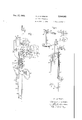
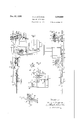
In these drawings Fig. 1 shows a perspective view; Fig. 2 a side view; and Fig. 3 an end view of an automatic arc welding apparatus in accord. ance with my invention; Fig. 4 is a diagrammatic view showing the relative arrangement oi the parts of the apparatus shown in Figs. 1, 2 and 3; Fig. 5 is a detailed view or the adjustable crank of the oscillating mechanism incorporated in the welding apparatus illustrated; and Fig.6 is a dia= grammatic illustration of a modification of my invention.
In the apparatus shown in the drawings the welding electrode l is supported in a holder 2 to which welding current is supplied through conductors 3. The electrode is held in place by means of a set screw 5 provided with a handwheel 5. The electrode holder is attached to the lower end of a feed rod 6 which is held in place relatively to the welding head l by guides it and 9. These guides also hold the feed rod 6 between feed rolls It and it of the welding head l.
In the particular welding head illustrated, feed roll [It is positively driven by feed motor l2 at a rate corresponding to the consumption of the electrode in the welding are by a control arrangement which may be such as illustrated in U. S. 5 Letters Patent No. 1,701,372, F. M. Jeits, for Are welg, granted February 5, 1929, and assigned to the same assignee as the present application. The feed roll it is positively driven by feed roll it through intermeshing gears l3 and M. m
Feed roll it is supported in a block 05 and held in engagement with the feed rod 6 by means of a spring it acting against the block it. The tension of the spring may be controlled by a set screw ll supported in the frame oi the welding head 71 15 and acting against one end of the spring it. Feed roll it may be disengaged from the feed rod 6 through the operation of a bell-crank lever l8 which when depressed forces the block it to the right against the action oi the spring it and re- 0 moves feed roll it irom driving engagement with feed rod 6.
The electrode holder and feed rod are biased to the retracted position shown in Figs. 1, 2 and 3 by a suitable means such as the spring drum 25 09 and cable til). When the lever it is depressed the-feeding engagement between the feed rolls ill and fill and the feed rod is released and the electrode holder 2 is raised to the elevated position shown in Fig. i by means of the drum and 3.0 cable arrangement illustrated. The drum is encloses a spring 2i] which tends to rotate the drum it in a counterclockwise direction (as viewed in Figs. 3 and i) to wind cable 2t upon it and thereby retract the electrode holder. It will be noted 35 that the i9 is provided with a cut out por tion or moove 22 so that it may be placed closely adjacent the feed rod 6 in order to have the cable 263 substantially in line with it. A bufier spring is located about the lower portion of the feed 40 rod 6 and acts against the abutment formed by guide 9 to cushion the impact of the electrode holder 2 against this guide when the lever it is depresmd to permit the retraction of the electrode holder. 45
D it) is supported in a bracket 24. which is attached to the welding head l. As pointed out above the feeding means 5 for carrying the electrode is guided at 9 in this bracket which constitutes a support means mounted in fixed rela- 50 tion to the welding head. This bracket also acts as a support for a block 25 to which are attached, on opposite sides of the pivot point 26, rods 2i and 28. Rod El is attached by a connecting rod 29 to an adjustable crank St. This crank is 55 rotated by a motor 3| connected thereto by a shaft 32, gears 33, shaft 34, gears 35 and 36, and a shaft 37. The construction of the adjustable crank is shown in detail in Fig. 5. The shaft 31 terminates in a keywayed block 38 to which one end of the connecting rod 29 is held by a clamp screw 39. By loosening the screw 39 the point of attachment along the length of the keyway may be varied so as to adjust the throw of the crank to various desired values. This crank acts through the connecting rod 29 and rods 21 and 28 connected by block '25 to oscillate an arm 46 attached to the lower end of the rod 28. The arm 40 is located beyond the path of movement of holder 2 and is provided with means for engaging the electrode I at a point near its arcing terminal. The mechanism just described operates to oscillate the electrode at an amplitude and rate depending upon the adjustment of the crank 30 and the speed of the motor 3|. The feed rod 6 is made of flexible material in order to permit this oscillatory movement.
Control switches are mounted on the welding head 1 at 4|. These control switches may be the start and stop buttons 24 and 25 of U. S. Letters PatentNo. 1,701,372, Jefts, February 5, 1929, above referred to. An operating member 42 for one of these control switches is adjustably supported on the upper end of the feed rod 6. In the particular arrangement employed the adjustment is such that member 42' engages the stop button after a predetermined electrode feeding movement to interrupt the welding operation.
The method of operation is as follows: An electrode I is inserted in the electrode holder 2 and clamped in place by the set screw 4 which is operated through the hand-wheel 5. The start. button is then operated to initiate the welding operation and the welding electrode l is fed toward the work to strike and maintain the welding arc during the welding operation by the welding head 1 acting through the feed rolls l0 and H on the feed rod 6. During the welding operation the electrode may be oscillated by means of the oscillating mechanism above described. When a predetermined electrode feeding movement has taken place the stop 42 on rod 6 will engage the stop button and interrupt the welding operation. The operator mayithen I by depressing the lever [8 permit the electrode holder 2 to return to its retracted position by means of the upward bias imparted to it through the drum and cable above described. The op-; erator then inserts a new electrode in the electrode holder 2 and depresses the start button to initiate another welding operation.
The electrode support may be automatically released from its driving engagement with the feed rolls of the welding head and retrieved by a retracting means after the electrode has been fed a predetermined distance and has been fused' a predetermined amount. To this end the operation of lever I8 may be made automatic by an arrangement such as illustrated in Fig. 6. In Fig. 6 the lever I8 is operated by an electromagnet 43, the energization of which is controlled by limit switches 44 and 45. These switches are operated by an arm 46 which is adjustably attached to the feed rod 6. Limit switch 44 isnormally biased toits closed position, and limit switch 45 is normally biased to an open position. Upon closure of switch 45 an operating circuit for electromagnet 43 and motor 41 is completed as follows: From terminal 48 through conductors 49 and 56 to motor 41 and coil 43, and
thence through conductor 5|, limit switch 45, conductor 52, and limit switch 44 to the other terminal of the source of supply 53. Upon the operation of lever l8 auxiliary contacts 54 complete the circuit just traced irrespective of the 5 position of the limit switch 45 and feed rolls l0 and H are withdrawn from driving engagement with feed rod 6 and feed rolls 55 and 56 are placed in driving engagement therewith. Feed motor 41 operates through feed rolls 55 and 56 to return feed rod 6 to its initial position whereby the engagement of lever 46 withlimit switch 44 its energization is interrupted. At the same time the energization of coil 43 .is also interrupted and the driving engagement of feed rolls J0 and H on the feed rod 6 reestablished for again feeding an electrode supported in the holder 2 attached to the lower end of this rod toward the work in accordance. with its consumption in the welding arc.
Preferably the speed of return of the feed rod 6 to its upper position is much greater than the speed at which it is fed downward during welding. The particular arrangement illustrated in Fig. 6 is of advantage in that the feeding move- 25 ment is not in opposition to an upward bias imparted to the electrode'holder 2 through a drum and reel or equivalent arrangement such as employed in Figs. 1, 2, 3 and 4.
It will be noted that the apparatus for feed- .ing the short length electrodes above described ofmy invention such modifications and varia- 40 tions are contemplated as fall within the scope of my invention which is set forth in the appended claims.
i What I claim as new and desire to secure by Letters Patent of the'United States is,--
1. Welding apparatus for feeding short length electrodes comprising an electrode holder, a feed. rod attached to said electrode holder, means en- .1 gaging said feed rod for feeding an electrode supported in said electrode holder toward the work to be welded, means including a motor for operating said feeding means, means for interrupting the operation of said motor, and means adjustably supported on said feed rod for operating said last-mentioned means after a prede- 55 termined electrode feeding movement.
2. Welding apparatus for feeding short length electrodes comprisingan electrode holder, a'feed 3. Welding apparatus for feeding short length electrodes comprising an electrode holder; a flexible feed rod attached to said electrode holder, means including a plurality of feed rolls engaging said feed rod for feeding said electrode holder and an electrode supported therein toward the work to be welded, means located beyond the path of movement of said holder. and engaging 75 said electrode near its arcing terminal, and
means for oscillating said electrode engaging means.
4. Welding apparatus for feeding short length electrodes comprising an electrode holder, a feed rod attached to said electrode holder, means engaging said feed rod for feeding said electrode holder toward the work to bewelded, means for releasing the engagement of said feeding means with said feed rod, and means for returning said electrode holder to its initial position upon the operation of said last mentioned means.
tion'away from the work, means engaging said feed rod for feeding said electrode holder against said bias toward the work, means for releasing the engagement of said feeding means with said feed rod, a buffer spring about said feed rod, and an abutment for said bufier spring against which it acts when said releasing means is operated for releasing said electrode holder to its retracted position.
7. Welding apparatus for feeding short length electrodes comprising a flexible feed rod, means including a plurality of feed rolls engaging said feed rod, means for guiding said feed rod between said feed rolls, an electrode holder attached to one end of said feed rod, means including a switch for controlling the welding operation, means supported on the other end of said feed rod for operating said switch after a predetermined feeding movement, means engaging near its arcing terminal an electrode supported in said holder, and means for oscillating said electrode engaging means.
8. Welding apparatus for feeding short length electrodes comprising an electrode holder, a feed rod attached to said electrode holder, means engaging said feed rod for feeding an electrode supported in.said electrode holder toward the work to be welded, means engaging said feed rod for feeding said electrode holder in a reverse direc tion, and means supported on said feed rod for controlling the operation of said last two mentioned means.
9. welding apparatus for feeding short length electrodes comprising an electrode holde a feed 10. Welding apparatus for feeding short length I electrodes comprising an electrode holder, a feed rod attached to said electrode holder, means engaging said feed rod for feeding an electrode supported in said electrode holder toward the work, means engaging said feed rod for feeding said electrode holder in a reverse direction, means'for "bination, support means mounted in fixed relaselectively operating said feeding means, and means supported on said feed rod for controlling the operation of said feeding means.
11. Welding apparatus for feeding short length electrodes comprising an electrode holder, a feed 5 rod attached to said electrode holder, means engaging said feed rod for feeding an electrode supported in said electrode holder toward and away from the work to be welded, electrical means for operating said feeding means, switching means for controlling said electrical means, and means supported on said feed rod for controlling the operation of said switching means.
12. Welding apparatus for feeding short length electrodes comprising an electrode holder, a feed rod attached to said electrode holder, means engaging said feed rod for feeding it toward the work to be welded, means engaging said feed rod for feeding it in a reverse direction, means for operating said feeding means, means for biasing one of said feeding means into engagement with the rod and the other of said feeding means out of engagement with said rod, electromagnetic means for overcoming said bias and reversing the normal feeding arrangement to retract said feed rod, means for controlling the welding operation, means supported on said feed rod for operating saidcontrolling means, limit switches spaced from one another a predetermined distance, means for connecting said limit switches to said electromagnetic means and to the means for operating said reverse feeding means, and means supported on said feed rod for operating said limit switches to control the operation of said electromagnetic means and said reverse feeding means.
13. In arc welding apparatus, in combination, support means for a welding electrode, feeding means for the support means to feed the welding electrode carried thereby as it is fused, and means for automatically retrieving the support means after the welding electrode has been fused a predetermined amount.
14. In arc welding apparatus, in combination, support means fora welding electrode, actuating means having driving connection with the support means for feeding the electrode as it is fused, and retracting means disposed to automatically function after the electrode has been fused a predetermined amount for retrieving the support means.
15. Welding electrode feeding apparatus comprising, in combination, a welding head, a motor carried by the welding head, a feed roller mounted on the welding head and having driving connection with the motor, a welding electrode support slidably mounted on the welding head and in driving engagement with the feed roller, and means for automatically releasing the electrode support from said driving engagement and retrieving it after the electrode has been fed a predetermined distance.
16. An attachment for use witha welding head for feeding short lengths of welding electrodes to perform a welding operation, comprising, in com tion to the welding head, feeding means for carrying a welding electrode, the feeding means being guided in the support means and having driving connection with the welding head, and retracting means connected to the feeding means for automatically retrieving the feeding means after having been fed a predetermined distance.
VERNI J. CHAPMAN. 7
Priority Applications (1)
| Application Number | Priority Date | Filing Date | Title |
|---|---|---|---|
| US566294A US2024965A (en) | 1931-10-01 | 1931-10-01 | Welding apparatus |
Applications Claiming Priority (1)
| Application Number | Priority Date | Filing Date | Title |
|---|---|---|---|
| US566294A US2024965A (en) | 1931-10-01 | 1931-10-01 | Welding apparatus |
Publications (1)
| Publication Number | Publication Date |
|---|---|
| US2024965A true US2024965A (en) | 1935-12-17 |
Family
ID=24262294
Family Applications (1)
| Application Number | Title | Priority Date | Filing Date |
|---|---|---|---|
| US566294A Expired - Lifetime US2024965A (en) | 1931-10-01 | 1931-10-01 | Welding apparatus |
Country Status (1)
| Country | Link |
|---|---|
| US (1) | US2024965A (en) |
Cited By (4)
| Publication number | Priority date | Publication date | Assignee | Title |
|---|---|---|---|---|
| US2588744A (en) * | 1946-11-09 | 1952-03-11 | Elox Corp | Automatic electric space-discharge material removal method and apparatus |
| US2776363A (en) * | 1950-10-24 | 1957-01-01 | Lincoln Electric Co | Arc welding process and apparatus for use therein |
| US2797352A (en) * | 1954-07-27 | 1957-06-25 | Payne Harold Spencer | Means and method for improving the starting of an electric arc |
| US3179781A (en) * | 1961-04-18 | 1965-04-20 | Union Carbide Canada Ltd | Pipe welding machine and process |
-
1931
- 1931-10-01 US US566294A patent/US2024965A/en not_active Expired - Lifetime
Cited By (4)
| Publication number | Priority date | Publication date | Assignee | Title |
|---|---|---|---|---|
| US2588744A (en) * | 1946-11-09 | 1952-03-11 | Elox Corp | Automatic electric space-discharge material removal method and apparatus |
| US2776363A (en) * | 1950-10-24 | 1957-01-01 | Lincoln Electric Co | Arc welding process and apparatus for use therein |
| US2797352A (en) * | 1954-07-27 | 1957-06-25 | Payne Harold Spencer | Means and method for improving the starting of an electric arc |
| US3179781A (en) * | 1961-04-18 | 1965-04-20 | Union Carbide Canada Ltd | Pipe welding machine and process |
Similar Documents
| Publication | Publication Date | Title |
|---|---|---|
| US2360160A (en) | Gas-arc welding apparatus | |
| US3141085A (en) | Work-in-circuit consumable electrode arc welding | |
| US2444834A (en) | High-speed arc welding | |
| US2024965A (en) | Welding apparatus | |
| US2731536A (en) | Welding wire positioning | |
| US2571684A (en) | Gas shielded arc welding torch | |
| US3312810A (en) | Automatic stud feeder | |
| US2723331A (en) | Arc welding apparatus | |
| US3239120A (en) | Semi-automatic wire feeder having interchangeable gears | |
| US2778099A (en) | Method of welding and apparatus therefor | |
| US20020011474A1 (en) | Welding machine manipulated by automated equipment | |
| JPH06344142A (en) | Tube-inside peripheral surface build-up welding equipment and welding torch | |
| JPS563146A (en) | Wire cut electric discharge machine | |
| US2329904A (en) | Apparatus for welding | |
| RU2470754C2 (en) | Device and method for making welding electrode tip | |
| GB2060721A (en) | Apparatus for applying paraffin to yarn | |
| GB1042873A (en) | Improvements in or relating to welding machines | |
| US1638024A (en) | Arc-welding machine | |
| US4437600A (en) | Continuous wire feed arrangement for stapling apparatus | |
| CN109641320B (en) | Device and method for laser welding with the aid of additional material and control program | |
| US3107291A (en) | Electrode feed apparatus | |
| US2909646A (en) | Electrode feed apparatus | |
| US2364826A (en) | Apparatus for arc welding | |
| US1932263A (en) | Arc welding | |
| US3207885A (en) | Nozzle adjustment device for submerged-arc automatic welding machines |