US2024941A - Retreading vulcanizer for tires - Google Patents
Retreading vulcanizer for tires Download PDFInfo
- Publication number
- US2024941A US2024941A US702368A US70236833A US2024941A US 2024941 A US2024941 A US 2024941A US 702368 A US702368 A US 702368A US 70236833 A US70236833 A US 70236833A US 2024941 A US2024941 A US 2024941A
- Authority
- US
- United States
- Prior art keywords
- rim
- mold
- tire casing
- vulcanizer
- tire
- Prior art date
- Legal status (The legal status is an assumption and is not a legal conclusion. Google has not performed a legal analysis and makes no representation as to the accuracy of the status listed.)
- Expired - Lifetime
Links
Images
Classifications
-
- B—PERFORMING OPERATIONS; TRANSPORTING
- B29—WORKING OF PLASTICS; WORKING OF SUBSTANCES IN A PLASTIC STATE IN GENERAL
- B29D—PRODUCING PARTICULAR ARTICLES FROM PLASTICS OR FROM SUBSTANCES IN A PLASTIC STATE
- B29D30/00—Producing pneumatic or solid tyres or parts thereof
- B29D30/06—Pneumatic tyres or parts thereof (e.g. produced by casting, moulding, compression moulding, injection moulding, centrifugal casting)
- B29D30/52—Unvulcanised treads, e.g. on used tyres; Retreading
- B29D30/54—Retreading
Definitions
- This invention relates to certain new and useful improvements in retreading vulcanizers for tires.
- An important object of the invention resides 5 in the provision of a retreading vulcanizer for tires wherein the entire tire casing is retreaded in one single operation as distinguished from prior methods and devices that accomplish the retreading in a series of distinct operations.
- a further object of the invention is to provide a retreading vulcanizer of the foregoing character embodying an adjustable element permitting the vulcanization and retreading of tire casings of different widths with a standard size apparatus.
- a further and important object of the invention is to present only the tread portion of the tire casing to the form or mold of the retreading vulcanizer with the side beads of the tire casing exposed to atmosphere to prevent material application of heat'to the beaded portions of the tire casing to obviate any damage or injury that may occur to said bead portions of the tire casing during a retreading operation.
- the invention has for a further object to provide a quickly collapsible rim for the support of an inner tube within the tire casing being retreaded that permits ready access to the tube in the event of necessity for repair or otherwise during a vulcanization operation without removing the tire casing from the vulcanizer.
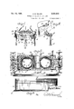
- Figure 1 is a fragmentary perspective View of a retreading vulcanizer for tires constructed in accordance with the present invention showing the two sections of the vulcanizer mold clamped together;
- Figure 2 is a fragmentary perspective view 5 showing one of the clamping bolts between the two mold sections disengaged from the upper section and retainingly supported on thelower mold section;
- Figure 3 is a cross-sectional View through the 10 assembled mold section, partly broken away, and showing the valve controlled communicating openings between the steam jacketed mold sections and the adjustable screw ring having threaded engagement with the tire casing sup- 15 porting rim and bead of the tire casing;
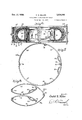
- Figure 4 is a side elevational view of the adjustable screw ring
- Figure 5 is a fragmentary side elevational view of the tire casing supporting rim
- Figure 6 kis a cross-sectional view of the vul-- canizer equipped with a collapsible tire casing supporting rim and illustrating the beaded side 4 portions of the tire casing disposed outwardly of the mold section to be unaffected by heat from 25 the vulcanizer;
- Figure '7 is a side elevational view of the collapsible rim removed from the vulcanizer.
- Figure 8 is a side elevational view of the rim in collapsed condition.
- a retreading vulcanizer for tire casngs there is illustrated a retreading vulcanizer for tire casngs, it being vunderstood however that other articles may well be vulcanized within the apparatus 35 with slight modifications, the vulcanizer comprising mold sections IQ and II, the lower mold section being illustrated as mounted upon supporting legs IZ while the mold section I Il has hoist chains I3 attached thereto to facilitate manipu- 40 lation and placement ofV the mold sections in mating relationship.
- each apertured lug I5 carries an 55 by means of the outwardly directed loop frame I9 for the support of the tie bolt on the mold section I I as shown in Figure 2.
- Each of the mold sections I0 and II is of ring formation and has a side wall 2B and an annular wall 2l projecting at right angles from its outer edge, the two walls being connected by a curved wall 22 so that when the two mold sections I0 and I I are assembled as shown in Figure 3, the curved walls 22 form aV continuously curved tire casing tread engaging portion.
- the faces of thev curved walls 22 of the mold sections engaged by the thread of the tire casing are suitably configurated to produce the desired design upon the tire casing tread, or said faces may have design plates suitably secured thereto.
- each mold section provides a steam chamber 24 in each mold section.
- a diametrically oposite hollow boss 25 projects outwardly of each mold section for abutting engagemement when the mold sections are assembled as shown in Figure 3, the hollow bosses communicating with the steam chambers 24, steam communication between the two chambers Vand hollow bosses being afforded by the-,registering Valve openings 26 in adjacent walls of thehollow bosses 25, said valve openings being controlledV by the manually operable valves 2-1 supported in the outer walls of the hollow bosses 25.
- Steam supply openings 28 are formed in the wall 20 of the mold section II, steam communication between the chambers 24' of the two mold sections being controlled by the valves 21. A steam tight connection is established between the hollow bosses 25 openings 26.
- An annular adjustable rim 30 is provided for the support of a tire casing andthe inner edges of the ring walls are spaced outwardly of the adjustable rim 30, one side edge of the rim 30 carries an outwardly directed annular bead 3I while the other side edge of the rim is threaded as at 32 for the receptionof an Vadjusting ring 33 that is manipulated by means of the handles 34 diametrically carried by the ring.
- a tire casing C is supported in the-mating mold sections ID and II and Vit will be'observed that the tire 'beads B project outwardlybeyondthe adjacent'edges' ofthe side walls 2D of the mold sections and to a position to be removed from the heat zone of the vulcanizer.
- TheI tire casing C is supported upon the rim 30 with one bead B en- ⁇ gaged with the rim bead 3
- tire casings of various widths may be mounted inthe vulcanizer for presenting the tread portionv of the tire casing C to the curved walls 22-'of the-moldY sections.
- the mold sections I and II Vassembled afs-illustrated in Figs. 1 and 3 steam'is supplied to the steam chamber 24 through the steam inlet 28 and ows by way of the hollow bosses into the steam chamber 24 of the other mold section, heat radiating to the curved walls 22 for the vulcanization of'retreaded'portion of the tire casingC.
- a collapsible rim is substituted for the rigid rim 3
- a 30' handle 39 is carried by the rim sections 35 adjacent the locking connection to facilitate collapsing of the rim, it beingfunderstood that the rim 32a becomes quite highly heated during vulcanizing operation. 35;
- the rim 32a is disposed between the side walls of the tire casing C with the tire beads B exposed to atmosphere and removed from the heat zone of the vulcanizer.
- inner tube T is interposed between the rim and 40 inner wall of the tire casing and is used in lieu of the usual expensive air bags or fan bags.
- the collapsible ring 32a is easily removed from the tire casing to permit the substitution of a new tube.
- a pair of mold sections adapted to be clamped together and constructed and arranged for the support of a tire casing with the tire beads located exteriorly of the mold sections, a steam chamber in each mold section, means forming v communication between theV steam chamber, means for supplying steam to one of the chambers, an annular rim for the support of the tire casing and a tire engaging ring having threaded engagement with the rim with the rim detachable from the mold without disturbing the mold sections.
- a pair of mold sections adapted to be clamped together and constructed and arranged for the support of a tire casing with the tire beads located exteriorly of the mold sections, a steam chamber in each mold section, means forming communication between the steam chambers, a
- each mold section for shutting u off communication between the mold sections whereby the sections may be separated with steam confined in the chamber thereof, and means for supplying steam to one of the chambers, an annular rim for the support of the tire casing and a tire engaging ring having threaded engagement with the rim with the rim detachable from the mold without disturbing the mold sections.
- a pair of mold sections adapted to be clamped together and constructed and arranged for the support of a tire casing with the tire beads located exteriorly of the mold sections, a steam chamber in each mold section, means forming communication between the steam chamber, means for supplying steam to one of the chambers, an annular rim for the support of the tire casing and a tire engaging ring having threaded engagement with the rim with the rim detachable from the mold without disturbing the mold sections, and an iniiated inner tube interposed between the tire casing and rim.
Landscapes
- Engineering & Computer Science (AREA)
- Mechanical Engineering (AREA)
- Moulds For Moulding Plastics Or The Like (AREA)
- Heating, Cooling, Or Curing Plastics Or The Like In General (AREA)
Description
Dec. 17, 1935. c. E. MILLER 2,024,941
RETREADING VULCANIZER FQR TIRES Filed Deo. 14, l1953 2 Sheets-Sheet l 2 fA"\.-7/- w W rm Wm ,W www www N, A m, -Wmmmm o w1 m riff/falla' MLK Dec. 17, 1935. c. E. MILLER RETREADING VULCANIZER FOR TIRES z'sheets-sheet 2 Filed DGO. 1.4, 1935 MW Mille?.
Charle E.
www5,
Patented Dec. 17, 1935 UNITED STATES PATENT OFFICE 3 Claims.
This invention relates to certain new and useful improvements in retreading vulcanizers for tires. An important object of the invention resides 5 in the provision of a retreading vulcanizer for tires wherein the entire tire casing is retreaded in one single operation as distinguished from prior methods and devices that accomplish the retreading in a series of distinct operations.
A further object of the invention is to provide a retreading vulcanizer of the foregoing character embodying an adjustable element permitting the vulcanization and retreading of tire casings of different widths with a standard size apparatus.
A further and important object of the invention is to present only the tread portion of the tire casing to the form or mold of the retreading vulcanizer with the side beads of the tire casing exposed to atmosphere to prevent material application of heat'to the beaded portions of the tire casing to obviate any damage or injury that may occur to said bead portions of the tire casing during a retreading operation.
It is a further obj ect of the invention to provide a retreading vulcanizer having mating steam jacketed mold sections to be separated for placement and removal of the tire casing from the vulcanizer with steam supply means for one of 30' the mold sections that in turn is in steam communication with the other mold section with manually cperablevalves for shutting off steam communication between the two mold sections Yso that when the mold sections are separated for the purpose of removing a retreaded tire casing, or for other purposes, steam is confined in the separated mold sections to prevent the chilling of said'sections and retaining them preheated to a considerable degree for a subsequent retreading operation.
The invention has for a further object to provide a quickly collapsible rim for the support of an inner tube within the tire casing being retreaded that permits ready access to the tube in the event of necessity for repair or otherwise during a vulcanization operation without removing the tire casing from the vulcanizer.
With the above and other objects in view that will become apparent as the nature of the invention is better understood, the same consists in the novel form, combination and arrangement of parts hereinafter more fully described, shown in the accompanying drawings and claimed.
Y In the drawings:.
Figure 1 is a fragmentary perspective View of a retreading vulcanizer for tires constructed in accordance with the present invention showing the two sections of the vulcanizer mold clamped together;
Figure 2 is a fragmentary perspective view 5 showing one of the clamping bolts between the two mold sections disengaged from the upper section and retainingly supported on thelower mold section;
Figure 3 is a cross-sectional View through the 10 assembled mold section, partly broken away, and showing the valve controlled communicating openings between the steam jacketed mold sections and the adjustable screw ring having threaded engagement with the tire casing sup- 15 porting rim and bead of the tire casing;
Figure 4 is a side elevational view of the adjustable screw ring;-
Figure 5 is a fragmentary side elevational view of the tire casing supporting rim;
' Figure 6 kis a cross-sectional view of the vul-- canizer equipped with a collapsible tire casing supporting rim and illustrating the beaded side 4 portions of the tire casing disposed outwardly of the mold section to be unaffected by heat from 25 the vulcanizer;
Figure '7 is a side elevational view of the collapsible rim removed from the vulcanizer; and
Figure 8 is a side elevational view of the rim in collapsed condition.
Referring more in detail to the accompanying drawings and particularly Figs. 1 to 5, there is illustrated a retreading vulcanizer for tire casngs, it being vunderstood however that other articles may well be vulcanized within the apparatus 35 with slight modifications, the vulcanizer comprising mold sections IQ and II, the lower mold section being illustrated as mounted upon supporting legs IZ while the mold section I Il has hoist chains I3 attached thereto to facilitate manipu- 40 lation and placement ofV the mold sections in mating relationship.
The tie bolt connection is provided between the two sections I!! and I I of the vulcanizer for maintaining intimate contact therebetween andv as 45 shown in Figs. 1 and 2, the mold sections II) and II carry a series of peripherally projecting apertured lugs I4 and I5 respectively for cooperation with each other by means of tie bolts I6 having their lower headed ends I'I engaged with the lugs 50 I5 with the upper ends of the tie bolts I6 projecting through the apertured lugs I 4 and receiving a washer and nut combination I8. To prevent loss of the tie bolts I6 when the mold sections I0 and I I are separated, each apertured lug I5 carries an 55 by means of the outwardly directed loop frame I9 for the support of the tie bolt on the mold section I I as shown in Figure 2.
Each of the mold sections I0 and II is of ring formation and has a side wall 2B and an annular wall 2l projecting at right angles from its outer edge, the two walls being connected by a curved wall 22 so that when the two mold sections I0 and I I are assembled as shown in Figure 3, the curved walls 22 form aV continuously curved tire casing tread engaging portion. The faces of thev curved walls 22 of the mold sections engaged by the thread of the tire casing are suitably configurated to produce the desired design upon the tire casing tread, or said faces may have design plates suitably secured thereto. As shown in Figures 3 and 4, the free ends of the annular walls 2| and adjacent ends oi the curved Walls 22 are connected by ashort wall 23 that abuttingly engage when the mold sections I andV II are assembled. The wall arrangement of each mold section provides a steam chamber 24 in each mold section.
A diametrically oposite hollow boss 25: projects outwardly of each mold section for abutting engagemement when the mold sections are assembled as shown in Figure 3, the hollow bosses communicating with the steam chambers 24, steam communication between the two chambers Vand hollow bosses being afforded by the-,registering Valve openings 26 in adjacent walls of thehollow bosses 25, said valve openings being controlledV by the manually operable valves 2-1 supported in the outer walls of the hollow bosses 25. Steam supply openings 28 are formed in the wall 20 of the mold section II, steam communication between the chambers 24' of the two mold sections being controlled by the valves 21. A steam tight connection is established between the hollow bosses 25 openings 26.
An annular adjustable rim 30 is provided for the support of a tire casing andthe inner edges of the ring walls are spaced outwardly of the adjustable rim 30, one side edge of the rim 30 carries an outwardly directed annular bead 3I while the other side edge of the rim is threaded as at 32 for the receptionof an Vadjusting ring 33 that is manipulated by means of the handles 34 diametrically carried by the ring.
As shown inrFigure 3 of the' drawings, a tire casing C is supported in the-mating mold sections ID and II and Vit will be'observed that the tire 'beads B project outwardlybeyondthe adjacent'edges' ofthe side walls 2D of the mold sections and to a position to be removed from the heat zone of the vulcanizer. TheI tire casing C is supported upon the rim 30 with one bead B en-` gaged with the rim bead 3| while the other tire casing bead B is engaged by the screw ring 33'. It will be understood that byadjusting the screw ring V33, tire casings of various widths may be mounted inthe vulcanizer for presenting the tread portionv of the tire casing C to the curved walls 22-'of the-moldY sections. With the mold sections I and II Vassembled afs-illustrated in Figs. 1 and 3, steam'is supplied to the steam chamber 24 through the steam inlet 28 and ows by way of the hollow bosses into the steam chamber 24 of the other mold section, heat radiating to the curved walls 22 for the vulcanization of'retreaded'portion of the tire casingC. `The rubber strips forming the retread are placed in Vthe mold to be engaged by the tire casing and by a single operation, complete vulcanization isl accomplished. When it is desiredrrto remove the regaskets`29 between the valve Y ployed within the tire casingA during vulcaniza- 10 tion and is retained in position by means of the rim for expansion engagement with the inner walls of the tread portion of the tire casing. In event of injury to the inner tube during vulcanization, the rim 30 may be removed from the mold 15 sections of the vulcanizer without disturbing' the tire casing, a new air bag or inner tube substituted and the rim replaced. Also, it is possible to insert a spacing ring between the two mold sections I0 and I I including the hollow bosses 25 20 so that tire casings of greatly increased width may be vulcanized in the apparatus.
In the form of invention shown in Figs. 6 to 8,
a collapsible rim is substituted for the rigid rim 3|] shown in Figure 5, the rim 32a being formed 251 of sections 35 that are hinged together as at 36, a pair of adjacent sections 35 being unhinged and each carrying at its free end an apertured lug 31 to receive a locking pin for holding the several rim sections in expanded circular formation. A 30' handle 39 is carried by the rim sections 35 adjacent the locking connection to facilitate collapsing of the rim, it beingfunderstood that the rim 32a becomes quite highly heated during vulcanizing operation. 35;
As shown in Figure 6, the rim 32a is disposed between the side walls of the tire casing C with the tire beads B exposed to atmosphere and removed from the heat zone of the vulcanizer. The
inner tube T is interposed between the rim and 40 inner wall of the tire casing and is used in lieu of the usual expensive air bags or fan bags. In the event of injury to the inner tube T, the collapsible ring 32a is easily removed from the tire casing to permit the substitution of a new tube.
From the above detailed description of the invention, it is believed that the constructionand operation thereof will at once be apparent, and while there are herein shown and described the preferred embodiments of the invention, it is nevertheless to be understood that` minor changes may be made therein without departing from the spirit and scope of the invention as claimed.
I claimzl. In a retreading vulcanizer ofthe character described, a pair of mold sections adapted to be clamped together and constructed and arranged for the support of a tire casing with the tire beads located exteriorly of the mold sections, a steam chamber in each mold section, means forming v communication between theV steam chamber, means for supplying steam to one of the chambers, an annular rim for the support of the tire casing and a tire engaging ring having threaded engagement with the rim with the rim detachable from the mold without disturbing the mold sections.
2. In a retreading vulcanizer of the character described, a pair of mold sections adapted to be clamped together and constructed and arranged for the support of a tire casing with the tire beads located exteriorly of the mold sections, a steam chamber in each mold section, means forming communication between the steam chambers, a
valve carried by each mold section for shutting u off communication between the mold sections whereby the sections may be separated with steam confined in the chamber thereof, and means for supplying steam to one of the chambers, an annular rim for the support of the tire casing and a tire engaging ring having threaded engagement with the rim with the rim detachable from the mold without disturbing the mold sections.
3. In a retreading vulcanizer of the character described, a pair of mold sections adapted to be clamped together and constructed and arranged for the support of a tire casing with the tire beads located exteriorly of the mold sections, a steam chamber in each mold section, means forming communication between the steam chamber, means for supplying steam to one of the chambers, an annular rim for the support of the tire casing and a tire engaging ring having threaded engagement with the rim with the rim detachable from the mold without disturbing the mold sections, and an iniiated inner tube interposed between the tire casing and rim.
CHARLES E. LHLLER.
Priority Applications (1)
| Application Number | Priority Date | Filing Date | Title |
|---|---|---|---|
| US702368A US2024941A (en) | 1933-12-14 | 1933-12-14 | Retreading vulcanizer for tires |
Applications Claiming Priority (1)
| Application Number | Priority Date | Filing Date | Title |
|---|---|---|---|
| US702368A US2024941A (en) | 1933-12-14 | 1933-12-14 | Retreading vulcanizer for tires |
Publications (1)
| Publication Number | Publication Date |
|---|---|
| US2024941A true US2024941A (en) | 1935-12-17 |
Family
ID=24820943
Family Applications (1)
| Application Number | Title | Priority Date | Filing Date |
|---|---|---|---|
| US702368A Expired - Lifetime US2024941A (en) | 1933-12-14 | 1933-12-14 | Retreading vulcanizer for tires |
Country Status (1)
| Country | Link |
|---|---|
| US (1) | US2024941A (en) |
Cited By (3)
| Publication number | Priority date | Publication date | Assignee | Title |
|---|---|---|---|---|
| US2418584A (en) * | 1946-06-07 | 1947-04-08 | Hawkinson Paul E Co | Tire retreading equipment |
| DE1063365B (en) * | 1952-04-15 | 1959-08-13 | Super Mold Corp | Bracket for pneumatic tires |
| US2980950A (en) * | 1958-08-18 | 1961-04-25 | James A Smyser | Tire chuck |
-
1933
- 1933-12-14 US US702368A patent/US2024941A/en not_active Expired - Lifetime
Cited By (3)
| Publication number | Priority date | Publication date | Assignee | Title |
|---|---|---|---|---|
| US2418584A (en) * | 1946-06-07 | 1947-04-08 | Hawkinson Paul E Co | Tire retreading equipment |
| DE1063365B (en) * | 1952-04-15 | 1959-08-13 | Super Mold Corp | Bracket for pneumatic tires |
| US2980950A (en) * | 1958-08-18 | 1961-04-25 | James A Smyser | Tire chuck |
Similar Documents
| Publication | Publication Date | Title |
|---|---|---|
| US2066265A (en) | Method of curing tires | |
| US2626885A (en) | Method of making washing machine liners | |
| US2571258A (en) | Pneumatic tire shaping and vulcanizing apparatus | |
| US1707014A (en) | Tire and process of making same | |
| US2155906A (en) | Vulcanizer | |
| US1996971A (en) | Apparatus for vulcaniziing tires | |
| US2024941A (en) | Retreading vulcanizer for tires | |
| US3871941A (en) | Apparatus used in bonding a precured tread on a tire casing | |
| US1923736A (en) | Vulcanizing device | |
| US3002228A (en) | Method of vulcanizing nylon tires | |
| US2354446A (en) | Method of molding and vulcanizing hollow articles | |
| US1785659A (en) | Tire-building machine | |
| US2030861A (en) | Tire retreading mold | |
| US2034618A (en) | Tire retreading apparatus | |
| US3162898A (en) | Apparatus for use in retreading tires | |
| US2606342A (en) | Vulcanizing apparatus for retreading tires | |
| US2020023A (en) | Tire retreading and remolding apparatus | |
| US2659104A (en) | Tire locating ring assembly for retreading molds | |
| US2320778A (en) | Tire vulcanizing apparatus | |
| US2327639A (en) | Convertible tire vulcanizer | |
| US2574171A (en) | Tire side wall mold | |
| US1928404A (en) | Method and apparatus for retreading tires | |
| US1834899A (en) | Tire retread vulcanizer | |
| US2100478A (en) | Full-circle tire retreading vulcanizer | |
| USRE19895E (en) | Method and machine for building |