US2024928A - Screen stile - Google Patents
Screen stile Download PDFInfo
- Publication number
- US2024928A US2024928A US699943A US69994333A US2024928A US 2024928 A US2024928 A US 2024928A US 699943 A US699943 A US 699943A US 69994333 A US69994333 A US 69994333A US 2024928 A US2024928 A US 2024928A
- Authority
- US
- United States
- Prior art keywords
- screen
- stile
- cloth
- recess
- flange
- Prior art date
- Legal status (The legal status is an assumption and is not a legal conclusion. Google has not performed a legal analysis and makes no representation as to the accuracy of the status listed.)
- Expired - Lifetime
Links
Images
Classifications
-
- E—FIXED CONSTRUCTIONS
- E06—DOORS, WINDOWS, SHUTTERS, OR ROLLER BLINDS IN GENERAL; LADDERS
- E06B—FIXED OR MOVABLE CLOSURES FOR OPENINGS IN BUILDINGS, VEHICLES, FENCES OR LIKE ENCLOSURES IN GENERAL, e.g. DOORS, WINDOWS, BLINDS, GATES
- E06B9/00—Screening or protective devices for wall or similar openings, with or without operating or securing mechanisms; Closures of similar construction
- E06B9/52—Devices affording protection against insects, e.g. fly screens; Mesh windows for other purposes
Definitions
- the present invention is designed to improve metal screen frames, or stiles.
- Such stiles as at present commonly made are provided with a locking groove into which the edge of the screen is placed and it is locked in the groove by a strip forming a locking key extending the length of the groove.
- My structure permits also of the ready removal and. replacement of screens, permits of such replacement without the aid of skilled labor, permits the final finish on the frame before the introduction of the cloth and assures a more rigid structure with less weight.
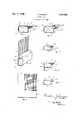
- Fig. 1 shows a cross section through the stile with the screen locked in place thereon.
- Fig. 2 a section with the stile in its initial position.
- Fig. 4 a corner of the screen fabricated with stiles according to the invention.
- Fig. 5 an alternative form involving a snap lock for the screen.
- Fig. 6 an alternative form having a guide loop on the screen stile.
- Fig. '7 an alternative construction showing a modification of the screen securing means along the stile edge.
- a stile 2 is preferably of tubular form having a side wall 3, an outer wall 4, and a side wall 5.
- the channel is formed in extension of the wall 3, this channel having sides 6 and I.
- An inner wall 8 extends from the side wall 5 and is provided with an out-turned portion In which engages and overlaps the channel side I.
- the channel side and extension H) are secured together, preferably by spot welding at intervals H. Other means of securing these parts together may be used. The purpose of securing these parts together is to complete the tubular section of the stile and thus strengthen and stiffen it.
- a metal flange i2 projects from the extension iii over the channel having the side walls 6 and I. This flange has a folded edge I3 over which the screen cloth is drawn and tensioned.
- the screen cloth is drawn over the folded edge i3 and a fold of the cloth is forced under the flange through an opening I4 into the recess.
- This may be readily accomplished by any common implement, such as a screw driver. is then bent downwardly into the recess and this may be readily accomplished by placing a small block on the screen above the edge and hammering it down into place.
- the screen 15 is given a slight added and final tension.
- this complete tubular form gives more strength with a small amount of weight.
- the angles formed by the sides 6 and I tend to strengthen the structure.
- the extension Ill with its return flange very materially strengthens the frame, particularly as against the strain, or pull'of the screen. At the same time this extension makes an attractive finish along the union of the cloth and the stiles on the inside of the screen.
- the outside of the structure also makes an attractive finish as the only seam or crack in the surface is that into which the screen cloth extends.
- the stile is of such form that it may be fabricated in long lengths and by continuous operations. In fabricating a complete screen frame the proper lengths of stiles are cut with mitered ends and these ends are preferably secured together by butt welding. For all practical purposes this gives a desirable finish and sufiicient strength.
- the tubular form readily lends itself to re-enforcements if that is desired.
- I preferably round at it the rear corners of the stiles while leaving the edge itself flat so that the stile has practically a universal application and may be used in ordinary guide grooves, or may be hinged on a pin center, as I! (see Fig. 1).
- a side 6a. of the channel has a slight over-hang at the face of the stile and a return fold 13a. of the flange is so shaped and proportioned as to snap into position below the overhanging wall of the part 6a and thus secure the screen cloth.
- the rear wall 16a of the stile has a guide loop l8 formed in extension thereof so as to adapt the screen for a guide slot, if desired.
- a flange 12a is formed on the side wall 1a of the channel instead of on the extension H] as in Fig. 1.
- a screen stile comprising screen supporting walls having a screen cloth receiving recess and an outward wall extension comprising a return bend over which the screen cloth may be drawn with its edge within the recess securing a screen cloth in the recess.
- a screen stile comprising screen supporting walls and means permanently connected to said walls securing a screen cloth thereto comprising a bendable flange extending initially out) of the plane of the cloth and having an edge over which the cloth may be folded, said flange tensioning the screen cloth as it is bent to a final position to secure the cloth.
- a screen stile comprising screen supporting walls having a screen cloth receiving recess and means permanently connected to said walls securing a screen cloth in the recess, said means extending from one Wall of the recess and having a snap engagement with the opposite wall of the recess to secure the screen cloth in the recess.
- a screen securing structure comprising a trough-shaped member receiving a screen cloth and a cloth securing flange extending from one wall of the member under the cloth and bendable into the member.
- a screen securing structure comprising a trough-shaped member receiving a screen cloth and a cloth securing flange extending from a wall of the member under the cloth into the member, said flange having a folded edge for receiving a screen cloth fold.
- a screen securing structure comprising a trough-shaped member receiving a screen cloth and a cloth securing flange extending from a wall of the member under the cloth into the member, the, flange being adapted to enter a screen cloth fold with its edge at the fold bend.
- a screen securing structure comprising a trough-shaped member receiving a screen cloth and a cloth'securing flange extending from a wall'of the member under the cloth into the member, the flange being adapted to enter a screen cloth fold with its edge at the fold bend and bendable into locking position into the member.
- a screen stile comprising screen supporting walls permanently tubular with a complete annulus in cross section and means permanently connected to said walls securing a screen cloth thereto.
- a screen stile comprising screen supporting walls of tubular cross section and a wall extension from the tubular section having a screenreceiving recess and having a flange for securing a screen cloth in the recess.
- a screen stile comprising screen supporting walls of tubular cross section and a wall extension from the tubular section having a screen-receiving recess and having a flange bendable into locking position in the recess to secure a screen cloth.
- a screen stile comprising screen supporting walls tubular in cross section, the joining portions of said walls being permanently secured together, and a wall extension bendable to secure a screen cloth to the stile.
- a screen stile comprising screen supporting walls tubular in cross section, the joining edges being secured together and having a screen-receiving recess and a wall extension bendable into the recess for securing a screen cloth.
- a screen stile comprising screen supporting walls of U form in cross section, an outward extension from one of the sides forming a trough-shaped member, an extension from the other side of the U section engaging and secured to one Wall of the member, and a flange extending over the member and bendable into the member to secure a screen cloth therein.
- a screen stile comprising screen supporting walls of U form in cross section, an outward extension from one of the sides forming a trough-shaped member, an extension from the other side of the U section engaging and secured to one wall of the member, and a flange extending over the member and bendable into the member to secure a screen cloth therein, said flange having a folded edge.
- a screen stile comprising screen supporting walls of U form in cross section, an exten- 'sion from one side forming a recess with an overhanging portion, an extension from the opposite side secured to the first-named extension, and a flange having an edge adapted to snap under said overhanging portion to secure a screen cloth between the flange and extension.
- a screen stile comprising screen supporting walls having a screen cloth receiving recess extending inwardly from the face of the stile; a screen having its edge folded into the recess; and means permanently connected with said walls locking the screen cloth fold in the recess.
Landscapes
- Engineering & Computer Science (AREA)
- Structural Engineering (AREA)
- Life Sciences & Earth Sciences (AREA)
- Insects & Arthropods (AREA)
- Pest Control & Pesticides (AREA)
- Architecture (AREA)
- Civil Engineering (AREA)
- Blinds (AREA)
Description
Dec. 17, 1935. JOHNSON 2,024,928
SCREEN 'STILE Filed Nov. 27, 1953 V Hy. 7
A TTORNEYSJ Patented Dec. 17, 1935 UNITED STATES SCREEN STILE Theodore Johnson, Erie, Pa.., assignor to Johnson Metal Products Company, Erie, Pa., a corporation of Pennsylvania Application November 2'2, 1933, Serial No. 699,943
17 Claims.
The present invention is designed to improve metal screen frames, or stiles. Such stiles as at present commonly made are provided with a locking groove into which the edge of the screen is placed and it is locked in the groove by a strip forming a locking key extending the length of the groove. In the present invention I form the stile in one piece, preferably an integral piece of sheet metal, and provide a means in this piece by which the screen may be securely locked in the stile. In this way I am enabled to form a very much cheaper, more efiicient and sightly structure than in the structures utilizing separate keys. Further I am enabled to utilize the securing means in giving to the screen cloth a final tension. My structure permits also of the ready removal and. replacement of screens, permits of such replacement without the aid of skilled labor, permits the final finish on the frame before the introduction of the cloth and assures a more rigid structure with less weight. Features and details of the invention will appear from the specification and claims.
A preferred embodiment of the invention is illustrated in the accompanying drawing as follows:
Fig. 1 shows a cross section through the stile with the screen locked in place thereon.
Fig. 2 a section with the stile in its initial position.
Fig. 3 a perspective view of a fragment of the stile.
Fig. 4 a corner of the screen fabricated with stiles according to the invention.
Fig. 5 an alternative form involving a snap lock for the screen. I
Fig. 6 an alternative form having a guide loop on the screen stile.
Fig. '7 an alternative construction showing a modification of the screen securing means along the stile edge.
1 marks the screen. A stile 2 is preferably of tubular form having a side wall 3, an outer wall 4, and a side wall 5.
The channel is formed in extension of the wall 3, this channel having sides 6 and I. An inner wall 8 extends from the side wall 5 and is provided with an out-turned portion In which engages and overlaps the channel side I. The channel side and extension H) are secured together, preferably by spot welding at intervals H. Other means of securing these parts together may be used. The purpose of securing these parts together is to complete the tubular section of the stile and thus strengthen and stiffen it. A metal flange i2 projects from the extension iii over the channel having the side walls 6 and I. This flange has a folded edge I3 over which the screen cloth is drawn and tensioned. In assembling the screen, the screen cloth is drawn over the folded edge i3 and a fold of the cloth is forced under the flange through an opening I4 into the recess. This may be readily accomplished by any common implement, such as a screw driver. is then bent downwardly into the recess and this may be readily accomplished by placing a small block on the screen above the edge and hammering it down into place. It will be noted that as The flange 10 the flange is bent down into place the screen 15 is given a slight added and final tension. When the flange is forced to its final position in the recess the screen, by reason of its fold over the edge and its fold within the recess, is securely locked in place. i
With this construction the screen may be very readily replaced by prying open the flange and the replacement assembly is accomplished in the same manner as just described.
It will be noted that this complete tubular form gives more strength with a small amount of weight. The angles formed by the sides 6 and I tend to strengthen the structure. The extension Ill with its return flange very materially strengthens the frame, particularly as against the strain, or pull'of the screen. At the same time this extension makes an attractive finish along the union of the cloth and the stiles on the inside of the screen. The outside of the structure also makes an attractive finish as the only seam or crack in the surface is that into which the screen cloth extends.
The stile is of such form that it may be fabricated in long lengths and by continuous operations. In fabricating a complete screen frame the proper lengths of stiles are cut with mitered ends and these ends are preferably secured together by butt welding. For all practical purposes this gives a desirable finish and sufiicient strength. The tubular form, however, readily lends itself to re-enforcements if that is desired.
I preferably round at it the rear corners of the stiles while leaving the edge itself flat so that the stile has practically a universal application and may be used in ordinary guide grooves, or may be hinged on a pin center, as I! (see Fig. 1).
In the form shown in Fig. 5, a side 6a. of the channel has a slight over-hang at the face of the stile and a return fold 13a. of the flange is so shaped and proportioned as to snap into position below the overhanging wall of the part 6a and thus secure the screen cloth.
In the modification shown in Fig. 6, the rear wall 16a of the stile has a guide loop l8 formed in extension thereof so as to adapt the screen for a guide slot, if desired.
In the modification shown in Fig. 7, a flange 12a is formed on the side wall 1a of the channel instead of on the extension H] as in Fig. 1.
What I claim as new is:-
1. A screen stile comprising screen supporting walls having a screen cloth receiving recess and an outward wall extension comprising a return bend over which the screen cloth may be drawn with its edge within the recess securing a screen cloth in the recess.
2. A screen stile comprising screen supporting walls and means permanently connected to said walls securing a screen cloth thereto comprising a bendable flange extending initially out) of the plane of the cloth and having an edge over which the cloth may be folded, said flange tensioning the screen cloth as it is bent to a final position to secure the cloth.
7 '3.'A screen stile comprising screen supporting walls having a screen cloth receiving recess and means permanently connected to said Walls securing a screen cloth in the recess, said means extending from one wall of the recess and being bendable into position in the recess to secure the screen cloth. I
4. A screen stile comprising screen supporting walls having a screen cloth receiving recess and means permanently connected to said walls securing a screen cloth in the recess, said means extending from one Wall of the recess and having a snap engagement with the opposite wall of the recess to secure the screen cloth in the recess.
'5. A screen securing structure comprising a trough-shaped member receiving a screen cloth and a cloth securing flange extending from one wall of the member under the cloth and bendable into the member.
6. A screen securing structure comprising a trough-shaped member receiving a screen cloth and a cloth securing flange extending from a wall of the member under the cloth into the member, said flange having a folded edge for receiving a screen cloth fold.
7. A screen securing structure comprising a trough-shaped member receiving a screen cloth and a cloth securing flange extending from a wall of the member under the cloth into the member, the, flange being adapted to enter a screen cloth fold with its edge at the fold bend.
8. A screen securing structure comprising a trough-shaped member receiving a screen cloth and a cloth'securing flange extending from a wall'of the member under the cloth into the member, the flange being adapted to enter a screen cloth fold with its edge at the fold bend and bendable into locking position into the member.
9. A screen stile comprising screen supporting walls permanently tubular with a complete annulus in cross section and means permanently connected to said walls securing a screen cloth thereto.
10. A screen stile comprising screen supporting walls of tubular cross section and a wall extension from the tubular section having a screenreceiving recess and having a flange for securing a screen cloth in the recess.
11. A screen stile comprising screen supporting walls of tubular cross section and a wall extension from the tubular section having a screen-receiving recess and having a flange bendable into locking position in the recess to secure a screen cloth.
12. A screen stile comprising screen supporting walls tubular in cross section, the joining portions of said walls being permanently secured together, and a wall extension bendable to secure a screen cloth to the stile.
13. A screen stile comprising screen supporting walls tubular in cross section, the joining edges being secured together and having a screen-receiving recess and a wall extension bendable into the recess for securing a screen cloth.
14. A screen stile comprising screen supporting walls of U form in cross section, an outward extension from one of the sides forming a trough-shaped member, an extension from the other side of the U section engaging and secured to one Wall of the member, and a flange extending over the member and bendable into the member to secure a screen cloth therein.
15. A screen stile comprising screen supporting walls of U form in cross section, an outward extension from one of the sides forming a trough-shaped member, an extension from the other side of the U section engaging and secured to one wall of the member, and a flange extending over the member and bendable into the member to secure a screen cloth therein, said flange having a folded edge.
16. A screen stile comprising screen supporting walls of U form in cross section, an exten- 'sion from one side forming a recess with an overhanging portion, an extension from the opposite side secured to the first-named extension, and a flange having an edge adapted to snap under said overhanging portion to secure a screen cloth between the flange and extension.
17. A screen stile comprising screen supporting walls having a screen cloth receiving recess extending inwardly from the face of the stile; a screen having its edge folded into the recess; and means permanently connected with said walls locking the screen cloth fold in the recess.
THEODORE JOHNSON.
Priority Applications (1)
| Application Number | Priority Date | Filing Date | Title |
|---|---|---|---|
| US699943A US2024928A (en) | 1933-11-27 | 1933-11-27 | Screen stile |
Applications Claiming Priority (1)
| Application Number | Priority Date | Filing Date | Title |
|---|---|---|---|
| US699943A US2024928A (en) | 1933-11-27 | 1933-11-27 | Screen stile |
Publications (1)
| Publication Number | Publication Date |
|---|---|
| US2024928A true US2024928A (en) | 1935-12-17 |
Family
ID=24811578
Family Applications (1)
| Application Number | Title | Priority Date | Filing Date |
|---|---|---|---|
| US699943A Expired - Lifetime US2024928A (en) | 1933-11-27 | 1933-11-27 | Screen stile |
Country Status (1)
| Country | Link |
|---|---|
| US (1) | US2024928A (en) |
Cited By (2)
| Publication number | Priority date | Publication date | Assignee | Title |
|---|---|---|---|---|
| US2537109A (en) * | 1946-03-23 | 1951-01-09 | Chamberlin Company Of America | Metal screen frame |
| US2709489A (en) * | 1953-03-16 | 1955-05-31 | B & G Mfg Company | Window screens |
-
1933
- 1933-11-27 US US699943A patent/US2024928A/en not_active Expired - Lifetime
Cited By (2)
| Publication number | Priority date | Publication date | Assignee | Title |
|---|---|---|---|---|
| US2537109A (en) * | 1946-03-23 | 1951-01-09 | Chamberlin Company Of America | Metal screen frame |
| US2709489A (en) * | 1953-03-16 | 1955-05-31 | B & G Mfg Company | Window screens |
Similar Documents
| Publication | Publication Date | Title |
|---|---|---|
| US2703159A (en) | Window sash | |
| US2086225A (en) | Method of and blank for making channeled bag frames | |
| US1350027A (en) | Metal window-screen | |
| US1852866A (en) | Corner brace for window screens | |
| US2126544A (en) | Screen construction | |
| US2617502A (en) | Corner joinery in sash | |
| US2667245A (en) | Storm sash construction | |
| US2024928A (en) | Screen stile | |
| US1698064A (en) | Metallic screen | |
| US2874420A (en) | Metal door frame | |
| US2207381A (en) | Metallic window screen | |
| US1248858A (en) | Window-screen. | |
| US1654293A (en) | Metallic building construction | |
| US1722947A (en) | Fly screen | |
| US1922994A (en) | Trimming joint | |
| US1959148A (en) | Window sash construction | |
| US2128489A (en) | Window screen | |
| US2269212A (en) | Bag with channeled frame | |
| US2021068A (en) | Window screen | |
| US1238854A (en) | Sheet-metal window-screen for railway-cars. | |
| US1796837A (en) | Window construction | |
| US1445425A (en) | Corner joint for screen and other frames | |
| US515814A (en) | Anton braun | |
| US1539537A (en) | Safe corner construction | |
| US1420099A (en) | Sash frame |