US2024927A - Means for turning girts in loop driers - Google Patents
Means for turning girts in loop driers Download PDFInfo
- Publication number
- US2024927A US2024927A US743277A US74327734A US2024927A US 2024927 A US2024927 A US 2024927A US 743277 A US743277 A US 743277A US 74327734 A US74327734 A US 74327734A US 2024927 A US2024927 A US 2024927A
- Authority
- US
- United States
- Prior art keywords
- girts
- poles
- turning
- loop
- conveyer
- Prior art date
- Legal status (The legal status is an assumption and is not a legal conclusion. Google has not performed a legal analysis and makes no representation as to the accuracy of the status listed.)
- Expired - Lifetime
Links
Images
Classifications
-
- F—MECHANICAL ENGINEERING; LIGHTING; HEATING; WEAPONS; BLASTING
- F26—DRYING
- F26B—DRYING SOLID MATERIALS OR OBJECTS BY REMOVING LIQUID THEREFROM
- F26B13/00—Machines and apparatus for drying fabrics, fibres, yarns, or other materials in long lengths, with progressive movement
- F26B13/10—Arrangements for feeding, heating or supporting materials; Controlling movement, tension or position of materials
- F26B13/101—Supporting materials without tension, e.g. on or between foraminous belts
- F26B13/102—Supporting materials without tension, e.g. on or between foraminous belts the materials, e.g. web, being supported in loops by rods or poles, which may be moving transversely, e.g. festoon dryers
-
- Y—GENERAL TAGGING OF NEW TECHNOLOGICAL DEVELOPMENTS; GENERAL TAGGING OF CROSS-SECTIONAL TECHNOLOGIES SPANNING OVER SEVERAL SECTIONS OF THE IPC; TECHNICAL SUBJECTS COVERED BY FORMER USPC CROSS-REFERENCE ART COLLECTIONS [XRACs] AND DIGESTS
- Y10—TECHNICAL SUBJECTS COVERED BY FORMER USPC
- Y10T—TECHNICAL SUBJECTS COVERED BY FORMER US CLASSIFICATION
- Y10T74/00—Machine element or mechanism
- Y10T74/19—Gearing
- Y10T74/1987—Rotary bodies
- Y10T74/19879—Geneva
Landscapes
- Engineering & Computer Science (AREA)
- Textile Engineering (AREA)
- Mechanical Engineering (AREA)
- General Engineering & Computer Science (AREA)
- Drying Of Solid Materials (AREA)
Description
Dec. 17, 1935. A. o. HURXTHAL.
MEANS FOR TURNING GIRTS vIN LOOP DRIERS Filed Sept. 8, 1954 gew @JE/QM@ 5 MZ? J' Patented Dec. 17, 1.935
UNITED STATES PATENT OFFICE MEANS FOR TURNING GIRTS IN LOOP DRIERS yAlpheus 0. Hurxthal, Philadelphia, Pa., assignor to Proctor &
Schwartz, Incorporated, Phila- Claims.
This' invention relates to driers for cloth, paper and other materials in continuous web form. The present invention particularly concerns what is known in the art as a loop drier,
5 i. e., a drier wherein the web is hung in loops or festoons on and between a series of laterally spaced poles or sticks which are supported at their opposite ends on constantly or intermittently moving side conveyers by which the poles and loops are transported through a suitable drying chamber.
In some instances the poles are rotatably mounted at the opposite ends thereof in suitable bearings respectively fixed to the side chains and each pole is provided with a gear vor star wheel at one or both of its ends for cooperation with gear racks or trip pins disposed along the path of movement of the poles, whereby the poles are either continuously or intermittently rotated as the drying of the web progresses, in order to prevent marking of the materal by constant contact thereof with the poles.
Constant rotation of the poles has been found to be unnecessary and detrimental, due to the fact that the movement of the cloth or other web by rotation of the girts is not positive. Therefore, excessive rotation of the girts tends to increase the possibilities of producing loops of unequal lengths, causing slippage of complete loops to the oor of the drier which results in damage to the goods and faulty operation of the drier. The web requires but slight intermittent shiftings relative to the girts to prevent the formation of stickl marks.
The use of gears with longitudinally spaced gear rack sections and the use of star wheels with trip pins spaced longitudinally of the path of movement of the poles, for effecting intermittent rotation of the poles, is objectionable in that proper indexing of such elements at each of the various points along the route is difficult and frequently results in jamming of 4 the conveyers and injury to the mechanical parts and to the material being dried.
Another objection to the free rotation of the poles intermediate the turning stations is that, should any of the poles become warped, bent or otherwise unbalanced, such pole, after each intermittent rotation of less than 360 tends to swing either backwardly or forwardly to the position it held before such turning, thereby throwing the pole or poles and loops carried thereby out of synchronation and uniformity with the remaining poles and loops of the series thereof.
The object of this invention is to provide a simple and eicient means for controlling the poles, or girts, to provide intermittent rotations 5 of substantially each for each pole and to prevent free rotation of the poles intermediate such turnings, alll as will be fully disclosed hereinafter, reference being had to the accompanying drawing, of which: l0
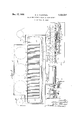
Fig. 1 is a diagrammatic longitudinal sectional elevation of a loop drier equipped in accordance with the principles of the present invention;
Fig. 2 is an enlarged transverse sectional elevation taken on the line 2-2, Fig. 1; and l5 Fig. 3 is a longitudinal sectional elevation taken on the line 3 3, Fig. 2.
In Fig. 1 of the accompanying drawing, the casing of a usual form of loop drier is diagrammatically illustrated at l. One of the side 20 chains, of which there is one at each side of the: drier to form a complete pole carrying conveyer, is illustrated at 2.
As ilustrated in Figs. 2 and 3, each of the pole carrying chains 2 comprises a series of 25 laterally spaced side links 3, 3 pivotally connected by pintles 4 which, in addition to forming the pivots between adjacent links, provide a bearing or axles for rollers 5, 5 by which the conveyer is supported on laterally spaced longi- 30 tudinally extending rails E, 6 disposed respectively adjacent the opposite sides of the drying chamber 'l within the drier casing l.
Projecting laterally from each or predetermined ones of the inside links 3a of each of 35 the carrier chains 2, 2, are studs 8 which are secured in the links 3a and afford rotary support or bearing for the opposite ends 9, 9 of each of the poles or girts I0, which latter extend transversely of the drying chamber 1 between the parallel side chains 2, 2.
One or each of the ends 9, 9 of each girt l0 is provided with a rectangular plate or wheel Il having diagonal corner slots I2, i2 radiating from the axis of girt lil and connected at their 45 outer ends by flat surfaces I3, I3 forming the outline or periphery of the rectangular wheel Il.
At predetermined spaced intervals along the upper run 2a of the conveyer 2 is a series of studs or pins HE- which, as the conveyer 2 advances and carries with it the poles I0 and square wheels ii, enter the lower forwardly extending corner slots I2, causing the square wheel Il and the pole attached thereto to turn to the extent of 90. 55
In order toprevent the flat-sided wheels II and poles IE) from turning more than 90 and to keep them from wolvering freely between such 90 rotations, a guide rail I5 is provided in spaced parallel relation to one or each of the supporting rails and is secured to said supporting rail at spaced intervals longitudinally thereof by brackets I6, which latter also provide support for the pole rotating studs I4.
The guide rail I 5 in each instance is preferably set just below the lowermost of the horizontally disposed surfaces I3 on the pole rotating wheels Il, with a slight clearance between the upper surface Il of the guide rail I5 and said lowermost surfaces I3 of the wheels II. Any tendency that the poles IQ may have to rotate intermediate the prescribed points at which the 90 rotations of the poles occur will be arrested by one of the ends or corners 5 of the lower at surface I3 of the wheel II of such pole engaging and riding on the upper surface II of the guide rail I5.
In order to permit of the 90 rotations of the poles I 0 at the above noted prescribed points, the rail I5 and the bracket I at each of the turning studs Id are correspondingly recessed as indicated at I i! in Figs. 2 and 3 to provide clearance for the points or corners I9 where the ilat faces I3 of the wheels II intersect with the vangular side walls of the corner slots I2 of said wheels, as clearly shown in Fig. 3.
As shown in Fig. l, the web X to be dried is fed by a drum or roll ZEE, through a feed opening 2l in the casing I, into the spaces between adjacently disposed poles I0, IU and as the conveyer 2 advances the poles in the direction of the arrow Fig. 1 the material X is draped over the advancing pole and falls between that and the next succeeding pole to form Vthe material into successive loops or festoons X between the poles.
As the poles advance the lower inclined surface of the lower forward corner slot I2 of each flat wheel Il associated with each pole I0 engages the stationary turning studs I4 one after another at the predetermined turning points respectively, whereby each pole, in turn, is given a quarterturn in`one direction as many times as may be `necessary during the travel of the loops X through the drying chamber 'l to prevent marking of the web by prolonged contact of the same parts of the web with the supporting girts Il).-
At the far end of the casing I the web is drawn out of the loops X and through a discharge opening 22 of the casing by any suitable means such as the drum or roll 23. Heated air is normally circulated through the casing I as by fans 2G, being heated in circulation by any of the well known devices, such as steam coils,
placed in the path of movement of the air,
rotations.
While the wheels I I have been shown as being four-sided, to give the poles the quarter-turns above noted, it is obvious that these turning wheels may have any desired number of flat sides and radial slots to turn the poles to any desired degree at each of the turning points; and while the guide rail I5 has been shown as being disposed below the path of movement of the wheels II it is obvious that said rail can be placed above the wheels with equal effectiveness.
I claim:
1. The combination in a loop drier, of a conveyer comprising loop supporting girts, means on the girts having perimetrical flat surfaces and radial recesses, means arranged to enter said recesses for intermittently partially rotating the girts, and means adapted to be engaged by said flat surfaces to prevent turning of the girts intermediate said partial rotations.
2. The combination in a loop drier, of a conveyer comprising loop supporting girts, end wheels on the girts having perimetrical at surfaces and radial recesses, means arranged Vto enter said recesses for intermittently partially rotating the girts, and means adapted to be engaged by said flat surfaces to prevent turning of the girts intermediate said partial rotations.
3. The combination in a loop drier, of a conveyer comprising looping supporting girts, means on the girts having perimetrical flat surfaces and radial recesses, studs disposed adjacent the path of the conveyer and arranged to enter said recesses for intermittently partially rotating the girts, and means adapted to be engaged by said at surfaces to prevent turning of the girts intermediate said partial rotations.
4. The combination in a loop drier, of a conveyer comprising loop supporting girts, means on the girts having perimetrical flat surfaces and radial recesses, means arranged to enter said recesses for intermittently partially rotating the girts, and a guide rail adjacent and paralleling the path of the conveyer and adapted to be engaged by said flat surfaces to prevent turning of the girts intermediate said partial rotations.V
5. The combination in a loop drier, of a conveyer comprising loop supporting girts, end Wheels on the girts having perimetrical fiat surfaces and radial recesses, studs disposed adjacent the path of the conveyer and arranged to enter said recesses for intermittently partially rotating the girts, and a guide rail adjacent and paralleling the path of the conveyer and adapted to be engaged by said flat surfaces to prevent turning of the girts intermediate said partial AlLlPHEUS` O. HURXTHAL.
Priority Applications (1)
| Application Number | Priority Date | Filing Date | Title |
|---|---|---|---|
| US743277A US2024927A (en) | 1934-09-08 | 1934-09-08 | Means for turning girts in loop driers |
Applications Claiming Priority (1)
| Application Number | Priority Date | Filing Date | Title |
|---|---|---|---|
| US743277A US2024927A (en) | 1934-09-08 | 1934-09-08 | Means for turning girts in loop driers |
Publications (1)
| Publication Number | Publication Date |
|---|---|
| US2024927A true US2024927A (en) | 1935-12-17 |
Family
ID=24988174
Family Applications (1)
| Application Number | Title | Priority Date | Filing Date |
|---|---|---|---|
| US743277A Expired - Lifetime US2024927A (en) | 1934-09-08 | 1934-09-08 | Means for turning girts in loop driers |
Country Status (1)
| Country | Link |
|---|---|
| US (1) | US2024927A (en) |
-
1934
- 1934-09-08 US US743277A patent/US2024927A/en not_active Expired - Lifetime
Similar Documents
| Publication | Publication Date | Title |
|---|---|---|
| US3956832A (en) | Web dryer arrangement | |
| US2671279A (en) | Drier | |
| US2024927A (en) | Means for turning girts in loop driers | |
| US1717004A (en) | Apparatus for stretching and drying weblike materials | |
| US1494307A (en) | Drying machine | |
| US2196921A (en) | Web handling apparatus | |
| US1958341A (en) | Roller conveyer | |
| US2767485A (en) | Veneer dryer | |
| US2270125A (en) | Drier for continuous web, strip, or string materials | |
| US1822158A (en) | Apparatus for drying sleeves | |
| US1504731A (en) | Drying machine | |
| US2996811A (en) | Gypsum wallboard manufacture | |
| US1989977A (en) | Machine for treating fabrics | |
| US1690439A (en) | Drying machine | |
| US2597490A (en) | Apparatus for treating textile materials | |
| US2133424A (en) | Method and apparatus for drying | |
| US2290053A (en) | Loop drier | |
| US3299533A (en) | Veneer dryer | |
| US1319077A (en) | Jotary drier | |
| US1952261A (en) | Loop forming device | |
| US1754483A (en) | Rotary can-end drier | |
| ES346289A1 (en) | Method and apparatus for drying goods in layers | |
| US881602A (en) | Machine for drying yarn and textile goods. | |
| US1407081A (en) | Textile-drying machine | |
| US1990406A (en) | Festooning mechanism for loop driers |