US2024903A - Banding mechanism - Google Patents
Banding mechanism Download PDFInfo
- Publication number
- US2024903A US2024903A US673765A US67376533A US2024903A US 2024903 A US2024903 A US 2024903A US 673765 A US673765 A US 673765A US 67376533 A US67376533 A US 67376533A US 2024903 A US2024903 A US 2024903A
- Authority
- US
- United States
- Prior art keywords
- article
- shaft
- tailstock
- articles
- ware
- Prior art date
- Legal status (The legal status is an assumption and is not a legal conclusion. Google has not performed a legal analysis and makes no representation as to the accuracy of the status listed.)
- Expired - Lifetime
Links
Images
Classifications
-
- B—PERFORMING OPERATIONS; TRANSPORTING
- B05—SPRAYING OR ATOMISING IN GENERAL; APPLYING FLUENT MATERIALS TO SURFACES, IN GENERAL
- B05C—APPARATUS FOR APPLYING FLUENT MATERIALS TO SURFACES, IN GENERAL
- B05C9/00—Apparatus or plant for applying liquid or other fluent material to surfaces by means not covered by any preceding group, or in which the means of applying the liquid or other fluent material is not important
- B05C9/02—Apparatus or plant for applying liquid or other fluent material to surfaces by means not covered by any preceding group, or in which the means of applying the liquid or other fluent material is not important for applying liquid or other fluent material to surfaces by single means not covered by groups B05C1/00 - B05C7/00, whether or not also using other means
- B05C9/022—Apparatus or plant for applying liquid or other fluent material to surfaces by means not covered by any preceding group, or in which the means of applying the liquid or other fluent material is not important for applying liquid or other fluent material to surfaces by single means not covered by groups B05C1/00 - B05C7/00, whether or not also using other means to obtain ornamental coatings
Landscapes
- Treatment Of Fiber Materials (AREA)
Description
Dec. 17, r M ALGEO BANDING MECHANISM I Filed May 51, 1953 s Sheets-Sheet 1 J I IIII-I Dec. 17,- 1935. A. M. ALGEO BANDING MECHANISM Filed-May 31, 1933 3 Sheets-Sheet 2 AZberZ/M AZgeo dbtomww Dec. 17, 1935. M. ALGEO BANDING MECHANI SM Filed May 31, 1935 3 Sheets-Sheet 3 A. gme/rfloz Albem fiiflggeo Patented Dec. 17, 1935 UNITED STATES rATENT OFFICE,
BANDING MECHANISM Application May 31, 1933, Serial No. 673,765
3 Claims.
In the decoration of ceramic ware, such as china and the like, by placing bands of coloring material thereon, it is usual to place the article on the center of a rotatably mounted table and 5 spin the table andsupported article while ap plying to the article a brush carrying the coloring material. In such method some difficulty is encountered in centering the article and the method itself is not such as will permit of a high rate of output.
The present invention relates to the application of bands of coloring material to glassware, china, or other ceramic ware, and has for its primary object to provide a mechanism which will support the articles to be decorated in a centered position for spinning and yet which will admit of rapid manipulation so as to greatly expedite the production of decorated articles.
A further object of the invention consists in the provision of a clamp for the articles which may be easily and quickly operated either to secure or release the articles being operated upon.
Another object of the invention consists of an M adjustable mechanism which will permit the articles to be spun on a horizontal axis, a vertical axis or any intermediate position most suitable to the particular shape of the articles being operated upon.
Other objects and advantages of the invention will be apparent from the following description when taken in connection with the accompanying drawings, in which,
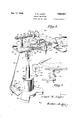
Figure 1 is a perspective view of the complete apparatus as adjusted for use in placing bands on cups or similar receptacles.
Figure 2 is a fragmentary elevational view showing the arm rest in use.
Figure 3 is a fragmentary elevational view partly in section showing the clamping mechanism in detail.
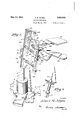
Figure 4 is a perspective view of the mechanism shown in Figures 1, 2 and 3 but with the apparatus arranged for decorating a different type of articles, such as saucers, plates, etc.
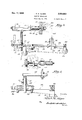
Figure 5 is a view similar to Figure 3 showing a slightly modified construction of clamp, and
Figure 6 is a detail view showing the manner of applying bands to articles mounted on the apparatus as arranged in Figure 4.
Referring to the drawings in greater detail and especially to Figures 1, 2 and 3, the numeral I indicates a base member provided with lateral extensions 2 of sufficient extent to firmly support the apparatus mounted thereon. Extendi s pw y from the base I is a socket member 3 provided with a set screw 4 for adjustably securing a rod 5 on which the apparatus is pivotally mounted.
The upper end of rod 5 is provided with a hinge knuckle 6 having an upturned edge I. A 5 complemental hinge knuckle 8 is pivotally connected to knuckle 6 by means of a bolt 9, and the design of the knuckles issuch that they may have a relative movement of 90 but no more. The knuckles t8 maybe locked against pivotal 10 movement by tightening up on the bolt 9. The upper end of the hinge member 8 is provided with a threaded portion l!) to which is secured a table ll; a clamping nut I2 serving to lock the table in position. By the hinge construction it 15 will be seen that the table may be adjusted from horizontal to vertical position or to any position intermediate these two extremes. Moreover, by loosening the nut t2 the table may be rotatably adjusted about the pin I0.
Fixedlymounted on the table II, in either of the apertures I3, is a headstock including a pedestal M which is secured in position by means of nuts I5. A double bearing I6 is fixed to the upper end of pedestal l4 and has mounted therein a shaft IT. The bearings l6 are perferably of the radial type to permit free rotary movement of the shaft at all times. Fixed on the end of shaft ll is a disc I8 forming a chuck or face plate for the reception of the base of the article being operated upon. This member I8 is preferably grooved as at i9 to provide a centering means for the articles.
Keyed to the shaft H is a cylindrical member 20 which is knurled on its outer surface as indicated by the numeral 2!. This element 20 serves as a gripping means for the fingers of the operator in spinning the shaft I1 and also, by reason of its weight, cooperates with the plate 18 to provide the necessary inertia for the shaft I1.
The tailstock of the mechanism is slidably mounted in a longitudinal slot 22 formed in the table II, which slot may be closed at its outer end by a crossbar 23. A crosshead 24 is provided with longitudinal grooves which receive the edges of the table bounding the slot 22, and a vertical opening through the crosshead receives the lower end of the tailstock pedestal 25. A set screw 26 provides the necessary vertical adjustment of the tailstock. The upper end of the element 25 is bent into horizontal positions as indicated by numeral 21, and has rotatably mounted thereon as by bearing 28 a head or mandrel 29. The bearing for the mandrel 29 is preferably of the self-aligning type to permit the head to automatchain has one end anchored to the cross-head 24 asindicated at 32' and then passes over guide pulleys 33 and 34 and has its opposite end secured to an eye 35 fixed on an operating pedal 36. The end of the chain is provided with a hook 31 adapted to engage in an appropriate link thereof to provide the necessary adjustment for various positions of the table II. By pressing the foot uponthe pedal 36 it will be obvious that the tailstock 21 is withdrawn against the tension of springs 30 to allow the removal of a'decorated article and the substitution of an article to be decorated. V
7 As will be readily understood, the band of col oring material is applied to the article by spinning the shaft IT with the article clamped thereon, and then holding the tipof the brush bearing the color against the article. Obviously some means forsteadying the arm of the operator is desirable in order to accurately position the band of color on the ware and for this purpose an arm rest consisting of an elongated plate 38 is provided. The plate 38 carries a bolt-receiving eye 39 on its'underside which cooperates with a similar eye 40 formed on a rod M which is adjustably mounted in a sleeve 42 as by means of a setscrew 43. A bolt 44 passing through the eyes 39 and 40 provides for angular adjustment of the arm rest 38 while the slotted bracket 45 and bolt 46 provide for its bodily adjustment with respect to the table I I. 7
A mixing tile or palette for the paint or other coloring material being applied to the ware is indicated by the numeral 41. This member 41 is mounted on an arm 48, and the latter is pivoted to the table II as indicated by numeral 49.
With the apparatus as thus far described and as shown in Figures 1, 2 and 3, the arm rest and palette are adjusted to substantially the positions indicated, and the tailstock operated in the manner heretofore described to permit a cup or other similar receptacle to be centered and clamped between the headstock and tailstock. The bearings in these members cause them to automatically adjust themselves to variations in the ware or elsewhere. The operator now spins the ware by applying a spinning movement to the 'member ZIl, and with his arm preferably resting on the plate 38 applies the tip of the brush to the article at the desired distance from the end thereof. The spinning of the ware will of course cause the band or stripe to be applied around its entire circumference in the plane selected.
If it is desired to place a band on a more or less fiat article such as a saucer the operation is greatly facilitated if the article is rotatedin a more or less horizontal'plane. It is primarily for this reason that some of the adjustments heretofore referred to have been embodied in the invention.
For instance, by referring to Figure 4 it will be seen that the hinge 68 has been operated through 90 to bring the table I I to vertical position and the table has been swung angularly about of the operator. Also, the bracket 45 is swung, to a more suitable angular position so as to better adapt the arm rest 38 to the Work; and in this connection it is to be noted that a rod 50 provided with a pivoted extension 5| is mounted in the 5 sleeve 42 in lieu of the rod 4! shown in Figure 1, thus providing a more flexible adjustment for the arm rest. And again, the arm 48 for the palette 41 is removed from its pin 49 and connected by a universal joint 52 with an arm 53 which is secured to the table by a bolt 54 in aperture 55 (Figure 1).
r In this arrangement of the apparatus for use with substantially fiat ware the change of the table II from horizontal to vertical position produces a certain amount of slack in the operating cable 32 of the tailstock, and in order to make the necessary adjustment the cable is drawn furticle is presented to the operator in a position best suited to the application of the brush. v
In applying bands to articles provided with large handles or in which for other reasons the weight is not equally distributed it is desirable to provide some means to insure a smooth spinning of the article if the band is to be properly applied, and a' modified construction for this purpose is shown in Figure 5. In this'form of the invention the shaft 60 of the headstock is provided with a suitable counter-weight 6| which is detachably connected to the shaft by a'clamp 62. The article to be banded will of course be mounted on the headstock with the handle diametrically opposed to the counter-weight, to insure a smooth turning of the shaft.
This modified form of headstock includes a baseplate 63 provided with a downwardly-extend ing rod 64 which is adjustably secured in the crosshead 24 by a set screw 65. The shaft 60 is mounted in a pair of radial bearings 66 fixed on the end of a vertical post 61 which has its lower end secured in a slot 68 in the base plate. A knurled drum 69 is secured to the outer end of shaft 60 for operating the same, and the inner end of the shaft, is provided with a face plate I0 and rubber cushion II for engaging the base of the article being operated upon.
From the above description and the accompanying drawings it will be apparent that an efficient and simple apparatus for centrally supporting and rotating ware during the banding operation has been provided; that the device may be readily adapted to the decoration of either flat or cylindrical ware as desired; that the articles may be released or clamped by movement of the parting from the spirit of the invention, and all such changes and modifications are intended to be included within the scope of the appended. [0 claims.
What is claimed is: a
1. Apparatus for banding ceramic ware including a base, a table pivoted to the base and adapted t9 be adjusted to'either a vertical or a hori 76 zontal position, means on the table for rotatabiy supporting for spinning movement a piece of work and including a slidably mounted tailstock, and foot-operated means for sliding the tailstock.
2. Apparatus for banding ceramic ware including a base, a table pivoted to the base and adapted to be adjusted to either a vertical or a horizontal position, means including a slidably mounted tailstock for rotatably supporting for spinning movement a piece of work, a pedal and cable for sliding the tailstock.
3. Apparatus for banding ceramic ware including a table, a post rising therefrom, a shaft rotatably mounted onthe upper end of the post, a face plate on the end of the shaft and forming part of an article clamp, and a counterbalance weight detachably secured to the shaft.
ALBERT M. ALGEO.
Priority Applications (1)
| Application Number | Priority Date | Filing Date | Title |
|---|---|---|---|
| US673765A US2024903A (en) | 1933-05-31 | 1933-05-31 | Banding mechanism |
Applications Claiming Priority (1)
| Application Number | Priority Date | Filing Date | Title |
|---|---|---|---|
| US673765A US2024903A (en) | 1933-05-31 | 1933-05-31 | Banding mechanism |
Publications (1)
| Publication Number | Publication Date |
|---|---|
| US2024903A true US2024903A (en) | 1935-12-17 |
Family
ID=24704033
Family Applications (1)
| Application Number | Title | Priority Date | Filing Date |
|---|---|---|---|
| US673765A Expired - Lifetime US2024903A (en) | 1933-05-31 | 1933-05-31 | Banding mechanism |
Country Status (1)
| Country | Link |
|---|---|
| US (1) | US2024903A (en) |
Cited By (4)
| Publication number | Priority date | Publication date | Assignee | Title |
|---|---|---|---|---|
| US2515359A (en) * | 1948-08-17 | 1950-07-18 | William F Steiner | Easel |
| US3848564A (en) * | 1973-07-18 | 1974-11-19 | L Kull | Rotating egg coloring device |
| US20120064253A1 (en) * | 2009-03-01 | 2012-03-15 | Hsu Shao-Hsien | Method for coloring recognizable tool bit |
| US20130270403A1 (en) * | 2012-04-11 | 2013-10-17 | Unites States Gypsum Company | Container mixing stand |
-
1933
- 1933-05-31 US US673765A patent/US2024903A/en not_active Expired - Lifetime
Cited By (5)
| Publication number | Priority date | Publication date | Assignee | Title |
|---|---|---|---|---|
| US2515359A (en) * | 1948-08-17 | 1950-07-18 | William F Steiner | Easel |
| US3848564A (en) * | 1973-07-18 | 1974-11-19 | L Kull | Rotating egg coloring device |
| US20120064253A1 (en) * | 2009-03-01 | 2012-03-15 | Hsu Shao-Hsien | Method for coloring recognizable tool bit |
| US20130270403A1 (en) * | 2012-04-11 | 2013-10-17 | Unites States Gypsum Company | Container mixing stand |
| US8876069B2 (en) * | 2012-04-11 | 2014-11-04 | United States Gypsum Company | Container mixing stand |
Similar Documents
| Publication | Publication Date | Title |
|---|---|---|
| CN111331447B (en) | Bathroom product shaping treatment facility of polishing | |
| US2024903A (en) | Banding mechanism | |
| US2209688A (en) | Decorating machine | |
| US1977704A (en) | Glazing machine | |
| US1660329A (en) | Holder for golf-club shafts and the like | |
| US2460136A (en) | Brush holder | |
| US5224691A (en) | Lamp shade soldering aid | |
| US2537922A (en) | Fixing of handles and other fittings to pottery articles | |
| US2896378A (en) | Grinding and polishing machine | |
| US1840466A (en) | Globe stamping apparatus | |
| US4057384A (en) | Clay centering device for a potter's wheel | |
| US2124011A (en) | Apparatus for stenciling | |
| US3097984A (en) | Tire retread material rolling machine | |
| US2098306A (en) | Apparatus for applying abrasive to polishing wheels, belts, or the like | |
| US1531365A (en) | Means for applying color stripes | |
| US1332778A (en) | Method of and means for preparing lenses and the like for grinding and polishing | |
| US2497228A (en) | Groove scraping device | |
| US3970508A (en) | Decal smoothing apparatus | |
| CN206870067U (en) | A kind of china cup split unit | |
| CN112223030A (en) | Jun porcelain inner wall grinding device | |
| US2045881A (en) | Glass banding machine | |
| US1267905A (en) | Cleaning-machine. | |
| US2836145A (en) | Apparatus for applying a bead to glass tumblers | |
| USRE20277E (en) | Banding machine | |
| US1477282A (en) | Hat marking |