US2022313A - Centrifugal fan - Google Patents
Centrifugal fan Download PDFInfo
- Publication number
- US2022313A US2022313A US1682A US168235A US2022313A US 2022313 A US2022313 A US 2022313A US 1682 A US1682 A US 1682A US 168235 A US168235 A US 168235A US 2022313 A US2022313 A US 2022313A
- Authority
- US
- United States
- Prior art keywords
- vanes
- vane
- inlet
- fan
- centrifugal fan
- Prior art date
- Legal status (The legal status is an assumption and is not a legal conclusion. Google has not performed a legal analysis and makes no representation as to the accuracy of the status listed.)
- Expired - Lifetime
Links
- 239000012530 fluid Substances 0.000 description 4
- 238000011144 upstream manufacturing Methods 0.000 description 4
- 238000010586 diagram Methods 0.000 description 2
- 241000555745 Sciuridae Species 0.000 description 1
- 230000000712 assembly Effects 0.000 description 1
- 238000000429 assembly Methods 0.000 description 1
- 230000006698 induction Effects 0.000 description 1
- 238000000034 method Methods 0.000 description 1
- 230000035945 sensitivity Effects 0.000 description 1
Images
Classifications
-
- F—MECHANICAL ENGINEERING; LIGHTING; HEATING; WEAPONS; BLASTING
- F04—POSITIVE - DISPLACEMENT MACHINES FOR LIQUIDS; PUMPS FOR LIQUIDS OR ELASTIC FLUIDS
- F04D—NON-POSITIVE-DISPLACEMENT PUMPS
- F04D29/00—Details, component parts, or accessories
- F04D29/40—Casings; Connections of working fluid
- F04D29/42—Casings; Connections of working fluid for radial or helico-centrifugal pumps
- F04D29/44—Fluid-guiding means, e.g. diffusers
- F04D29/46—Fluid-guiding means, e.g. diffusers adjustable
- F04D29/462—Fluid-guiding means, e.g. diffusers adjustable especially adapted for elastic fluid pumps
-
- F—MECHANICAL ENGINEERING; LIGHTING; HEATING; WEAPONS; BLASTING
- F04—POSITIVE - DISPLACEMENT MACHINES FOR LIQUIDS; PUMPS FOR LIQUIDS OR ELASTIC FLUIDS
- F04D—NON-POSITIVE-DISPLACEMENT PUMPS
- F04D29/00—Details, component parts, or accessories
- F04D29/40—Casings; Connections of working fluid
- F04D29/42—Casings; Connections of working fluid for radial or helico-centrifugal pumps
- F04D29/4206—Casings; Connections of working fluid for radial or helico-centrifugal pumps especially adapted for elastic fluid pumps
- F04D29/4213—Casings; Connections of working fluid for radial or helico-centrifugal pumps especially adapted for elastic fluid pumps suction ports
-
- F—MECHANICAL ENGINEERING; LIGHTING; HEATING; WEAPONS; BLASTING
- F05—INDEXING SCHEMES RELATING TO ENGINES OR PUMPS IN VARIOUS SUBCLASSES OF CLASSES F01-F04
- F05D—INDEXING SCHEME FOR ASPECTS RELATING TO NON-POSITIVE-DISPLACEMENT MACHINES OR ENGINES, GAS-TURBINES OR JET-PROPULSION PLANTS
- F05D2250/00—Geometry
- F05D2250/50—Inlet or outlet
- F05D2250/51—Inlet
Definitions
- the present invention relates to centrifugal fans and more particularly to fans having p'rovision for control of output by the use of inlet vanes of the type disclosed in my prior Patent No. 1,846,863,'dated February 23, 1932, and my co-pending application Serial No. 403,753, flied October 31, 1929.
- This application is a division of said application Serial No. 403,753, now Patent No. 1,989,413.
- the object of the present invention is to' provide control vanes which will require a minimum of power for their operation.
- the present invention comprises a centrifugal fan with control vanes in the inlet, the vanes being asymmetrically I pivoted with a preponderance of area on the downstream sides of their axes. It has been discovered that, with such an arrangement, it is possible to balance the forces so that a comparatively small amount of power is required for adjusting the vanes to any desired position.
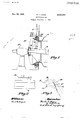
- Fig. 1 is a sectional elevation of so much of a fan of forced draft type as is necessary to illustrate the application of the present invention
- Fig. 2 is 2. diagrammatic developed plan view'of a portion of the rotor and vanes
- Fig. 3 is a diagram-' matic view illustrating the theory 01' the present invention.
- the fan illustrated in the drawing comprises a casing l and a rotor or wheel 6 mounted on a shaft 2 which is journaled in suitable bearings ll.
- the shaft is driven by a constant speed motor such as a squirrel cage induction motor, preferably directly connected to the end of the shaft.
- a constant speed motor such as a squirrel cage induction motor, preferably directly connected to the end of the shaft.
- an inlet cone or eye I! On each side of the casing is an inlet cone or eye I! through'which the air passes from the atmosphere into the rotor 6, only one of the inlet cones being shown inFig. 1.
- the casing is provided with any usual or preferred outlet connection.
- each inlet cone is provided with a plurality of overlapping vanes l6.
- each vane is in the general shape of a sector and'is provided with pivot pins-l8 and 20 at opposite ends. The outer pin it is journaled in the inlet cone I2 and the inner pin 20 is journaled in a cone-shaped hub 22 secured to the bearing.
- each pin I8 is Joumaled in a yoke 24 secured to the casing and each pin carries a bevel gear 26 which meshes with a bevel gear 28 mounted in a horizontal shaft 30 also journaled in the yoke.
- a plate 10 32 Secured to each gear 28 is a plate 10 32, the several plates being suitably connected bylinks to permit simultaneous operation of the vanes.
- each vane on the inner or downstream side of its axis, 15 that is, the side nearer the fan, is of greater area than the outer or upstream portion.
- the purpose of thus unbalancing the areas, on opposite sides of the axis is to permit opening and closing of the vanes with a minimum of effort. If the 20 vanes were symmetrically pivoted, there would be a considerable air force tending to keep the vanes closed.
- This is roughly illustrated by the diagram of Fig. 3 showing the streamlines of flow around a single vane inclined to the direc- 25 tion of flow. As in the usual picture of aerodynamic fiow, there is a streamline A which terminates on the surface of the vane at zero velocity.
- the streamlines B above theline A curl around the front edge of the vane in the 30 general manner indicated.
- the streamlines C below the line A curve smoothly toward and along the rear edge of the vane, the velocity increasing as indicated by the closer spacing of the lines as the rear edge is approached.
- the 35 streamlines are such as to give a rather complex pressure distribution over the vane.
- the pressure is nearly constant but on the front, the pressure is greatest at the point where the streamline A impinges on the 40 vane and tapers off on both sides of the line A.
- the velocity is high
- FIG. 3 is for a single vane and although the air flow may be considerably modified by the presence of a series of vanes, nevertheless the same general principles apply. If the vanes are pivoted on the median line, they are always subjected to strong closing forces.
- the axis of pivoting is placed at a point upstream from the middle 0, indicated as O.
- the streamline picture is unchanged, but the moments are now more nearly balanced, so that the vane can be moved from one position to another with relatively small effort.
- the best position of the pivot may be determined by graphically integrating the moments on both sides of the pivot. Such a graphical method is not usually feasible, however, because the pressure distribution over a number of adjacent vanes is enough different from the distribution over a single vane to vitiate any calculations. Furthermore, the distribution of pressure varies with the position of the vane, and in general the closing moments are strongest when the vanes are near closed position, that is, when the vanes are in a position to direct fluid tangentially of the rotor, or nearly so, as shown in Fig. 2.
- the location of the pivots is best determined experimentally.
- a set of vanes is tested with the pivots in several diflerent positions, and that position is chosen which gives most satisfactory operation over the whole range.
- a forced draft fan of the type illustrated it has been found that the area of each vane downstream from the pivot should be about 60% of the whole area of the vane. It is unnecessary to repeat the experimental work for each fan, since the same proportions hold for inlet assemblies of similar type, regardless of size.
- the best ratio may sometimes be as high as 70-30% or as low as 55-45%.
- the force required to hold the vanes in a desired position or to move the vanes from one position to another is as little as one-fifteenth of the force required for symmetrically pivoted vanes.
- the present invention therefore gives not only a savbut what is even more important. it permits the control apparatus to work at full sensitivity. 7
- a centrifugal fan comprising a casing having an inlet, a rotor, a plurality of vanes uni-,
- each vane being disposed K with sufficiently greater area on the downstream side of the axis of its pivotal mounting than on the upstream side thereof to substantially balance the turning moments due to the unevendistribution of pressure on each vane.
- a centrifugal fan comprising a casing having a converging inlet, a rotor, a plurality of vanes uniformly spaced in the inlet for imparting a controllable spin velocity to the entering fluid, a
- each vane perpendicular to the wall of the inlet and inclined to the axis of the rotor, and mechanism for simultaneously and uniformly adjusting the vanes from a wide open position through anangle of nearly 90 degrees to a' substantially closed pomtion, each vane being disposed with sumciently greater area on the downstream side of the axis of its pivotal mounting than on the upstream side thereof to substantially balance the turning moments due to the imeven distribution of pressure on each vane.
Landscapes
- Engineering & Computer Science (AREA)
- Mechanical Engineering (AREA)
- General Engineering & Computer Science (AREA)
- Structures Of Non-Positive Displacement Pumps (AREA)
Description
Nov. 26, 1935. H. F. HAGEN 2,022,313
CENTRIFUGAL FAN Original Filed Oct. 31, 1929 Patented Nov. 26, 1935 UNITED STATES.
PATENT OFFICE Original application October 31, 1929, Serial No.
403,753. Divided and this application January 14, 1935, Serial No. 1,682
2 Claims. (Cl. 230-114) The present invention relates to centrifugal fans and more particularly to fans having p'rovision for control of output by the use of inlet vanes of the type disclosed in my prior Patent No. 1,846,863,'dated February 23, 1932, and my co-pending application Serial No. 403,753, flied October 31, 1929. This application is a division of said application Serial No. 403,753, now Patent No. 1,989,413.
In control apparatus of this general type, it is found that the stream of air moving past the vanes gives rise to forces and moments which 7 tend to move the vanes toward closed position. As a consequence, excessive amounts of power are required to move the vanes from one position to another.
The object of the present invention is to' provide control vanes which will require a minimum of power for their operation.
With this object in view, the present invention comprises a centrifugal fan with control vanes in the inlet, the vanes being asymmetrically I pivoted with a preponderance of area on the downstream sides of their axes. It has been discovered that, with such an arrangement, it is possible to balance the forces so that a comparatively small amount of power is required for adjusting the vanes to any desired position.
In the accompanying drawing, Fig. 1 is a sectional elevation of so much of a fan of forced draft type as is necessary to illustrate the application of the present invention; Fig. 2 is 2. diagrammatic developed plan view'of a portion of the rotor and vanes; and Fig. 3 is a diagram-' matic view illustrating the theory 01' the present invention.
The fan illustrated in the drawing comprises a casing l and a rotor or wheel 6 mounted on a shaft 2 which is journaled in suitable bearings ll. The shaft is driven by a constant speed motor such as a squirrel cage induction motor, preferably directly connected to the end of the shaft. On each side of the casing is an inlet cone or eye I! through'which the air passes from the atmosphere into the rotor 6, only one of the inlet cones being shown inFig. 1. The casing is provided with any usual or preferred outlet connection.
o In order to control the output of the fan, each inlet cone is provided with a plurality of overlapping vanes l6. As shown in Fig. 2, each vane is in the general shape of a sector and'is provided with pivot pins-l8 and 20 at opposite ends. The outer pin it is journaled in the inlet cone I2 and the inner pin 20 is journaled in a cone-shaped hub 22 secured to the bearing.
The vanes in each set are adapted to be simui taneously adjusted to any desired inclination from fully closed to wide open position. To this 5 end, each pin I8 is Joumaled in a yoke 24 secured to the casing and each pin carries a bevel gear 26 which meshes with a bevel gear 28 mounted in a horizontal shaft 30 also journaled in the yoke. Secured to each gear 28 is a plate 10 32, the several plates being suitably connected bylinks to permit simultaneous operation of the vanes.
As shown in Figs. 1 and 2, the portion of each vane on the inner or downstream side of its axis, 15 that is, the side nearer the fan, is of greater area than the outer or upstream portion. The purpose of thus unbalancing the areas, on opposite sides of the axis is to permit opening and closing of the vanes with a minimum of effort. If the 20 vanes were symmetrically pivoted, there would be a considerable air force tending to keep the vanes closed. This is roughly illustrated by the diagram of Fig. 3 showing the streamlines of flow around a single vane inclined to the direc- 25 tion of flow. As in the usual picture of aerodynamic fiow, there is a streamline A which terminates on the surface of the vane at zero velocity. The streamlines B above theline A curl around the front edge of the vane in the 30 general manner indicated. The streamlines C below the line A curve smoothly toward and along the rear edge of the vane, the velocity increasing as indicated by the closer spacing of the lines as the rear edge is approached. The 35 streamlines are such as to give a rather complex pressure distribution over the vane. On the back of the vane, the pressure is nearly constant but on the front, the pressure is greatest at the point where the streamline A impinges on the 40 vane and tapers off on both sides of the line A. Near the rear edge, where the velocity is high,
there is actually a negative pressure. The uneven distribution of pressureis such that if the vane is pivoted at its middle 0, there are strong unbalanced moments tending to move the vane to a position perpendicular to the air stream.
Although the diagram of Fig. 3 is for a single vane and although the air flow may be considerably modified by the presence of a series of vanes, nevertheless the same general principles apply. If the vanes are pivoted on the median line, they are always subjected to strong closing forces.
According to the present invention, the axis of pivoting is placed at a point upstream from the middle 0, indicated as O. The streamline picture is unchanged, but the moments are now more nearly balanced, so that the vane can be moved from one position to another with relatively small effort.
If the pressure distribution on the vane is known, the best position of the pivot may be determined by graphically integrating the moments on both sides of the pivot. Such a graphical method is not usually feasible, however, because the pressure distribution over a number of adjacent vanes is enough different from the distribution over a single vane to vitiate any calculations. Furthermore, the distribution of pressure varies with the position of the vane, and in general the closing moments are strongest when the vanes are near closed position, that is, when the vanes are in a position to direct fluid tangentially of the rotor, or nearly so, as shown in Fig. 2. It cannot be expected, therefore, that the undesirable closing moments can be fully neutralized for all positions of the vanes, but it is possible to mount the vanes so that they may be moved from one positionto another with only a small fraction of the power that would be required for symmetrically mounted vanes.
Ina practical case, the location of the pivots is best determined experimentally. A set of vanes is tested with the pivots in several diflerent positions, and that position is chosen which gives most satisfactory operation over the whole range. In a forced draft fan of the type illustrated, it has been found that the area of each vane downstream from the pivot should be about 60% of the whole area of the vane. It is unnecessary to repeat the experimental work for each fan, since the same proportions hold for inlet assemblies of similar type, regardless of size.
It has been found, as the result of tests on a variety of fans, with inlet vanes of diflerent shapes, that although the 6040% ratio above,
mentioned is approximately correct for the type of vane herein shown, the best ratio may sometimes be as high as 70-30% or as low as 55-45%.
.with vanes of other shapes.
ing of power,
the force required to hold the vanes in a desired position or to move the vanes from one position to another is as little as one-fifteenth of the force required for symmetrically pivoted vanes. The present invention therefore gives not only a savbut what is even more important. it permits the control apparatus to work at full sensitivity. 7
Although the invention has been described and shown as applied to vanes of particular shape for a particular fan, the invention is not to be considered limited to such specific embodiment, except as limited by the appended claims.
Having thus described the invention, what is claimed is:
l. A centrifugal fan comprising a casing having an inlet, a rotor, a plurality of vanes uni-,
formly spaced with respect to the inlet for imparting a controllable spin velocity tothe ente ing fluid, a pivotal mounting for each vane, and mechanism for simultaneously and uniformly adlusting the vanes from a wide open position to a substantially closed position in which the fluid is directed by the vanes in a direction nearly tangentially of the rotor, each vane 'being disposed K with sufficiently greater area on the downstream side of the axis of its pivotal mounting than on the upstream side thereof to substantially balance the turning moments due to the unevendistribution of pressure on each vane.
2. A centrifugal fan comprising a casing having a converging inlet, a rotor, a plurality of vanes uniformly spaced in the inlet for imparting a controllable spin velocity to the entering fluid, a
pivotal mounting for each vane perpendicular to the wall of the inlet and inclined to the axis of the rotor, and mechanism for simultaneously and uniformly adjusting the vanes from a wide open position through anangle of nearly 90 degrees to a' substantially closed pomtion, each vane being disposed with sumciently greater area on the downstream side of the axis of its pivotal mounting than on the upstream side thereof to substantially balance the turning moments due to the imeven distribution of pressure on each vane.
HAROLD F. HAGEN.
Priority Applications (1)
| Application Number | Priority Date | Filing Date | Title |
|---|---|---|---|
| US1682A US2022313A (en) | 1929-10-31 | 1935-01-14 | Centrifugal fan |
Applications Claiming Priority (2)
| Application Number | Priority Date | Filing Date | Title |
|---|---|---|---|
| US403753A US1989413A (en) | 1929-10-31 | 1929-10-31 | Centrifugal fan |
| US1682A US2022313A (en) | 1929-10-31 | 1935-01-14 | Centrifugal fan |
Publications (1)
| Publication Number | Publication Date |
|---|---|
| US2022313A true US2022313A (en) | 1935-11-26 |
Family
ID=26669350
Family Applications (1)
| Application Number | Title | Priority Date | Filing Date |
|---|---|---|---|
| US1682A Expired - Lifetime US2022313A (en) | 1929-10-31 | 1935-01-14 | Centrifugal fan |
Country Status (1)
| Country | Link |
|---|---|
| US (1) | US2022313A (en) |
-
1935
- 1935-01-14 US US1682A patent/US2022313A/en not_active Expired - Lifetime
Similar Documents
| Publication | Publication Date | Title |
|---|---|---|
| US2337861A (en) | Propeller | |
| US2435236A (en) | Superacoustic compressor | |
| US3178131A (en) | Aircraft wing structure | |
| US2702986A (en) | Device for deflecting a fluid from its normal direction of flow | |
| BR102015011143A2 (en) | deflector for a sugar cane harvester, and sugar cane cleaning arrangement | |
| US2978206A (en) | Radial flow lift device | |
| US3019963A (en) | Radial blower for gases with high dust content | |
| US1868832A (en) | Aircraft | |
| US2223744A (en) | Wing and similar construction | |
| US1935097A (en) | Air turbine | |
| CN102834623A (en) | Peripheral control ejector | |
| US1989413A (en) | Centrifugal fan | |
| US1846379A (en) | Apparatus and method of controlling fans | |
| SE443842B (en) | AXIAL SPOT WITH A SPECIAL DESIGN OF THE OUTLET CHAMBER | |
| US2060289A (en) | Conditioning apparatus | |
| US1993419A (en) | Aircraft | |
| NO320132B1 (en) | Device for directional air flow 90 degrees | |
| US2687687A (en) | Back draft damper for exhaust fans | |
| US2022313A (en) | Centrifugal fan | |
| US1846863A (en) | Fan and method of operating the same | |
| US6866480B2 (en) | Centrifugal fan | |
| CN214007550U (en) | Fan system and range hood with same | |
| US3572613A (en) | Circular wing aircraft | |
| CN109505801A (en) | Asymmetric both sides air inlet impeller, centrifugal blower and kitchen ventilator | |
| US2050700A (en) | Centrifugal fan |