US2022084A - Arc striking control - Google Patents
Arc striking control Download PDFInfo
- Publication number
- US2022084A US2022084A US672752A US67275233A US2022084A US 2022084 A US2022084 A US 2022084A US 672752 A US672752 A US 672752A US 67275233 A US67275233 A US 67275233A US 2022084 A US2022084 A US 2022084A
- Authority
- US
- United States
- Prior art keywords
- welding
- arc
- electrode
- work
- contact
- Prior art date
- Legal status (The legal status is an assumption and is not a legal conclusion. Google has not performed a legal analysis and makes no representation as to the accuracy of the status listed.)
- Expired - Lifetime
Links
- 238000003466 welding Methods 0.000 description 82
- 239000004020 conductor Substances 0.000 description 8
- 238000010891 electric arc Methods 0.000 description 8
- 239000000463 material Substances 0.000 description 4
- 240000000662 Anethum graveolens Species 0.000 description 1
- 238000009413 insulation Methods 0.000 description 1
- QWXYZCJEXYQNEI-OSZHWHEXSA-N intermediate I Chemical compound COC(=O)[C@@]1(C=O)[C@H]2CC=[N+](C\C2=C\C)CCc2c1[nH]c1ccccc21 QWXYZCJEXYQNEI-OSZHWHEXSA-N 0.000 description 1
- 230000002093 peripheral effect Effects 0.000 description 1
Images
Classifications
-
- B—PERFORMING OPERATIONS; TRANSPORTING
- B23—MACHINE TOOLS; METAL-WORKING NOT OTHERWISE PROVIDED FOR
- B23K—SOLDERING OR UNSOLDERING; WELDING; CLADDING OR PLATING BY SOLDERING OR WELDING; CUTTING BY APPLYING HEAT LOCALLY, e.g. FLAME CUTTING; WORKING BY LASER BEAM
- B23K9/00—Arc welding or cutting
- B23K9/14—Arc welding or cutting making use of insulated electrodes
Definitions
- FIG -1 m1 5 v I T R W m WNKQWM ATTORNEY Patented Nov. 26, 1935 UNlTEDi STATES PATENT OFFICE 2,022,084 ARC STRIKING CONTROL Robert K. Hopkins, New York, N. Y., assignor to M. W. Kellogg 00., New York, N. Y a corporation of Delaware Application May 25, 1933, Serial No. 672,752 '1 Claims. (Cl. 219-8)
- This invention relates to electric arc welding blue with the arc control arrangements of the' and in particular to electric arc welding by automatic welding heads commercially 'manumeans of covered welding electrodes.
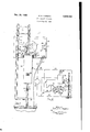
- the h w my invention in connection with an autoconditions at the arc when the arc is initiall matic arc ,welding ma h arranged to p y struck are substantially the same as when bare a continuous Welding electrode.
- 01 indefinite welding electrodes are used, however, when the lengthare is running because of the ionization of th Automatic arc welding machine 1 includes a elements of the covering material the conditions panel 2 that is fastened to pp o s w at the are are greatly changed.
- a electrode feeding m r l is of the arc control arrangements .which is adm u d on a bracket fixedto panel d has justed to maintain the running arc is not satis-- fastened to its drive shaft an electrode feeding factory for striking and establishing the arc.
- Wheel 5 The peripheral Portion of Wheel 5 is I have found that the troubles eigperienced preferably made of rubber, or similar material, during the striking of the arc with covered weldas not to injure the ti g ove ing electrodes can be avoided and the arc struck 1 of Welding electrode much in the same mann r as it bare welding Electrode 8 is made up of a plurality of secelectrodes by applying t t are control tions which are easly connectable one to the rangements a higher voltage setting, during the other, as for instance by the screw joint 9.
- each establi hm t of th arc, t is used while we1d section includes a metallic core land a covering, ing I therefor of non-conducting material of suitable composition.
- a wheel l l simil'ar to wheel bears on of the arc control arrangements during the estabtrode a prevents slippage between wheel 5 lishment of the arc, so that after the initial strikand electrode a wheel H is supported ing of the arc the feeding of the welding electrode t ti i ember l2 which has' one end pivoted is retarded to increase the length of the arc and in pivot member l3.
- Pivot member I3 is carried by a support member It is also an object of this invention to com- 15 which is positioned in brackets l6 fastened connected to roller 20.
- contact device I 9 includes a plurality electrode 8 on their way to the arc and pass the welding current through them to core ID.
- a sufficient number of pairs of rollers 20 are provided to continuously pass the welding current to core "I.
- Contact device l9 will not be de- Welding current generator 2
- the current for operating electrode feeding motor 4 passes to the control arrangements within casing 25 through line 23 and to motor 4 may be interrupted at will. trol arrangements within casing 25 are connected to cable 22 through conductor 29.
- is connected through conductor 32 to fixed contact member 33 of relay 34, the other fixed contact member 35 of which is connected through conductor 35 to the middle terminal of adjustable resistance 3
- the movable member 31 of relay 34 is electrically connected to conductor 38 which in turn is connected to cable 23.
- Choke 39 is tact end of the coil of choke 39 is connected to cable 22 through conductor 48, the other end being connected to cable 23 through conductor 4!.
- has been shown as
- On the other side of movable contact member 31 is fastened one end of a spring 42 the other end of which is anchored to a fixed part 01' the machine I.
- Spring 42 is of such strength that it will move movable contact member 31 out of contact with fixed contact member fixed contact member 33 when the pull exerted by choke 39 lessens due to welding electrode 8 touching work 3.
- Movable contact member 31 has also connected to it, through a suitable linkage,
- control arrangements within casing 25 are adjusted as required and adjustable the voltage setting necessary for the arc of predetermined length. After which 20 switch 28 is closed and a section of welding electrode 8 is passed through guides IT to feeding wheel 6. Feeding wheel 6 will pass the section of welding electrode 8 through contact device I3 to work 3. Care should be taken to assure that 25 the exposed areas of the section are aligned with rollers 20. Switch 24 is then closed.
- choke 39 will be energized and movable contact member 31 will be in contact with fixed contact member 35 so that the resist- 30 ance in the circuit of the arc control arrangements is such as corresponds to the voltage setting of the arc of predetermined length.
- the iiowof current through the 35 coil of choke 39 will be reduced to a minimum and its pull will no longer be sufficient to overcome the pull or spring 42 with the result that movable contact member 31 will move into contact with fixed contact member 33.
- the 40 are control arrangements will be subject to a much higher voltage setting since all of the resistance of adjustable resistance 3
- the efiect of the high voltage setting is to decrease the feed 45 of the welding electrode and consequently the arc will increase in length.
- welding current supply means elemen s ju t mentioned may be located within means connecting one side of said welding curo in 2 rent supply means to the work, means for con- 1 claim: necting the other side of said welding current'lil In electric ar Welding pp u means for supply means to said electrode as it passes to feeding an e ode o the W means dthe work, means for controlling said electrode ing an electrical circuit for controlling said elecfeeding means to maintain an are of predetertrodo f in me n to ma n ain an rc f pr mined length, means connecting said control determined length, and means for increasing the means to one side of the welding current supply resistance of said circuit during a predetermined ean a resistance having a terminal at each i v after Striking the '0- end thereof and a terminal intermediate its ends,
- welding current supply means a welding member in contact with said one of said fixed electrode having a covering of non-conducting contact members until the arc exceeds the prematerial, means for feeding the electrode to the determined length. arc, means for passing the welding current from 6.
- said electrode feeding means to maintain an arc fusible electrode, means for feeding the electrode of predetermined length, means connecting said to the work, welding current supply means, means control means to one side of said welding current connecting one side of Said Welding rr n 1 D- supply means, a resistance having a terminal at ply means to the work, means for connecting the each end thereof and a terminal intermediate its other side of said welding current supply means ends, means connecting said control means to one to said electrode as it passes to the work, means of said end terminals, and means connected to for controlling said electrode feeding means to the other side of said welding current supply maintain an arc of prede length, means means adapted during welding to connect to said connecting said control means to one side of said intermediate terminal and during the establishing current supply means, a resistance having a terof
- welding current supply means means connecting one side'of said welding current supply means to the work, means for connecting the spaced fixed contact members, means connecting the other of said end terminals to one of said 0 the other side of said current supply means, 5
Landscapes
- Engineering & Computer Science (AREA)
- Physics & Mathematics (AREA)
- Plasma & Fusion (AREA)
- Mechanical Engineering (AREA)
- Arc Welding Control (AREA)
Description
NOV. 26, 1935. R, K, HQPKINS 2,022,084
ARC STRIKING CONTROL Filed May 25, 1933 ,2 M s 5 l 18 I jib 13% 66 Q P e ff Dill?! 50 T 51 sai 255% 55 so 42 59 45 a? IT Tl FIG. -Zl
FIG -1 m1 5 v I T R W m WNKQWM ATTORNEY Patented Nov. 26, 1935 UNlTEDi STATES PATENT OFFICE 2,022,084 ARC STRIKING CONTROL Robert K. Hopkins, New York, N. Y., assignor to M. W. Kellogg 00., New York, N. Y a corporation of Delaware Application May 25, 1933, Serial No. 672,752 '1 Claims. (Cl. 219-8) This invention relates to electric arc welding blue with the arc control arrangements of the' and in particular to electric arc welding by automatic welding heads commercially 'manumeans of covered welding electrodes. factured, automatic means which are operable It has been found that the automatic welding substantially immediately after the initial strikheads which are at present manufactured c ming if the arc to insert resistance in the circuit mercially are unable to establish an are when of the arc control arran and maintain using a covered welding electrode as eiiectively as said resistance in sa d u t for a definite p when using a bare welding ele tr d with riod of time, and after the lapse of said period these automatic welding heads very little trouble of time em ve e s r e resistance Out Of said 15 p n ed either in establishing or maincircuit and allow said circuit to be influenced by 10 taining anarc of predetermined length when the voltage setting required to obtain and mainbare welding electrodes are used. However, tain the arc of desired len when covered electrodes are used these automatic The nvent on wi l b b tt und d and its welding heads, although they are capable of further objects and advantages appreciated from maintaining an arc of predetermined length, d a consideration of the following descriptiontaken not readily establish it. The initial arc with w h he acc mpanying drawing, i wh covered welding electrodes is usually very short 1 is e front elevation of an automatic are and in some cases the welding electrode buries welding machin o whi h my nv n has been itself into the work. This is probably due to the ap and fact that with bare welding electrodes the condi- Fi 2 is a d a a ma representation of the tions atthe are when the arc is initially struck mach ne of Fig. 1. and when the arc is running are substantially, T P t invention y b used with all the same, whereas with covered welding electyp s f aut mati a c w ldin ma i e a trodes the conditions at the are when the arc is a d t mpl y v d w d electrodesinitially struck and when the arc is running are For P p Of this disclosure 1 have Chosen to different. With covered welding electrodes the h w my invention in connection with an autoconditions at the arc when the arc is initiall matic arc ,welding ma h arranged to p y struck are substantially the same as when bare a continuous Welding electrode. 01 indefinite welding electrodes are used, however, when the lengthare is running because of the ionization of th Automatic arc welding machine 1 includes a elements of the covering material the conditions panel 2 that is fastened to pp o s w at the are are greatly changed. Thus with which may be fi d in Position movable relecovered welding electrodes the voltage setting tive to Work A electrode feeding m r l is of the arc control arrangements .which is adm u d on a bracket fixedto panel d has justed to maintain the running arc is not satis-- fastened to its drive shaft an electrode feeding factory for striking and establishing the arc. Wheel The peripheral Portion of Wheel 5 is I have found that the troubles eigperienced preferably made of rubber, or similar material, during the striking of the arc with covered weldas not to injure the ti g ove ing electrodes can be avoided and the arc struck 1 of Welding electrode much in the same mann r as it bare welding Electrode 8 is made up of a plurality of secelectrodes by applying t t are control tions which are easly connectable one to the rangements a higher voltage setting, during the other, as for instance by the screw joint 9. Each establi hm t of th arc, t is used while we1d section includes a metallic core land a covering, ing I therefor of non-conducting material of suitable composition. As shown non-conducting It IS an oblect of this invention to combine wlth covering 1 is scored at spaced intervals to expose the arc control arrangements of the automatic welding heads commercially manufactured, :gtggszgg: 233%; m for the passage of means for increasing the resistance in the circuit A wheel l l simil'ar to wheel bears on of the arc control arrangements during the estabtrode a prevents slippage between wheel 5 lishment of the arc, so that after the initial strikand electrode a wheel H is supported ing of the arc the feeding of the welding electrode t ti i ember l2 which has' one end pivoted is retarded to increase the length of the arc and in pivot member l3. A spring I constantly th r by pr v nt h u u y hort initial are r maintains wheel H in contact with electrode a. the burying of the welding electrode in the work. Pivot member I3 is carried by a support member It is also an object of this invention to com- 15 which is positioned in brackets l6 fastened connected to roller 20.
35 and into contact with them contact device [9, suitable insulation being provided between brackets l8 and contact device I!) to electrically insulate contact device [9 from Contact device I 9 includes a plurality electrode 8 on their way to the arc and pass the welding current through them to core ID. A sufficient number of pairs of rollers 20 are provided to continuously pass the welding current to core "I. Contact device l9 will not be de- Welding current generator 2| is mounted in the rear of panel 2 and has one side connected to work 3 by cable 22, the other side being connected to contact device 19 and rollers 20 through cable The current for operating electrode feeding motor 4 passes to the control arrangements within casing 25 through line 23 and to motor 4 may be interrupted at will. trol arrangements within casing 25 are connected to cable 22 through conductor 29.
The other end terminal of resistance 3| is connected through conductor 32 to fixed contact member 33 of relay 34, the other fixed contact member 35 of which is connected through conductor 35 to the middle terminal of adjustable resistance 3|. The movable member 31 of relay 34 is electrically connected to conductor 38 which in turn is connected to cable 23.
the period required to reestablish the arc. 15
Prior to the commencement of the welding operation the control arrangements within casing 25 are adjusted as required and adjustable the voltage setting necessary for the arc of predetermined length. After which 20 switch 28 is closed and a section of welding electrode 8 is passed through guides IT to feeding wheel 6. Feeding wheel 6 will pass the section of welding electrode 8 through contact device I3 to work 3. Care should be taken to assure that 25 the exposed areas of the section are aligned with rollers 20. Switch 24 is then closed.
At this time choke 39 will be energized and movable contact member 31 will be in contact with fixed contact member 35 so that the resist- 30 ance in the circuit of the arc control arrangements is such as corresponds to the voltage setting of the arc of predetermined length. When welding electrode 8 touches work 3 as the arc is initially struck, the iiowof current through the 35 coil of choke 39 will be reduced to a minimum and its pull will no longer be sufficient to overcome the pull or spring 42 with the result that movable contact member 31 will move into contact with fixed contact member 33. At this time the 40 are control arrangements will be subject to a much higher voltage setting since all of the resistance of adjustable resistance 3| is now in the circuit of the arc control arrangements. The efiect of the high voltage setting is to decrease the feed 45 of the welding electrode and consequently the arc will increase in length.
As welding electrode 8 separates from work 3 the resistance 01' the welding current path will increase with the result that current flow 50 through the coil of choke 38 as well as the pull of choke 33 will increase. However due to definite time delay device 43 movable contact 31 will not immediately move to fixed contact 35 but the predetermined length so that after movable contact member 31 moves back to fixed contact member 35, to place the arc control arrangements 50 under the influence of the voltage setting recare being taken to align the exposed areas oi. the 75 sections. This is repeated from time to time as movable contact member with the other side of required and the welding carried out as long as is said welding current supply. necessary. 5. In combination with electric arc welding ap- In Fig. 2 I have shown adjustable resistance 3|, paratus adapted to carry on welding by means relay 34, choke 39 and definite time delay device of an arc struck between the work and a cov- 5 43 as located Out id of ca n 5- T h b ered fusible electrode, means for feeding the elecdOhe tI p y the disclosul'e- If desired. the trode to the work, welding current supply means, elemen s ju t mentioned may be located Within means connecting one side of said welding curo in 2 rent supply means to the work, means for con- 1 claim: necting the other side of said welding current'lil In electric ar Welding pp u means for supply means to said electrode as it passes to feeding an e ode o the W means dthe work, means for controlling said electrode ing an electrical circuit for controlling said elecfeeding means to maintain an are of predetertrodo f in me n to ma n ain an rc f pr mined length, means connecting said control determined length, and means for increasing the means to one side of the welding current supply resistance of said circuit during a predetermined ean a resistance having a terminal at each i v after Striking the '0- end thereof and a terminal intermediate its ends,
n Combi a th electric arc Welding P- means connecting one of said end terminals to p Welding current pp y means, 8 Welding said control means, a pair of spaced fixed conelectrode having a covering of non-conducting tact members, means connecting the other of material, means for feeding the electrode to the aid end t rmin l to on f aid fixed ta t, arc, means for passing the welding current from members, means connecting the other of said said welding current supply means to said elecfixed contact members to the intermediate tertrode on its way to the are, means for controlling minal, a movable contact member, means consaid electrode feeding means to maintain an arc necting said movable contact member to the other 8 of predetermined length, means connecting said side of said current supply means, means concontrol means to one side of said'current supply 7 stantly urging said movable contact member into means, means connecting said control means to contact with said one of said fixed contact memthe other side of welding current supply means, bers, energizable means effective during welding a resistance in said second connecting means, and open circuit to urge said movable contact 80 and means for increasing the value of said remember into contact with said other of said fixed sistance upon striking and during the establishing contact members, said energizable means exertof the arc. ing a greater pull than said constantly urging 3. In combination with electric arc welding apmeans, and means holding said movable contact paratus, welding current supply means, a welding member in contact with said one of said fixed electrode having a covering of non-conducting contact members until the arc exceeds the prematerial, means for feeding the electrode to the determined length. arc, means for passing the welding current from 6. In combination with electric arc welding apsaid welding current supply means to said elecparatus adapted to carry on welding by means trode on its way to the arc, means for controlling of an arc struck between the work and a covered 40 said electrode feeding means to maintain an arc fusible electrode, means for feeding the electrode of predetermined length, means connecting said to the work, welding current supply means, means control means to one side of said welding current connecting one side of Said Welding rr n 1 D- supply means, a resistance having a terminal at ply means to the work, means for connecting the each end thereof and a terminal intermediate its other side of said welding current supply means ends, means connecting said control means to one to said electrode as it passes to the work, means of said end terminals, and means connected to for controlling said electrode feeding means to the other side of said welding current supply maintain an arc of prede length, means means adapted during welding to connect to said connecting said control means to one side of said intermediate terminal and during the establishing current supply means, a resistance having a terof the arc to connect to said other end terminal. minal at each end the and a terminal 4. In combination with electric arc welding aptermediate its ends, means connecting one of said v paratus, welding current supply means, a weldterminals to said control means, a pair of spaced ing electrode having a covering of non-conductfi contact members. means connecting the ing material, means for feeding th l t od t other of said end terminals to one of said fixed are, means for passing the welding current from contact members, means connecting the other said welding current supply means to said elecof said fixed contact members to said interme trode on its way to the arc, means for controlling diate terminal, a movable contact member, me s said electrode feeding means to maintain an are connecting said movable Contact emb to the of predetermined length, means connecting said other Side Of Said pply means, an control means to one side of said welding current normally urging said movable contact member rent supply means, a resistance having a-terminal into Contact with said one fixed Contact at each end thereof and a terminal intermediate means connected to both Sides of Said weld" ing current supply means adapted to exert a pull i 33 6 gzg'g gg iffxfii z g 333 $322; on said movable contact member suflicient to fixed contact members, means connecting one of xgzg g gi ggfg zgg fg gi ggg i i i g said fixed contact members to the other of said tact with said other Contact i. when the end terminals, means connecting the other of welding circuit is open and during welding but said fixed contact members to said intermediate i umclent, to Overcome said normally urging terminal, a movable Contact member adapted means when the welding circuit is initially closed,
contact with said other of said fixed contact d means for holding aid m ble o t ct members during welding and to contact with said member in contact with said one fixed contact one of said fixed contact members during estabmember for a predetermined interval of time lishing of the arc, and means connecting said after the welding circuit is closed.
7. In combination with electric arc welding apparatus adapted to carry on the welding by means of an arc struck between the work and a covered fusible electrodeg'means for feeding the electrode to the work, welding current supply means, means connecting one side'of said welding current supply means to the work, means for connecting the spaced fixed contact members, means connecting the other of said end terminals to one of said 0 the other side of said current supply means, 5
current supply means adapted to be energized on open welding circuit and during welding to 10 with said one fixed contact member for a definite 15 period of time after the welding circuit is closed.
ROBERT K. HOPKINS.
Priority Applications (1)
| Application Number | Priority Date | Filing Date | Title |
|---|---|---|---|
| US672752A US2022084A (en) | 1933-05-25 | 1933-05-25 | Arc striking control |
Applications Claiming Priority (1)
| Application Number | Priority Date | Filing Date | Title |
|---|---|---|---|
| US672752A US2022084A (en) | 1933-05-25 | 1933-05-25 | Arc striking control |
Publications (1)
| Publication Number | Publication Date |
|---|---|
| US2022084A true US2022084A (en) | 1935-11-26 |
Family
ID=24699861
Family Applications (1)
| Application Number | Title | Priority Date | Filing Date |
|---|---|---|---|
| US672752A Expired - Lifetime US2022084A (en) | 1933-05-25 | 1933-05-25 | Arc striking control |
Country Status (1)
| Country | Link |
|---|---|
| US (1) | US2022084A (en) |
-
1933
- 1933-05-25 US US672752A patent/US2022084A/en not_active Expired - Lifetime
Similar Documents
| Publication | Publication Date | Title |
|---|---|---|
| US4300036A (en) | Welding apparatus with arc interval energy control | |
| US3141085A (en) | Work-in-circuit consumable electrode arc welding | |
| US2460990A (en) | Automatic electric fusion welding apparatus and process | |
| JP2899371B2 (en) | Arc welding power supply | |
| US2007751A (en) | Automatic arc welding | |
| US3851137A (en) | Welding apparatus with consumable welding wire | |
| US1933936A (en) | Welding apparatus | |
| US3627975A (en) | Arc-welding apparatus | |
| US2022084A (en) | Arc striking control | |
| JPS6226867B2 (en) | ||
| US2145010A (en) | Automatic electric welding | |
| US3250894A (en) | Method and apparatus for monitoring short circuits in electric arc welding | |
| US2597689A (en) | Arc starting system | |
| CA1151271A (en) | Wire feeding apparatus for welders | |
| US4049899A (en) | Apparatus for uniformly heating molten glass | |
| US2339051A (en) | Discharge lamp apparatus | |
| US2627035A (en) | Milliamperage stabilizer | |
| US3317703A (en) | Welding circuit | |
| US2210786A (en) | Automatic arc welding | |
| US1571924A (en) | Automatic welder | |
| US1712114A (en) | Process of and apparatus for electric-arc welding | |
| US2433678A (en) | Electric arc welding | |
| US1687492A (en) | Electric welding apparatus | |
| US1549450A (en) | Control system for welding apparatus | |
| US2976395A (en) | Electrical welding apparatus |