US20200292774A1 - Installation of small form factor fibers at user premises - Google Patents
Installation of small form factor fibers at user premises Download PDFInfo
- Publication number
- US20200292774A1 US20200292774A1 US16/432,270 US201916432270A US2020292774A1 US 20200292774 A1 US20200292774 A1 US 20200292774A1 US 201916432270 A US201916432270 A US 201916432270A US 2020292774 A1 US2020292774 A1 US 2020292774A1
- Authority
- US
- United States
- Prior art keywords
- distal end
- adhesive
- fiber
- tool device
- syringe
- Prior art date
- Legal status (The legal status is an assumption and is not a legal conclusion. Google has not performed a legal analysis and makes no representation as to the accuracy of the status listed.)
- Granted
Links
- 239000000835 fiber Substances 0.000 title claims abstract description 144
- 238000009434 installation Methods 0.000 title description 22
- 239000000853 adhesive Substances 0.000 claims abstract description 115
- 230000001070 adhesive effect Effects 0.000 claims abstract description 115
- 239000013307 optical fiber Substances 0.000 claims abstract description 33
- 239000011248 coating agent Substances 0.000 claims abstract description 7
- 238000000576 coating method Methods 0.000 claims abstract description 7
- 238000004891 communication Methods 0.000 claims abstract description 3
- 230000014759 maintenance of location Effects 0.000 claims description 10
- 230000000717 retained effect Effects 0.000 claims description 6
- 238000007789 sealing Methods 0.000 claims description 5
- 239000011324 bead Substances 0.000 description 7
- 238000000465 moulding Methods 0.000 description 7
- 238000000034 method Methods 0.000 description 5
- 238000004804 winding Methods 0.000 description 5
- 230000013011 mating Effects 0.000 description 4
- XLYOFNOQVPJJNP-UHFFFAOYSA-N water Substances O XLYOFNOQVPJJNP-UHFFFAOYSA-N 0.000 description 3
- 238000007792 addition Methods 0.000 description 2
- 230000009194 climbing Effects 0.000 description 2
- 238000011900 installation process Methods 0.000 description 2
- 238000012986 modification Methods 0.000 description 2
- 230000004048 modification Effects 0.000 description 2
- 230000003287 optical effect Effects 0.000 description 2
- 238000010408 sweeping Methods 0.000 description 2
- 229920002292 Nylon 6 Polymers 0.000 description 1
- 239000004743 Polypropylene Substances 0.000 description 1
- 230000007423 decrease Effects 0.000 description 1
- 238000000151 deposition Methods 0.000 description 1
- 238000001746 injection moulding Methods 0.000 description 1
- 239000000463 material Substances 0.000 description 1
- 231100000252 nontoxic Toxicity 0.000 description 1
- 230000003000 nontoxic effect Effects 0.000 description 1
- 239000004033 plastic Substances 0.000 description 1
- 229920003023 plastic Polymers 0.000 description 1
- -1 polypropylene Polymers 0.000 description 1
- 229920001155 polypropylene Polymers 0.000 description 1
- 239000012858 resilient material Substances 0.000 description 1
- 239000000344 soap Substances 0.000 description 1
- 239000000243 solution Substances 0.000 description 1
- 239000012815 thermoplastic material Substances 0.000 description 1
Images


Classifications
-
- G—PHYSICS
- G02—OPTICS
- G02B—OPTICAL ELEMENTS, SYSTEMS OR APPARATUS
- G02B6/00—Light guides; Structural details of arrangements comprising light guides and other optical elements, e.g. couplings
- G02B6/46—Processes or apparatus adapted for installing or repairing optical fibres or optical cables
-
- B—PERFORMING OPERATIONS; TRANSPORTING
- B05—SPRAYING OR ATOMISING IN GENERAL; APPLYING FLUENT MATERIALS TO SURFACES, IN GENERAL
- B05C—APPARATUS FOR APPLYING FLUENT MATERIALS TO SURFACES, IN GENERAL
- B05C17/00—Hand tools or apparatus using hand held tools, for applying liquids or other fluent materials to, for spreading applied liquids or other fluent materials on, or for partially removing applied liquids or other fluent materials from, surfaces
- B05C17/005—Hand tools or apparatus using hand held tools, for applying liquids or other fluent materials to, for spreading applied liquids or other fluent materials on, or for partially removing applied liquids or other fluent materials from, surfaces for discharging material from a reservoir or container located in or on the hand tool through an outlet orifice by pressure without using surface contacting members like pads or brushes
- B05C17/0052—Accessories therefor
-
- B—PERFORMING OPERATIONS; TRANSPORTING
- B05—SPRAYING OR ATOMISING IN GENERAL; APPLYING FLUENT MATERIALS TO SURFACES, IN GENERAL
- B05C—APPARATUS FOR APPLYING FLUENT MATERIALS TO SURFACES, IN GENERAL
- B05C17/00—Hand tools or apparatus using hand held tools, for applying liquids or other fluent materials to, for spreading applied liquids or other fluent materials on, or for partially removing applied liquids or other fluent materials from, surfaces
- B05C17/005—Hand tools or apparatus using hand held tools, for applying liquids or other fluent materials to, for spreading applied liquids or other fluent materials on, or for partially removing applied liquids or other fluent materials from, surfaces for discharging material from a reservoir or container located in or on the hand tool through an outlet orifice by pressure without using surface contacting members like pads or brushes
- B05C17/00593—Hand tools of the syringe type
-
- G—PHYSICS
- G02—OPTICS
- G02B—OPTICAL ELEMENTS, SYSTEMS OR APPARATUS
- G02B6/00—Light guides; Structural details of arrangements comprising light guides and other optical elements, e.g. couplings
- G02B6/46—Processes or apparatus adapted for installing or repairing optical fibres or optical cables
- G02B6/47—Installation in buildings
Definitions
- the present invention concerns methods and tools for routing and installing an optical fiber inside the premises of fiber optic network users.
- ONTs Desktop optical network terminals
- TV set top box TV set top box, cable modem, or other electronic device to which the ONT is connected so it can interface the device with the network.
- the term premises means a home, an office, an apartment, or other living unit where a user of a fiber optic network resides and uses services provided by the network, e.g., Internet access, telephony, television, voice and music broadcasts, and/or other information and data streams that require the routing and installation of one or more optical fibers inside the premises.
- the terms fiber, optical fiber, and cord are used interchangeably herein to connote an optical fiber that is buffered and/or jacketed, as well as a fiber optic cable that contains one or more optical fibers.
- small form factor fiber refers to a fiber having an outside diameter (O.D.) between approximately 400 ⁇ m and 700 ⁇ m.
- O.D. outside diameter
- a 20 meter length of spooled 600 ⁇ m O.D. buffered fiber, suitable for installation at user premises as described herein, is commercially available from OFS Fitel, LLC, as part No. 301147609.
- Conventional staples can be used to secure a fiber to a wall, a wall molding, or other exposed and accessible structural surfaces at a premises, to minimize installation time and incur relatively low cost.
- Many users reject stapled installations, however, and opt instead for special moldings or conduits to conceal the fiber at their premises. Staples can also physically damage walls and moldings, and impair or break a fiber if not properly installed.
- Some users also prefer to hide all wires and fibers completely at their premises, thereby incurring expensive hardware with increased installation time.
- a procedure that enables an installer to route and bond an optical fiber quickly, properly, and safely along structural surfaces, grooves, and/or corners inside user premises with little if any visibility, is very desirable.
- a solution offered by OFS Fitel, LLC, under the registered mark InvisiLight fulfills this need by providing fast, easy, and virtually invisible fiber installations using a consumer grade, low odor, nonhazardous, water based adhesive to bond optical fibers to walls and ceilings indoors. Water based adhesives are preferred since they are typically non-toxic, allow clean up with soap and water, and can be shipped worldwide without restriction. As demand for InvisiLight installations has spread, users have expressed a desire that the installation time be reduced even more by addressing the following concerns.
- an installer must move and climb a ladder multiple times. First, he or she deposits an adhesive bead over successive elevated portions of the routing path by repositioning and climbing the ladder to reach the ceiling or molding at each portion, while at the same time holding onto an adhesive dispensing gun. To deposit the adhesive bead, the installer squeezes the gun trigger one or more times to cause a plunger inside the syringe to urge the adhesive out of an applicator nozzle.
- the installer repeats the first series of ladder movements, climbing the ladder again at each elevated portion of the path where the installer manually presses the fiber into the bead.
- large furniture e.g., sofas and entertainment centers
- FIG. 1 shows an extensible adhesive dispensing gun system that is disclosed in U.S. Patent Application Pub. No. 2018/0345313 (Dec. 6, 2018), and which application is assigned to the present applicant.
- the system enables an installer to apply an adhesive bead along ceilings and crown moldings while standing on the floor at the premises.
- the system includes an adhesive dispensing gun 12 , an outer extension tube 14 , an inner rod 16 extending axially inside the extension tube 14 with a plunger head at a distal end of the rod 16 , a syringe adapter 18 at a distal end of the extension tube 14 , and a syringe 20 having a piston 22 for dispensing an adhesive out of a syringe nozzle 24 .
- the installer squeezes a trigger 26 on the gun 12 one or more times to cause a plunger 28 in the gun to advance against the inner rod 16 which, in turn, urges the piston 22 inside the syringe 20 to dispense the adhesive out of the nozzle 24 .
- a plunger head at the end of the rod 16 applies uniform forward and outward pressure to a thin-walled, trailing end of the piston, 22 which helps to seal the piston against the inner wall of the syringe 20 , thus ensuring a reliable and consistent application of an adhesive bead from the nozzle 24 .
- FIG. 2 shows a known cord guide tool 40 that is shown in FIG. 10 of U.S. Patent Application Pub. No. 2018/0348465 (Dec. 6, 2018), and which application is also assigned to the present applicant.
- the guide tool 40 when attached to a distal end of the syringe 20 in the extensible dispensing gun system 10 in FIG. 1 , the guide tool 40 enables an installer to embed a fiber neatly and precisely into the adhesive deposited by the system 10 near a ceiling without a ladder.
- the guide tool 40 has a flat leading edge 42 sized so that when urged across a corner between, e.g., adjacent walls, a wall and a ceiling, or a wall and a molding, the space formed between the leading edge 42 and the corner is relatively small. While the adhesive is being deposited along the corner and a fiber is oriented to pass between the leading edge 42 of the guide tool 40 and the corner, the guide tool embeds the fiber in the adhesive.
- U.S. Pat. No. 9,835,817 (Dec. 5, 2017), also assigned to the present applicant and incorporated herein by reference, describes a tool for embedding an optical fiber in an adhesive that has been deposited along a structural corner in a building room or hallway, without a ladder.
- the patented tool has a trough for receiving and containing a fiber, a guide channel at a downstream end of the trough arranged to retain the fiber, and a nose at a downstream end of the channel for embedding the fiber in the adhesive when an installer uses a pole to sweep the tool nose over and against the adhesive.
- an extensible adhesive dispensing gun system like the system 10 in FIG. 1 is required to eliminate the need for a ladder during adhesive application. Also required is a device that allows the fiber to be positioned along the routing path at the same time the adhesive is being deposited, thereby eliminating the need for an installer to traverse the routing path twice (i.e., first to deposit the adhesive, and again to embed the fiber in the adhesive). Finally, a small form factor fiber is needed that is light enough to stay embedded in an uncured adhesive deposit, and which will not peel out of the deposit when the weight of an adjacent length of the fiber is left to hang freely to the floor before it is installed.
- an uninstalled length of fiber may be left hanging if the installer pauses before completing an installation due to unplanned interruptions such as, e.g., restroom breaks, phone calls, and the like.
- a typical floor-to-ceiling height in a user premises is eight feet.
- the weight of a conventional 900 ⁇ m O.D. buffered fiber which is often used in fiber installations at user premises is 6.2 ⁇ 10 ⁇ 4 lb/ft. This can result in a downward peel force of approximately 0.005 lb being applied by a freely hanging uninstalled fiber, to the end of an adjacent length of fiber that is embedded in a yet uncured adhesive deposit. If the uncured adhesive cannot overcome the force, the embedded fiber will peel out of the adhesive unless secured by tape at one or more locations.
- a guide tool device for an optical fiber or cord includes a central body having an adhesive passage formed between a proximal end and a flat distal end of the body.
- the passage is configured for communicating an adhesive supplied at the proximal end to an exit opening in the distal end of the body.
- a pair of fiber guide channels extend from opposite sides of the central body. Each channel is inclined so that a distal edge of the channel is adjacent a side edge of the distal end of the body, and the channel is formed to guide an optical fiber aligned inside the channel for relative movement over the exit opening of the passage in the distal end of the body during use of the device.
- a connector is fixed on the proximal end of the body in communication with the adhesive passage, and the connector is configured to mate with a connector at the distal end of a syringe containing the adhesive.
- the adhesive flows through the passage and out the exit opening in the distal end of the body to coat the optical fiber when guided over the flat distal end during use.
- a guide tool device for an optical fiber or cord includes a central body having an adhesive passage formed between a proximal end and a flat distal end of the body.
- the passage is configured for communicating an adhesive supplied at the proximal end to an exit opening in the distal end of the body.
- a pair of fiber guide channels extend from opposite sides of the central body. Each channel is inclined so that a distal edge of the channel is adjacent a side edge of the distal end of the body, and the channel is formed to guide an optical fiber aligned inside the channel for relative movement over the exit opening of the passage in the distal end of the body during use of the device.
- the diameter of the adhesive passage is tapered to narrow from the proximal end of the central body to the exit opening in the flat distal end of the body, so that a dispensing nozzle at a distal end of a syringe containing the adhesive is retained in sealing relationship inside the passage when the central body is urged over the nozzle.
- the adhesive flows through the passage and out of the exit opening in the flat distal end of the body to coat the optical fiber when guided over the flat distal end during use of the tool device.
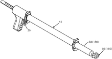
- FIG. 1 is an isometric view of an extensible adhesive dispensing gun system
- FIG. 2 is an isometric view of a known cord guide tool
- FIG. 3 is a view of the adhesive dispensing gun system in FIG. 1 , with the cord guide tool in FIG. 2 coupled to an adhesive syringe at a distal or far end of the system;
- FIG. 4A is an isometric view of a first embodiment of a fiber guide tool device according to the invention.
- FIG. 4B is an isometric view of the fiber guide tool device in FIG. 4A , as taken from beneath the device;
- FIG. 5A shows a distal end of an adhesive syringe to which the guide tool device can be joined, according to the invention
- FIG. 5B shows the guide tool device when joined to the distal end of the syringe in FIG. 5A ;
- FIG. 6A is an isometric view of a second embodiment of a fiber guide tool device according to the invention.
- FIG. 6B is an isometric view of the fiber guide tool device in FIG. 6A , as taken from beneath the device;
- FIG. 7 is an enlarged, cross-sectional view of the guide tool device in FIGS. 6A and 6B , showing an axial through passage inside the device;
- FIG. 8A shows the second embodiment of the guide tool device aligned with an adhesive dispensing nozzle at the distal end of the syringe in FIG. 5A , according to the invention
- FIG. 8B shows the guide tool device and the nozzle in FIG. 8A when operatively joined to one another
- FIG. 9 shows the syringe in FIG. 5A mounted at the distal end of the adhesive dispensing gun system in FIG. 1 , with either embodiment of the guide tool device operatively joined to the syringe;
- FIG. 10 shows a clip for retaining a fiber supply spool at a proximal end of the dispensing gun system shown in FIG. 9 ;
- FIG. 11 shows the clip in FIG. 10 mounted on the dispensing gun system in FIG. 9 , with a fiber supply spool retained for rotation about the clip;
- FIG. 12 illustrates the path of a fiber from the supply spool when the system in FIG. 11 deposits an adhesive with the fiber along a routing path at a user premises;
- FIG. 13 is an enlarged view showing the path of the fiber through the guide tool device in FIG. 12 .
- the fiber when a spooled 900 ⁇ m buffered fiber is unwound, the fiber typically exhibits some memory or set because the elastic limit of the buffer coating, which is often a polymeric material, was exceeded when the fiber was initially wound on the spool. That is, while the fiber is spooled, stresses are induced in the fiber windings which produce corresponding strains within the buffer coating. The stresses vary with the curvature of the windings, being greatest in the windings closest to the hub of the spool. Also, for any given winding, the maximum stress is at the outer circumference of the coating on the winding.
- the maximum stress induced in the buffer coating is reduced by 32.6% if the fiber is wound on a spool having a one-inch diameter hub.
- the maximum stress is reduced by at least 20% when the fiber is wound on a spool hub whose diameter is in the range of about 1.00 to 1.65 inches.
- Such decreases in the maximum stress will reduce the possibility that a small form factor buffered fiber will exhibit a permanent set when the fiber is unspooled.
- the reduced weight of a small form factor buffered fiber eliminates the need to apply tape over an installed length of the fiber until the adhesive in which the fiber is embedded cures, thus facilitating the overall installation process at the premises and saving valuable time.
- a small form factor fiber addresses issues related to supply spool density or capacity.
- installers arrive at a given premises, they usually do not know the exact dimensions or layout of the premises through which the fiber is to be routed, and where related components such as fiber storage modules and ONTs will be placed. It is therefore important to have enough fiber available for the installers to finish the installation regardless of the premises floor plan, while minimizing the volume needed to store any fiber that remains on the supply spool when the installation is complete.
- the capacity of a supply spool is determined by the radius of the spool hub, the width of the hub, and the height of the spool flanges at the axial ends of the hub.
- the geometry of the spool is constrained, however, by the space available within a given storage module, and the optical characteristics of the fiber, namely, its bend-loss performance.
- low-profile modules such as those available from OFS Fitel, LLC, and known as InvisiLight 80 ⁇ 80 modules, are used.
- Reducing the outer diameter of the fiber 900 ⁇ m to 600 ⁇ m will therefore more than double the capacity of a given supply spool, and allow a longer length of the fiber to be deployed on a low-profile spool that can be stored inside the mentioned 80 ⁇ 80 or other low-profile module.
- Yet another advantage of using of a small form factor buffered fiber is that the reduced diameter of the fiber makes it less visible than standard 900 ⁇ m fiber when installed. The reduced visibility will result in a more aesthetically pleasing installation.
- a small form factor buffered fiber for example, the commercially available 600 ⁇ m O.D. fiber identified above, is embedded and retained in an adhesive while the adhesive is being deposited over a desired path inside a user premises, without a need for a ladder.
- the installation is performed using either one of two fiber guide tool devices 50 , 150 which are shown in FIGS. 4 to 13 of the present application and described below.
- the tool devices 50 , 150 are constructed and arranged to deposit the adhesive over the desired path while simultaneously embedding the fiber in the adhesive. As a result, the time required to finish an aesthetically pleasing fiber installation at the premises is substantially reduced.
- guide tool device 50 is integrally formed, for example and without limitation, by injection molding of Nylon 6, polypropylene, or an equivalent thermoplastic material.
- the tool device 50 includes an elongated central body 52 having a generally rectangular cross section, and an elongated adhesive passage 54 is formed in the body between a proximal end 56 and a flat distal end 60 of the body 52 .
- the passage 54 is configured to communicate an adhesive that is supplied through a cylindrical boss 62 extending axially from the proximal end 56 , to an exit opening 58 on the flat distal end 60 of the body 52 .
- a conventional Luer-lock connector 64 is fixed on the open end of the boss 62 .
- the connector 64 is configured to attach the tool device 50 to a mating Luer connector 78 that is provided at a distal end of a syringe 80 such as shown in FIG. 5A and which is filled with a desired adhesive.
- the syringe 80 is commercially available with Luer connector 78 from, e.g., Nordson EFD.
- FIG. 5B shows the tool device 50 attached to the distal end of the syringe 80 .
- the guide tool device 50 also has a pair of fiber guide channels 64 a, 64 b extending from opposite sides of the central body 52 of the device, wherein each channel is inclined at an angle of approximately 43 degrees from the horizontal. Distal edges 66 a, 66 b of the channels 64 a, 64 b are adjacent to corresponding side edges of the flat distal end 60 of the body 52 , and the channel edges 66 a, 66 b are preferably rounded at a radius of, e.g., 0.05 inch.
- the tool device 50 when an optical fiber is aligned inside one of the channels 64 a, 64 b after a free end of the fiber is anchored at a given point along an installation path, and the tool device 50 is swept from the anchor point in the direction of the path, the fiber is guided through the channel for relative movement over the opening 58 of the adhesive passage 54 in flat distal end 60 of the device body 52 . See FIGS. 12 and 13 . It will also be understood that by constructing the two fiber guide channels 64 a, 64 b in opposed relation to one another along the central body 52 , the tool device 50 can be used to route a fiber in either direction along an installation path without having to remove and reposition the device along the path.
- Guide tool device 50 further includes a pair of fiber retaining lugs 68 a, 68 b extending from opposite sides of the central body 52 , below the fiber guide channels 64 a, 64 b.
- Each lug 68 a, 68 b has an opening 70 a, 70 b aligned beneath a corresponding one of the fiber guide channels 64 a, 64 b for passing an optical fiber from, e.g., a supply spool, to enter the corresponding guide channel while the tool device 50 is being used.
- the wall of each retaining lug 68 a, 68 b has an axial slot at 72 a, 72 b through which a fiber can be urged sideways into the lug opening.
- FIGS. 6A and 6B show another embodiment of a fiber guide tool device 150 according to the invention.
- Guide tool device 150 is constructed and arranged for attachment onto a commercially available dispensing nozzle 172 having a Luer-lock connector at the base of the nozzle, after the nozzle 172 is connected to the mating connector at the distal end of the syringe 180 . See FIGS. 8A and 8B .
- FIG. 7 is a cross-sectional view of the guide tool device 150 .
- the central body 152 of the tool device 150 has an adhesive thru passage 154 the diameter of which is tapered to narrow from the proximal end 156 of the body 152 to the exit opening 158 in flat distal end 160 of the body.
- the passage 154 is configured so that the tip of the nozzle 172 can enter the passage 154 at the proximal end 156 of the tool device 150 , and the nozzle 172 is retained in sealing relationship (e.g., by friction) inside the passage 154 when the central body 152 is urged over the nozzle as depicted in FIGS. 8A and 8B .
- the central body 152 of the tool device 150 also has a number of parallel, axially directed keyways 174 surrounding the opening of the thru passage 154 at the proximal end 156 of the body 152 .
- the keyways 174 are located and sized to receive a corresponding number of keys or ribs 176 that are formed about the base of the dispensing nozzle 172 on the adhesive syringe 180 , as shown in FIG. 8A .
- the ribs 176 at the base of the nozzle are received in the keyways 174 and will prevent the tool device 150 from rotating freely about the nozzle, thereby facilitating proper alignment of the tool device 150 relative to a dispensing gun system in which the device 150 is deployed.
- an installer can deposit the adhesive with an embedded fiber along elevated structural corners between, e.g., adjacent walls, a wall and a ceiling, or a wall and a molding at a premises, without needing a ladder.
- the flat distal ends 60 , 160 of the central bodies 52 , 152 of the tool devices are sized and formed so that when urged against and swept along structural corners, the space formed between the distal ends and the corners is relatively small.
- the adhesive is dispensed out from the exit openings 58 , 158 at the distal ends 60 , 160 of the device bodies, the adhesive is coated onto the fiber within the confines of the small space between the distal ends and the corners along which the devices are swept.
- the fiber is embedded neatly and precisely within the adhesive at the same time the adhesive is deposited in the corners by the tool devices.
- FIG. 10 shows a generally C-shaped spool retention clip 200 having two pairs of spool retaining fingers 202 a, 202 b extending radially from opposite positions along the circumference of the clip.
- Each pair of fingers is sized to receive and support the hub of a fiber supply spool 194 (see FIGS. 11 and 12 ) while allowing the spool to rotate freely around its axis.
- One pair of fingers e.g., 202 a
- the opposing pair e.g., 202 b
- the clip 200 may be made of plastics or an equivalent resilient material so it can be opened and mounted firmly by friction on the circumference of the outer tube 14 of the dispensing gun system 10 , near the proximal end of the system 10 as shown in FIGS. 11 and 12 . That is, the inside diameter of the clip 200 is less than the outside diameter of the outer tube 14 of the system so that the clip 200 is restrained from movement relative to the tube 14 once the clip is placed as desired.
- FIG. 11 shows the spool retention clip 200 positioned on the outer tube 14 of the dispensing gun system 10 , with the fiber supply spool 194 conveniently attached.
- FIG. 12 illustrates the path (in dashed lines) of the fiber from the mounted spool 194 , through one of the guide channels 64 a, 64 b (or 164 a, 164 b ) of the tool device mounted at the far end of the dispensing gun system 10 , and along an elevated routing path while the tool device is swept along the path by an installer.
- FIG. 13 is an enlarged view of the guide tool device 50 (or 150 ) at the distal end of the adhesive syringe 80 (or 180 ) in FIG. 12 , showing the path taken by the fiber from the supply spool to the tool device as the tool device is being used.
- a small form factor fiber as defined herein and which is light enough to remain securely embedded within a previously deposited but yet uncured adhesive is preferred.
- the use of such fiber will avoid a situation wherein the weight of an uninstalled length of fiber left hanging from the end of a recently installed fiber, causes the installed fiber to peel away before the adhesive in which the fiber is embedded is fully cured. Uninstalled lengths of fiber are commonly left hanging if an installer must pause the installation process on account of, e.g., unplanned interruptions, restroom breaks, phone calls, and the like.
- the inventive fiber guide tool devices 50 , 150 operate to deposit an adhesive over a defined routing path at a user premises including exposed elevated corners that would ordinarily require a ladder to reach, while at the same time embedding a supplied fiber in the adhesive.
- the fiber is guided over an opening in a flat distal end of the body of the device, so that the fiber is coated with the adhesive which is dispensed out of the opening.
- the flat distal end of the device body works to deposit the dispensed adhesive in the corner together with the fiber which is embedded in the adhesive.
- Excess adhesive is also accumulated and removed by the flat distal ends 60 , 160 of the tool devices, thereby depositing a straight and neat adhesive strip in which the fiber becomes firmly embedded when the adhesive cures. Because fewer if any ladder moves are required, the overall time needed to install an optical fiber when using either one of the tool devices 50 , 150 is significantly reduced.
Landscapes
- Engineering & Computer Science (AREA)
- Physics & Mathematics (AREA)
- Mechanical Engineering (AREA)
- General Physics & Mathematics (AREA)
- Optics & Photonics (AREA)
- Civil Engineering (AREA)
- Structural Engineering (AREA)
- Coating Apparatus (AREA)
Abstract
Description
- The present application claims priority under 35 U.S.C. § 119(e) of Provisional Patent Application No. 62/816,506 filed Mar. 11, 2019, titled Tool Device and Method for Installing Small-Form-Factor Fibers at User Premises, the entire contents of which are incorporated by reference.
- This application is also a continuation-in-part (CIP) under 35 U.S.C. § 120 of copending U.S. patent application Ser. No. 16/366,541 filed Mar. 27, 2019, and titled Installation of Small Form Factor Fibers at User Premises.
- The present invention concerns methods and tools for routing and installing an optical fiber inside the premises of fiber optic network users.
- Desktop optical network terminals (ONTs) are being deployed at an increasing rate inside the premises of fiber optic network users. ONTs are usually placed on a desk or shelf inside the premises near a TV set top box, cable modem, or other electronic device to which the ONT is connected so it can interface the device with the network.
- As used herein, the term premises means a home, an office, an apartment, or other living unit where a user of a fiber optic network resides and uses services provided by the network, e.g., Internet access, telephony, television, voice and music broadcasts, and/or other information and data streams that require the routing and installation of one or more optical fibers inside the premises. Also, the terms fiber, optical fiber, and cord are used interchangeably herein to connote an optical fiber that is buffered and/or jacketed, as well as a fiber optic cable that contains one or more optical fibers.
- Moreover, the term small form factor fiber as used herein refers to a fiber having an outside diameter (O.D.) between approximately 400 μm and 700 μm. For example, a 20 meter length of spooled 600 μm O.D. buffered fiber, suitable for installation at user premises as described herein, is commercially available from OFS Fitel, LLC, as part No. 301147609.
- Conventional staples can be used to secure a fiber to a wall, a wall molding, or other exposed and accessible structural surfaces at a premises, to minimize installation time and incur relatively low cost. Many users reject stapled installations, however, and opt instead for special moldings or conduits to conceal the fiber at their premises. Staples can also physically damage walls and moldings, and impair or break a fiber if not properly installed. Some users also prefer to hide all wires and fibers completely at their premises, thereby incurring expensive hardware with increased installation time.
- Accordingly, a procedure that enables an installer to route and bond an optical fiber quickly, properly, and safely along structural surfaces, grooves, and/or corners inside user premises with little if any visibility, is very desirable. A solution offered by OFS Fitel, LLC, under the registered mark InvisiLight fulfills this need by providing fast, easy, and virtually invisible fiber installations using a consumer grade, low odor, nonhazardous, water based adhesive to bond optical fibers to walls and ceilings indoors. Water based adhesives are preferred since they are typically non-toxic, allow clean up with soap and water, and can be shipped worldwide without restriction. As demand for InvisiLight installations has spread, users have expressed a desire that the installation time be reduced even more by addressing the following concerns.
- Currently, an installer must move and climb a ladder multiple times. First, he or she deposits an adhesive bead over successive elevated portions of the routing path by repositioning and climbing the ladder to reach the ceiling or molding at each portion, while at the same time holding onto an adhesive dispensing gun. To deposit the adhesive bead, the installer squeezes the gun trigger one or more times to cause a plunger inside the syringe to urge the adhesive out of an applicator nozzle.
- Once the adhesive bead is deposited over the entire routing path, the installer repeats the first series of ladder movements, climbing the ladder again at each elevated portion of the path where the installer manually presses the fiber into the bead. At many premises, however, large furniture (e.g., sofas and entertainment centers) are located directly beneath elevated portions of the routing path, thus making it difficult for the installer to use the ladder safely at such locations.
-
FIG. 1 shows an extensible adhesive dispensing gun system that is disclosed in U.S. Patent Application Pub. No. 2018/0345313 (Dec. 6, 2018), and which application is assigned to the present applicant. The system enables an installer to apply an adhesive bead along ceilings and crown moldings while standing on the floor at the premises. The system includes anadhesive dispensing gun 12, anouter extension tube 14, aninner rod 16 extending axially inside theextension tube 14 with a plunger head at a distal end of therod 16, asyringe adapter 18 at a distal end of theextension tube 14, and asyringe 20 having apiston 22 for dispensing an adhesive out of asyringe nozzle 24. - To apply an adhesive bead, the installer squeezes a
trigger 26 on thegun 12 one or more times to cause aplunger 28 in the gun to advance against theinner rod 16 which, in turn, urges thepiston 22 inside thesyringe 20 to dispense the adhesive out of thenozzle 24. A plunger head at the end of therod 16 applies uniform forward and outward pressure to a thin-walled, trailing end of the piston, 22 which helps to seal the piston against the inner wall of thesyringe 20, thus ensuring a reliable and consistent application of an adhesive bead from thenozzle 24. -
FIG. 2 shows a knowncord guide tool 40 that is shown inFIG. 10 of U.S. Patent Application Pub. No. 2018/0348465 (Dec. 6, 2018), and which application is also assigned to the present applicant. As seen inFIG. 3 of the present application, when attached to a distal end of thesyringe 20 in the extensibledispensing gun system 10 inFIG. 1 , theguide tool 40 enables an installer to embed a fiber neatly and precisely into the adhesive deposited by thesystem 10 near a ceiling without a ladder. Theguide tool 40 has a flat leadingedge 42 sized so that when urged across a corner between, e.g., adjacent walls, a wall and a ceiling, or a wall and a molding, the space formed between the leadingedge 42 and the corner is relatively small. While the adhesive is being deposited along the corner and a fiber is oriented to pass between the leadingedge 42 of theguide tool 40 and the corner, the guide tool embeds the fiber in the adhesive. - U.S. Pat. No. 9,835,817 (Dec. 5, 2017), also assigned to the present applicant and incorporated herein by reference, describes a tool for embedding an optical fiber in an adhesive that has been deposited along a structural corner in a building room or hallway, without a ladder. The patented tool has a trough for receiving and containing a fiber, a guide channel at a downstream end of the trough arranged to retain the fiber, and a nose at a downstream end of the channel for embedding the fiber in the adhesive when an installer uses a pole to sweep the tool nose over and against the adhesive.
- To facilitate an even faster installation while minimizing ladder use, several problems need to be solved. First, an extensible adhesive dispensing gun system like the
system 10 inFIG. 1 is required to eliminate the need for a ladder during adhesive application. Also required is a device that allows the fiber to be positioned along the routing path at the same time the adhesive is being deposited, thereby eliminating the need for an installer to traverse the routing path twice (i.e., first to deposit the adhesive, and again to embed the fiber in the adhesive). Finally, a small form factor fiber is needed that is light enough to stay embedded in an uncured adhesive deposit, and which will not peel out of the deposit when the weight of an adjacent length of the fiber is left to hang freely to the floor before it is installed. - For example, an uninstalled length of fiber may be left hanging if the installer pauses before completing an installation due to unplanned interruptions such as, e.g., restroom breaks, phone calls, and the like. A typical floor-to-ceiling height in a user premises is eight feet. On average, the weight of a conventional 900 μm O.D. buffered fiber which is often used in fiber installations at user premises, is 6.2×10⁻⁴ lb/ft. This can result in a downward peel force of approximately 0.005 lb being applied by a freely hanging uninstalled fiber, to the end of an adjacent length of fiber that is embedded in a yet uncured adhesive deposit. If the uncured adhesive cannot overcome the force, the embedded fiber will peel out of the adhesive unless secured by tape at one or more locations.
- According to one aspect of the invention, a guide tool device for an optical fiber or cord includes a central body having an adhesive passage formed between a proximal end and a flat distal end of the body. The passage is configured for communicating an adhesive supplied at the proximal end to an exit opening in the distal end of the body. A pair of fiber guide channels extend from opposite sides of the central body. Each channel is inclined so that a distal edge of the channel is adjacent a side edge of the distal end of the body, and the channel is formed to guide an optical fiber aligned inside the channel for relative movement over the exit opening of the passage in the distal end of the body during use of the device.
- A connector is fixed on the proximal end of the body in communication with the adhesive passage, and the connector is configured to mate with a connector at the distal end of a syringe containing the adhesive. Thus, when urged by the syringe, the adhesive flows through the passage and out the exit opening in the distal end of the body to coat the optical fiber when guided over the flat distal end during use.
- According to another aspect of the invention, a guide tool device for an optical fiber or cord includes a central body having an adhesive passage formed between a proximal end and a flat distal end of the body. The passage is configured for communicating an adhesive supplied at the proximal end to an exit opening in the distal end of the body. A pair of fiber guide channels extend from opposite sides of the central body. Each channel is inclined so that a distal edge of the channel is adjacent a side edge of the distal end of the body, and the channel is formed to guide an optical fiber aligned inside the channel for relative movement over the exit opening of the passage in the distal end of the body during use of the device.
- The diameter of the adhesive passage is tapered to narrow from the proximal end of the central body to the exit opening in the flat distal end of the body, so that a dispensing nozzle at a distal end of a syringe containing the adhesive is retained in sealing relationship inside the passage when the central body is urged over the nozzle. Thus, when urged by the syringe, the adhesive flows through the passage and out of the exit opening in the flat distal end of the body to coat the optical fiber when guided over the flat distal end during use of the tool device.
- For a better understanding of the invention, reference is made to the following description taken in conjunction with the accompanying drawing and the appended claims.
- In the drawing:
-
FIG. 1 is an isometric view of an extensible adhesive dispensing gun system; -
FIG. 2 is an isometric view of a known cord guide tool; -
FIG. 3 is a view of the adhesive dispensing gun system inFIG. 1 , with the cord guide tool inFIG. 2 coupled to an adhesive syringe at a distal or far end of the system; -
FIG. 4A is an isometric view of a first embodiment of a fiber guide tool device according to the invention; -
FIG. 4B is an isometric view of the fiber guide tool device inFIG. 4A , as taken from beneath the device; -
FIG. 5A shows a distal end of an adhesive syringe to which the guide tool device can be joined, according to the invention; -
FIG. 5B shows the guide tool device when joined to the distal end of the syringe inFIG. 5A ; -
FIG. 6A is an isometric view of a second embodiment of a fiber guide tool device according to the invention; -
FIG. 6B is an isometric view of the fiber guide tool device inFIG. 6A , as taken from beneath the device; -
FIG. 7 is an enlarged, cross-sectional view of the guide tool device inFIGS. 6A and 6B , showing an axial through passage inside the device; -
FIG. 8A shows the second embodiment of the guide tool device aligned with an adhesive dispensing nozzle at the distal end of the syringe inFIG. 5A , according to the invention; -
FIG. 8B shows the guide tool device and the nozzle inFIG. 8A when operatively joined to one another; -
FIG. 9 shows the syringe inFIG. 5A mounted at the distal end of the adhesive dispensing gun system inFIG. 1 , with either embodiment of the guide tool device operatively joined to the syringe; -
FIG. 10 shows a clip for retaining a fiber supply spool at a proximal end of the dispensing gun system shown inFIG. 9 ; -
FIG. 11 shows the clip inFIG. 10 mounted on the dispensing gun system inFIG. 9 , with a fiber supply spool retained for rotation about the clip; -
FIG. 12 illustrates the path of a fiber from the supply spool when the system inFIG. 11 deposits an adhesive with the fiber along a routing path at a user premises; and -
FIG. 13 is an enlarged view showing the path of the fiber through the guide tool device inFIG. 12 . - To address the earlier mentioned issues concerning installations of 900 μm O.D. buffered fiber in which the fiber is embedded in a deposited adhesive, it has been demonstrated that in addition to reduced weight per unit length of the fiber, the use of a small form factor fiber as defined herein will realize (i) improved resistance to acquiring a permanent set when the fiber is unspooled prior to or during installation, as explained below, and (ii) increased spool density, i.e., a longer length of the fiber can be supplied on a spool of a given size compared to 900 μm fiber.
- Specifically, when a spooled 900 μm buffered fiber is unwound, the fiber typically exhibits some memory or set because the elastic limit of the buffer coating, which is often a polymeric material, was exceeded when the fiber was initially wound on the spool. That is, while the fiber is spooled, stresses are induced in the fiber windings which produce corresponding strains within the buffer coating. The stresses vary with the curvature of the windings, being greatest in the windings closest to the hub of the spool. Also, for any given winding, the maximum stress is at the outer circumference of the coating on the winding.
- It can be shown that by reducing the outside diameter of a buffered fiber from 900 μm to 600 μm, the maximum stress induced in the buffer coating is reduced by 32.6% if the fiber is wound on a spool having a one-inch diameter hub. Moreover, for a buffered fiber having an O.D. ranging from approximately 400 μm to 700 μm, the maximum stress is reduced by at least 20% when the fiber is wound on a spool hub whose diameter is in the range of about 1.00 to 1.65 inches. Such decreases in the maximum stress will reduce the possibility that a small form factor buffered fiber will exhibit a permanent set when the fiber is unspooled. Also, as discussed earlier, the reduced weight of a small form factor buffered fiber eliminates the need to apply tape over an installed length of the fiber until the adhesive in which the fiber is embedded cures, thus facilitating the overall installation process at the premises and saving valuable time.
- Moreover, a small form factor fiber addresses issues related to supply spool density or capacity. When installers arrive at a given premises, they usually do not know the exact dimensions or layout of the premises through which the fiber is to be routed, and where related components such as fiber storage modules and ONTs will be placed. It is therefore important to have enough fiber available for the installers to finish the installation regardless of the premises floor plan, while minimizing the volume needed to store any fiber that remains on the supply spool when the installation is complete.
- For a given fiber diameter, the capacity of a supply spool is determined by the radius of the spool hub, the width of the hub, and the height of the spool flanges at the axial ends of the hub. The geometry of the spool is constrained, however, by the space available within a given storage module, and the optical characteristics of the fiber, namely, its bend-loss performance. To ensure optimal aesthetics, low-profile modules such as those available from OFS Fitel, LLC, and known as InvisiLight 80×80 modules, are used. Reducing the outer diameter of the fiber 900 μm to 600 μm will therefore more than double the capacity of a given supply spool, and allow a longer length of the fiber to be deployed on a low-profile spool that can be stored inside the mentioned 80×80 or other low-profile module.
- Yet another advantage of using of a small form factor buffered fiber is that the reduced diameter of the fiber makes it less visible than standard 900 μm fiber when installed. The reduced visibility will result in a more aesthetically pleasing installation.
- In accordance with the invention, a small form factor buffered fiber, for example, the commercially available 600 μm O.D. fiber identified above, is embedded and retained in an adhesive while the adhesive is being deposited over a desired path inside a user premises, without a need for a ladder. The installation is performed using either one of two fiber
guide tool devices FIGS. 4 to 13 of the present application and described below. Thetool devices - In a first embodiment illustrated in
FIGS. 4A and 4B ,guide tool device 50 is integrally formed, for example and without limitation, by injection molding of Nylon 6, polypropylene, or an equivalent thermoplastic material. Thetool device 50 includes an elongatedcentral body 52 having a generally rectangular cross section, and anelongated adhesive passage 54 is formed in the body between aproximal end 56 and a flatdistal end 60 of thebody 52. Thepassage 54 is configured to communicate an adhesive that is supplied through a cylindrical boss 62 extending axially from theproximal end 56, to anexit opening 58 on the flatdistal end 60 of thebody 52. - A conventional Luer-
lock connector 64 is fixed on the open end of the boss 62. Theconnector 64 is configured to attach thetool device 50 to amating Luer connector 78 that is provided at a distal end of asyringe 80 such as shown inFIG. 5A and which is filled with a desired adhesive. Thesyringe 80 is commercially available withLuer connector 78 from, e.g., Nordson EFD.FIG. 5B shows thetool device 50 attached to the distal end of thesyringe 80. - The
guide tool device 50 also has a pair offiber guide channels central body 52 of the device, wherein each channel is inclined at an angle of approximately 43 degrees from the horizontal. Distal edges 66 a, 66 b of thechannels distal end 60 of thebody 52, and the channel edges 66 a, 66 b are preferably rounded at a radius of, e.g., 0.05 inch. Accordingly, when an optical fiber is aligned inside one of thechannels tool device 50 is swept from the anchor point in the direction of the path, the fiber is guided through the channel for relative movement over the opening 58 of theadhesive passage 54 in flatdistal end 60 of thedevice body 52. SeeFIGS. 12 and 13 . It will also be understood that by constructing the twofiber guide channels central body 52, thetool device 50 can be used to route a fiber in either direction along an installation path without having to remove and reposition the device along the path. -
Guide tool device 50 further includes a pair of fiber retaining lugs 68 a, 68 b extending from opposite sides of thecentral body 52, below thefiber guide channels lug opening 70 a, 70 b aligned beneath a corresponding one of thefiber guide channels tool device 50 is being used. The wall of each retaininglug slot tool device 50. -
- Typical dimensions for the fiber
guide tool device 50 are, without limitation: - Width between outside ends of retaining
lugs - Height including boss 62: 1.3 inches.
- Height between
proximal end 56 and flatdistal end 60 of the device (excluding boss 62): 1.0 inch. - Width of flat
distal end 60 of the device: 0.11 inch. - Length of flat
distal end 60 of the device: 0.3 inch
- Typical dimensions for the fiber
-
FIGS. 6A and 6B show another embodiment of a fiberguide tool device 150 according to the invention. Features of thetool device 150 that correspond to those of thetool device 50 described above, have corresponding reference numbers increased by 100. -
Guide tool device 150 is constructed and arranged for attachment onto a commercially available dispensing nozzle 172 having a Luer-lock connector at the base of the nozzle, after the nozzle 172 is connected to the mating connector at the distal end of thesyringe 180. SeeFIGS. 8A and 8B . -
FIG. 7 is a cross-sectional view of theguide tool device 150. Thecentral body 152 of thetool device 150 has an adhesive thrupassage 154 the diameter of which is tapered to narrow from theproximal end 156 of thebody 152 to theexit opening 158 in flatdistal end 160 of the body. In particular, thepassage 154 is configured so that the tip of the nozzle 172 can enter thepassage 154 at theproximal end 156 of thetool device 150, and the nozzle 172 is retained in sealing relationship (e.g., by friction) inside thepassage 154 when thecentral body 152 is urged over the nozzle as depicted inFIGS. 8A and 8B . - The
central body 152 of thetool device 150 also has a number of parallel, axially directedkeyways 174 surrounding the opening of the thrupassage 154 at theproximal end 156 of thebody 152. Thekeyways 174 are located and sized to receive a corresponding number of keys orribs 176 that are formed about the base of the dispensing nozzle 172 on theadhesive syringe 180, as shown inFIG. 8A . Accordingly, when thecentral body 152 of thetool device 150 is urged over the nozzle 172, theribs 176 at the base of the nozzle are received in thekeyways 174 and will prevent thetool device 150 from rotating freely about the nozzle, thereby facilitating proper alignment of thetool device 150 relative to a dispensing gun system in which thedevice 150 is deployed. - When either one of the
guide tool devices adhesive syringe gun system 10 as shown inFIG. 9 , an installer can deposit the adhesive with an embedded fiber along elevated structural corners between, e.g., adjacent walls, a wall and a ceiling, or a wall and a molding at a premises, without needing a ladder. - Specifically, the flat distal ends 60, 160 of the
central bodies exit openings -
FIG. 10 shows a generally C-shapedspool retention clip 200 having two pairs ofspool retaining fingers FIGS. 11 and 12 ) while allowing the spool to rotate freely around its axis. One pair of fingers (e.g., 202 a) is sized for a low-profile supply spool, and the opposing pair (e.g., 202 b) is sized for larger, high-capacity supply spools. Theclip 200 may be made of plastics or an equivalent resilient material so it can be opened and mounted firmly by friction on the circumference of theouter tube 14 of the dispensinggun system 10, near the proximal end of thesystem 10 as shown inFIGS. 11 and 12 . That is, the inside diameter of theclip 200 is less than the outside diameter of theouter tube 14 of the system so that theclip 200 is restrained from movement relative to thetube 14 once the clip is placed as desired. -
FIG. 11 shows thespool retention clip 200 positioned on theouter tube 14 of the dispensinggun system 10, with thefiber supply spool 194 conveniently attached.FIG. 12 illustrates the path (in dashed lines) of the fiber from the mountedspool 194, through one of theguide channels gun system 10, and along an elevated routing path while the tool device is swept along the path by an installer.FIG. 13 is an enlarged view of the guide tool device 50 (or 150) at the distal end of the adhesive syringe 80 (or 180) inFIG. 12 , showing the path taken by the fiber from the supply spool to the tool device as the tool device is being used. - As mentioned earlier, in order for the inventive tool device 50 (or 150) to work reliably, a small form factor fiber as defined herein and which is light enough to remain securely embedded within a previously deposited but yet uncured adhesive, is preferred. The use of such fiber will avoid a situation wherein the weight of an uninstalled length of fiber left hanging from the end of a recently installed fiber, causes the installed fiber to peel away before the adhesive in which the fiber is embedded is fully cured. Uninstalled lengths of fiber are commonly left hanging if an installer must pause the installation process on account of, e.g., unplanned interruptions, restroom breaks, phone calls, and the like.
- An example of a procedure for installing a supplied fiber along an elevated routing path using the
guide tool device 50, is described below. Steps listed below are intended to be exemplary only, and not to limit the scope of the invention. - 1. If present, remove a cap from the distal end of the
adhesive syringe 80 when mounted at the far end of the adhesivedispensing gun system 10 inFIG. 11 . - 2. Attach the tool device to the distal end of the
adhesive syringe 80 by twisting Luer-lock connector 64 at the proximal end of the device into the mating connector on the syringe. - 3. Place the
spool retention clip 200 on the dispensinggun system 10, and mount thefiber supply spool 194 for rotation on the retention clip. - 4. Unspool enough length of fiber to establish an anchor point at a desired starting position along the routing path at the premises, and fasten an end of the fiber to the anchor point using tape.
- 5. Place the unspooled length of fiber into the fiber guide channel (64 a or 64 b) that faces in the direction in which the
tool device 50 will be swept inFIGS. 12 and 13 . Then gently slide the tool device upward along the fiber until the tool device is at the anchor point. - 6. Position the
tool device 50 as needed to ensure the flatdistal end 60 on the body of the device maintains contact with the structural corner along which the distal end will be swept. - 7. Pull the
trigger 26 of the dispensinggun system 10 slowly and repeatedly as needed to dispense the adhesive out from theopening 58 in thedistal end 60 of the device body to coat the fiber, while sweeping thetool device 50 along the routing path to deposit the adhesive while simultaneously embedding the fiber in the adhesive. - An example of a procedure for installing a supplied fiber along an elevated routing path using the
guide tool device 150, is described below. Steps listed below are intended to be exemplary only, and not to limit the scope of the invention. - 1. If present, remove a cap from the distal end of the
adhesive syringe 180 when mounted at the far end of the adhesivedispensing gun system 10 inFIG. 11 . - 2. Attach the nozzle 172 to the distal end of the
syringe 180 by twisting the connector at the base of the nozzle into the mating connector on the syringe. - 3. Attach the
guide tool device 150 to theadhesive syringe 180 by aligning thekeyways 174 in the proximal end of thedevice 150, with thekeys 176 at the base of the syringe nozzle 172, and press fit thetool device 150 over the nozzle. - 4. Place the
spool retention clip 200 on the dispensinggun system 10, and mount the fiber supply spool for rotation on the retention clip. - 5. Unspool enough fiber to establish an anchor point at a desired starting point along the routing path.
- 6. Place the unspooled length of fiber into the fiber guide channel (164 a or 164 b) that faces in the direction in which the
tool device 150 will be swept inFIGS. 12 and 13 . Then gently slide the tool device upward along the fiber until the tool device is at the anchor point. - 7. Position the
tool device 150 as needed to ensure the flatdistal end 160 on the body of the device maintains contact with the structural corner along which the distal end will be swept. - 8. Pull the
trigger 26 of the dispensinggun system 10 slowly and repeatedly as needed to dispense the adhesive out from theopening 158 in thedistal end 160 of the device body to coat the fiber, while sweeping thetool device 150 along the routing path to deposit the adhesive while simultaneously embedding the fiber in the adhesive. - As disclosed herein, the inventive fiber
guide tool devices - Excess adhesive is also accumulated and removed by the flat distal ends 60, 160 of the tool devices, thereby depositing a straight and neat adhesive strip in which the fiber becomes firmly embedded when the adhesive cures. Because fewer if any ladder moves are required, the overall time needed to install an optical fiber when using either one of the
tool devices - While the foregoing represents preferred embodiments of the present invention, it will be understood by persons skilled in the art that various changes, modifications, and additions can be made without departing from the spirit and scope of the invention, and that the invention includes all such changes, modifications, and additions that are within the scope of the following claims.
Claims (20)
Priority Applications (1)
| Application Number | Priority Date | Filing Date | Title |
|---|---|---|---|
| US16/432,270 US10816747B2 (en) | 2019-03-11 | 2019-06-05 | Installation of small form factor fibers at user premises |
Applications Claiming Priority (3)
| Application Number | Priority Date | Filing Date | Title |
|---|---|---|---|
| US201962816506P | 2019-03-11 | 2019-03-11 | |
| US16/366,541 US10935749B2 (en) | 2018-11-20 | 2019-03-27 | Installation of small form factor fibers at user premises |
| US16/432,270 US10816747B2 (en) | 2019-03-11 | 2019-06-05 | Installation of small form factor fibers at user premises |
Related Parent Applications (1)
| Application Number | Title | Priority Date | Filing Date |
|---|---|---|---|
| US16/366,541 Continuation-In-Part US10935749B2 (en) | 2018-11-20 | 2019-03-27 | Installation of small form factor fibers at user premises |
Publications (2)
| Publication Number | Publication Date |
|---|---|
| US20200292774A1 true US20200292774A1 (en) | 2020-09-17 |
| US10816747B2 US10816747B2 (en) | 2020-10-27 |
Family
ID=72424074
Family Applications (1)
| Application Number | Title | Priority Date | Filing Date |
|---|---|---|---|
| US16/432,270 Active US10816747B2 (en) | 2019-03-11 | 2019-06-05 | Installation of small form factor fibers at user premises |
Country Status (1)
| Country | Link |
|---|---|
| US (1) | US10816747B2 (en) |
Cited By (3)
| Publication number | Priority date | Publication date | Assignee | Title |
|---|---|---|---|---|
| EP4080169A1 (en) * | 2021-04-20 | 2022-10-26 | Palo Alto Research Center Incorporated | Optical fiber installation tool |
| US11668889B2 (en) | 2021-04-20 | 2023-06-06 | Palo Alto Research Center Incorporated | System for applying pre-strain to an optical sensor |
| US12306443B2 (en) | 2021-08-23 | 2025-05-20 | Xerox Corporation | Optical fiber attachment device |
Family Cites Families (4)
| Publication number | Priority date | Publication date | Assignee | Title |
|---|---|---|---|---|
| US10259006B2 (en) * | 2017-05-30 | 2019-04-16 | Ofs Fitel, Llc | Extensible adhesive dispensing gun system |
| US10746951B2 (en) * | 2017-05-30 | 2020-08-18 | Ofs Fitel, Llc | Tool device for installing optical fibers at user premises |
| US10302887B1 (en) * | 2017-12-11 | 2019-05-28 | Ofs Fitel, Llc | Optical cord retaining device |
| US10935749B2 (en) * | 2018-11-20 | 2021-03-02 | Ofs Fitel, Llc | Installation of small form factor fibers at user premises |
-
2019
- 2019-06-05 US US16/432,270 patent/US10816747B2/en active Active
Cited By (4)
| Publication number | Priority date | Publication date | Assignee | Title |
|---|---|---|---|---|
| EP4080169A1 (en) * | 2021-04-20 | 2022-10-26 | Palo Alto Research Center Incorporated | Optical fiber installation tool |
| US11668889B2 (en) | 2021-04-20 | 2023-06-06 | Palo Alto Research Center Incorporated | System for applying pre-strain to an optical sensor |
| US12449282B2 (en) | 2021-04-20 | 2025-10-21 | Xerox Corporation | System for applying pre-strain to an optical sensor |
| US12306443B2 (en) | 2021-08-23 | 2025-05-20 | Xerox Corporation | Optical fiber attachment device |
Also Published As
| Publication number | Publication date |
|---|---|
| US10816747B2 (en) | 2020-10-27 |
Similar Documents
| Publication | Publication Date | Title |
|---|---|---|
| EP2567271B1 (en) | Optical fiber installation at customer premises | |
| US10816747B2 (en) | Installation of small form factor fibers at user premises | |
| US20130020015A1 (en) | Apparatus and Methods for Routing an Optical Fiber or Cable Inside a Building or Living Unit | |
| US8792766B2 (en) | Tool for routing an optical fiber or cable at a living unit of customer premises | |
| US8842960B2 (en) | Ducts to support a drop access location system for horizontal cabling in multi-dwelling unit applications | |
| EP3657225B1 (en) | INSTALLATION OF LOW SHARP FIBERS IN USER'S FACILITIES | |
| US10746951B2 (en) | Tool device for installing optical fibers at user premises | |
| JP6766085B2 (en) | Laying fiber optic bundles in apartment buildings to provide network access to multiple user dwellings | |
| EP2304485A2 (en) | Drop access location method and system for horizontal cabling in multi-dwelling unit applications | |
| US9874712B2 (en) | Module for optical fiber installation and storage at customer premises | |
| US9835817B2 (en) | Tool for installing an optical fiber in a building room or hallway | |
| EP3495864B1 (en) | Optical cord retaining device | |
| JP5258936B2 (en) | Tools for laying optical fiber or cables in residential areas of customer buildings | |
| EP3924763B1 (en) | Optical fiber and adhesive dispenser system |
Legal Events
| Date | Code | Title | Description |
|---|---|---|---|
| FEPP | Fee payment procedure |
Free format text: ENTITY STATUS SET TO UNDISCOUNTED (ORIGINAL EVENT CODE: BIG.); ENTITY STATUS OF PATENT OWNER: LARGE ENTITY |
|
| AS | Assignment |
Owner name: OFS FITEL, LLC, GEORGIA Free format text: ASSIGNMENT OF ASSIGNORS INTEREST;ASSIGNORS:BRADLEY, KELVIN B;CHIRON, XAVIER;SIGNING DATES FROM 20190606 TO 20200724;REEL/FRAME:053849/0239 |
|
| STCF | Information on status: patent grant |
Free format text: PATENTED CASE |
|
| MAFP | Maintenance fee payment |
Free format text: PAYMENT OF MAINTENANCE FEE, 4TH YEAR, LARGE ENTITY (ORIGINAL EVENT CODE: M1551); ENTITY STATUS OF PATENT OWNER: LARGE ENTITY Year of fee payment: 4 |