US20180339736A1 - Modular Beam Hauler - Google Patents
Modular Beam Hauler Download PDFInfo
- Publication number
- US20180339736A1 US20180339736A1 US15/983,673 US201815983673A US2018339736A1 US 20180339736 A1 US20180339736 A1 US 20180339736A1 US 201815983673 A US201815983673 A US 201815983673A US 2018339736 A1 US2018339736 A1 US 2018339736A1
- Authority
- US
- United States
- Prior art keywords
- trailer
- module
- axle
- axles
- frame
- Prior art date
- Legal status (The legal status is an assumption and is not a legal conclusion. Google has not performed a legal analysis and makes no representation as to the accuracy of the status listed.)
- Granted
Links
- 230000000694 effects Effects 0.000 claims abstract description 15
- 238000010276 construction Methods 0.000 description 2
- 238000004891 communication Methods 0.000 description 1
- 230000006835 compression Effects 0.000 description 1
- 238000007906 compression Methods 0.000 description 1
- 230000003247 decreasing effect Effects 0.000 description 1
- 239000012530 fluid Substances 0.000 description 1
- 238000000034 method Methods 0.000 description 1
- 238000012986 modification Methods 0.000 description 1
- 230000004048 modification Effects 0.000 description 1
- 239000011435 rock Substances 0.000 description 1
Images


Classifications
-
- B—PERFORMING OPERATIONS; TRANSPORTING
- B62—LAND VEHICLES FOR TRAVELLING OTHERWISE THAN ON RAILS
- B62D—MOTOR VEHICLES; TRAILERS
- B62D53/00—Tractor-trailer combinations; Road trains
- B62D53/005—Combinations with at least three axles and comprising two or more articulated parts
-
- B—PERFORMING OPERATIONS; TRANSPORTING
- B60—VEHICLES IN GENERAL
- B60P—VEHICLES ADAPTED FOR LOAD TRANSPORTATION OR TO TRANSPORT, TO CARRY, OR TO COMPRISE SPECIAL LOADS OR OBJECTS
- B60P3/00—Vehicles adapted to transport, to carry or to comprise special loads or objects
- B60P3/40—Vehicles adapted to transport, to carry or to comprise special loads or objects for carrying long loads, e.g. with separate wheeled load supporting elements
-
- B—PERFORMING OPERATIONS; TRANSPORTING
- B62—LAND VEHICLES FOR TRAVELLING OTHERWISE THAN ON RAILS
- B62D—MOTOR VEHICLES; TRAILERS
- B62D13/00—Steering specially adapted for trailers
- B62D13/04—Steering specially adapted for trailers for individually-pivoted wheels
-
- B—PERFORMING OPERATIONS; TRANSPORTING
- B62—LAND VEHICLES FOR TRAVELLING OTHERWISE THAN ON RAILS
- B62D—MOTOR VEHICLES; TRAILERS
- B62D63/00—Motor vehicles or trailers not otherwise provided for
- B62D63/06—Trailers
- B62D63/068—Trailers with more than two axles or more than four wheels
Definitions
- the present invention relates to a modular trailer including a steering device for steering the modular trailer, as well as a module of the modular trailer and a towing system including the modular trailer.
- Trailers are attachable to cabs to haul loads of various shapes and sizes. At times, the load to be carried is quite long. Sometimes, the load is too long for any single trailer unit to haul. Examples of such loads include long beams, such as long I-beams or beams used in the construction of bridges and other infrastructure. To carry these difficult loads, a towing system that includes a first trailer attached to a cab and a second trailer remote from the cab may be used, with the load spanning both the first and second trailer.
- Certain towing systems use a second trailer that is not modular but formed as a single unit. Such second trailers are not sufficiently maneuverable and cannot be separated into modules.
- the steering system is not optimally maneuverable. For each module, all of the axles turn on a single block and cannot be turned individually. This leads to decreased maneuverability of the towing system and the inability to turn the axles while the towing system is stationary. Thus, even the modular second trailers in these towing systems can be difficult to steer when carrying large loads, making transportation of the load more difficult, time consuming, and expensive.
- the present invention is directed to a modular trailer including: a front module including a frame, a plurality of axles connected to the frame, and a plurality of wheels connected to each axle; a rear module including a frame, a plurality of axles connected to the frame, and a plurality of wheels connected to each axle; a center module including a frame having a front end and a rear end, the front end removably pinned to the front module and the rear end removably pinned to the rear module, the center module further including a bearing rotatable relative to the frame; and a steering device operatively associated with the bearing and co-acting with at least one of the axles such that rotation of the bearing effects turning of the at least one axle.
- the present invention is also directed to a towing system including: a cab; at least one trailer; and a load received by the at least one trailer.
- the at least one trailer includes: a front module including a frame, a plurality of axles connected to the frame, and a plurality of wheels connected to each axle; a rear module including a frame, a plurality of axles connected to the frame, and a plurality of wheels connected to each axle; a center module including a frame having a front end and a rear end, the front end removably pinned to the front module and the rear end removably pinned to the rear module, the center module further including a bearing rotatable relative to the frame; and a steering device operatively associated with the bearing and co-acting with at least one of the axles such that rotation of the bearing effects turning of the at least one axle.
- the present invention is also directed to a module of a modular trailer including: a frame; a plurality of axles connected to the frame; a plurality of wheels connected to each axle; and a power unit.
- Each axle of the plurality of axles is configured to turn individually relative to the frame, and the power unit is configured to cause each of the axles to turn.
- FIG. 1A shows a side view of a 3-axle dolly
- FIG. 1B shows a side view of a 4-axle dolly
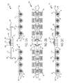
- FIG. 2A shows a side view of a disassembled 8-axle trailer
- FIG. 2B shows a plan view of the assembled trailer of FIG. 2A ;
- FIG. 2C shows a side view of the assembled trailer of FIG. 2A ;
- FIG. 3A shows a side view of a 6-axle trailer
- FIG. 3B shows a side view of an 8-axle trailer
- FIG. 4A shows a perspective view of a 6-axle trailer
- FIG. 4B shows a perspective view of an 8-axle trailer
- FIG. 5A shows a perspective view of a front 3-axle dolly
- FIG. 5B shows a perspective view of a front 4-axle dolly
- FIG. 5C shows a perspective view of a rear 3-axle dolly
- FIG. 5D shows a perspective view of a rear 4-axle dolly
- FIG. 6A shows a side view of a towing system used for back hauling
- FIG. 6B shows a side view of a towing system for hauling a load spanning a trailer according to the present invention and a second trailer connected to a cab;
- FIG. 7 shows a perspective view of a towing system
- FIG. 8 shows a perspective view of a trailer
- FIG. 9A shows a ring bearing bell-crank steering arrangement used in a trailer according to the present invention.
- FIG. 9B shows the ring bearing bell-crank steering arrangement of FIG. 9A ;
- FIG. 9C shows the ring bearing bell-crank steering arrangement of FIG. 9A ;
- FIG. 9D shows the ring bearing bell-crank steering arrangement of FIG. 9A .
- any numerical range recited herein is intended to include all sub-ranges subsumed therein.
- a range of “1 to 10” is intended to include all sub-ranges between (and including) the recited minimum value of 1 and the recited maximum value of 10, that is, having a minimum value equal to or greater than 1 and a maximum value of equal to or less than 10.
- the dolly 10 may include a frame 12 configured for supporting a load.
- the frame 12 may be a flatbed configured for towing.
- the dolly 10 may include a plurality of axles 14 connected to the frame 12 , and each axle 14 may be connected to a plurality of wheels 16 .
- the axles 14 may be turning or non-turning axles.
- the axles 14 may turn individually and in combination relative to the frame 12 .
- the dolly 10 may include three axles 14 (see FIG. 1A ) or four axles 14 (see FIG.
- the dolly 10 may have any number of axles 14 sufficient for allowing the dolly 10 to drive on a road towing a load.
- the dolly 10 may include an individual turntable 18 connected to each individual axle 14 so that each axles 14 may turn independently of the other axles relative to the frame.
- the turntable 18 may be disposed between the axle 14 and the frame 12 .
- the turntable 18 may be configured to turn the axle 14 relative to the frame 12 by rotation of the turntable 18 .
- the dolly 10 may also include a platform 20 connected to the frame 12 .
- the platform 20 may be configured to receive a load 22 and secure the load 22 to the frame 12 for towing.
- the platform 20 may include a lift box (not shown), which allows the height of the platform 20 to be adjusted vertically, so that the distance of the platform from the frame 12 may be adjusted.
- the dolly 10 may be connected to a cab (not shown) to haul various loads 22 .
- the dolly 10 may be used by itself as a trailer to haul the loads 22 , or the dolly 10 may be connected to other dollies 10 (as a module) to form a larger trailer to haul the loads 22 , as described herein.
- the dollies 10 described in FIGS. 1A-1B may be modules of a trailer 24 , which is larger than the individual dollies 10 to haul larger loads 22 .
- the trailer 24 may be configured to haul long beams, such as long I-beams or beams used in the construction of bridges and other infrastructure.
- the trailer 24 may be configured to carry other loads, large or small, or loads of an unusual shape.
- the trailer 24 includes a front module 26 , and a rear module 28 .
- the front module 26 and the rear module 28 include identical components and designs of the dollies 10 of FIGS. 1A and 1B .
- the front module 26 may be configured closer to a cab, when being used for hauling, than the rear module 28 .
- the front module 26 and rear module 28 may include a front pin receiver 30 and a rear pin receiver 32 , respectively. These pin receivers 30 , 32 may be configured to receive a pin or other attachment member so that other components can be connected to the front module 26 and rear module 28 .
- the front module 26 and the rear module 28 may further include a receiving hole 41 for receiving a pin.
- the trailer 24 may also include a center module 34 .
- the center module 34 may include a center frame 35 configured for supporting a load 22 .
- the center module 34 may be connected to the front module 26 and the rear module 28 to form the trailer 28 .
- the center module 34 may include a front end 36 disposed near the front module 26 when the center module 34 is connected to the front module 26 and the rear module 28 to form the trailer 24 .
- the center module may include a rear end 38 disposed near the rear module 28 when the center module 34 is connected to the front module 26 and the rear module 28 to form the trailer 24 .
- the front module 26 and the rear module 28 may each be the three or four axle dollies from FIGS. 1A and 1B to form a six or eight axle trailer 24 .
- dollies with different numbers of axles 14 may be used to form a trailer 24 with the number of axles 14 being sufficient for allowing the trailer 24 to drive on a road towing a load 22 .
- the center module 34 may include a front pin 40 and a rear pin 42 .
- the front pin 40 may be received by the front pin receiver 30 and then fastened to the front pin receiver 30 using any fastening means, such as a screw or bolt.
- the front pin 40 may be removably received by the front pin receiver 30 such that the center module 34 may be pinned and detached from the front module 26 any number of times over the life of these components. This allows the trailer 24 to be made longer when needed or disassembled when it is not necessary to haul a large load 22 .
- the rear pin 42 may be received by the rear pin receiver 32 and then fastened to the rear pin receiver 32 using any fastening means, such as a screw or bolt.
- the rear pin 42 may be removably received by the rear pin receiver 32 such that the center module 34 may be pinned and detached from the rear module 28 any number of times over the life of these components. This allows the trailer 24 to be made longer, when needed or disassembled when it is not necessary to haul a large load 22 .
- the front pin 40 and rear pin 42 may be received by the front pin receiver 30 and rear pin receiver 32 , respectively, such that the front pin 40 and rear pin 42 can rock back and forth during transportation to allow for increased maneuverability of the trailer 24 .
- the front end 36 of the center module 34 may be pinned in line with an axle 14 of the front module 26
- the rear end 38 of the center module 34 may be pinned in line with an axle 14 of the rear module 28
- the front pin receiver 30 and the rear pin receiver 32 may be positioned directly over an axle 14 such that the front pin 40 and rear pin 42 , when inserted into the pin receivers 30 , 32 , are positioned directly over an axle 14
- the pinning may not be in line with an axle 14 .
- the center module 34 may further include at least one center pin 43 , which may co-act with the receiving holes 41 of the front module 26 and the rear module 28 to provide a more rigid connection of the front module 26 , the rear module 28 , and the center module 34 .
- the center module 34 may be connected to the front module 26 and rear module 28 using any other pin arrangement 50 that is sufficient to securely connect the center module 34 to the front module 26 and the rear module 28 .
- the center module 34 may be pinned to the front module 26 and the rear module 28 such that the pinned center module 34 , front module 26 , and rear module 28 together form a rigid frame unit to form the trailer 24 .
- a rigid frame unit means that the center module 34 , front module 26 , and rear module 28 are securely connected so as to move as a single unit and stably support a load 22 placed thereon. The connection may be tight between the components so that they do no move independently from one another but move as the rigid frame unit.
- the center module 34 may include a bearing 44 , which in some non-limiting embodiments may be a ring bearing 44 .
- the ring bearing 44 may be disposed within the frame 35 of the center module.
- the ring bearing 44 may be arranged in the center (lengthwise) of the center module 34 such that it is proximate the center (lengthwise) of the assembled trailer 24 .
- the ring bearing 44 may be rotatable relative to the center frame 35 .
- the ring bearing 44 may be circular.
- the platform 20 may be connected to the ring bearing 44 to receive the load 22 , such as connected to the center of the ring bearing 44 .
- the platform 20 may be configured to receive a beam for towing.
- the platform 20 may be any other shape depending on the load 22 .
- the platform 20 may be adjustable depending on the shape of the load.
- the platform 20 may include adjustable walls 21 a , 21 b , which may be moved toward or away from each other in order to clamp against the load (not shown). It will be appreciated that the platform 20 may include other adjustable arrangements capable of securing the load to the platform 20 .
- a steering device may be operatively associated with the ring bearing 44 and co-acting with at least one of the axles 14 such that rotation of the ring bearing 44 effects turning of the at least one axle 14 .
- the steering device includes a bellcrank 48 connected to the ring bearing 44 .
- the steering device includes a sensor 49 configured to sense a degree of rotation of the ring bearing 44 .
- a clip 46 may be connected to the ring bearing 44 .
- the clip 46 may be connected to the ring bearing 44 proximate the edge of the ring bearing 44 .
- the clip 46 may be arranged at the edge of the ring bearing 44 proximate the rear module 28 when the components are connected to form the trailer 24 .
- the clip 46 is arranged at the edge of the ring bearing 44 proximate the front module 26 when the components are connected to form the trailer 24 .
- the clip 46 may be connected to a bellcrank 48 .
- a ring bearing 44 -bellcrank 48 steering arrangement used in one non-limiting embodiment of the trailer 24 is shown.
- the clip 46 may be connected to the bellcrank 48 on one end.
- the other end of the bellcrank 48 may be connected to a plurality of sensing cylinders 52 .
- the sensing cylinders 52 may be connected to the bellcrank on one end 48 and to the frame 35 on the other end.
- the sensing cylinders 52 may also be connected to a steering cylinder 53 by a hose (not shown), which allows oil from the sensing cylinders 52 to be in fluid communication with the steering cylinder 53
- the steering cylinder 53 may be connected to at least one of the turntables 18 .
- the steering cylinder 53 may be positioned on the front module 26 and/or the rear module 28 .
- rotation of the ring bearing 44 may cause the clip 46 to rotate with the ring bearing 44 .
- Movement of the clip 46 causes movement of the bellcrank 48 which causes expansion or compression of the sensing cylinders 52 .
- Movement of the sensing cylinders 52 causes oil from the steering cylinders 52 to be displaced to/from the steering cylinder 53 , which, in turn, causes rotation of the turntable 18 co-acting with the at least one axle 14 , and rotation of the turntable 18 causes the at least one axle 14 to turn, which turns the wheels 16 attached thereto.
- the steering cylinder 53 is attached to the turntable 18 of the axle 14 closest to the bellcrank 48 .
- the steering cylinder 53 is attached to the turntable 18 of the axle 14 farthest to the bellcrank 48 (see FIGS. 3A-4B ).
- the steering arrangement is shown arranged on the rear module 28 .
- the bellcrank 48 and sensing cylinders 52 co-act with the steering cylinder 53 , a turntable 18 , and an axle 14 of the rear module 28 .
- the steering arrangement may be on the front module 26 , with the bellcrank 48 and sensing cylinders 52 co-acting with the steering cylinder 53 , a turntable 18 , and an axle 14 of the front module 26 .
- FIG. 4A as an illustration of this example, the left side of FIG. 4A may be proximate the front (closer to the cab) while the right side of FIG. 4A may be proximate the back (away from the cab), and the platform 20 may support the end portion of the beam.
- a left turn by the cab may pull the beam to the left (towards the bottom of FIG. 4A ), which effects a counter clockwise rotation of the ring bearing 44 .
- the clip 46 may rotate with the ring bearing 44 in the counter clockwise direction, which, transferring the motion through the bellcrank 48 , may cause the sensing cylinders 52 to expand or compress to displace oil to/from the steering cylinder 53 , which co-acts with the turntable 18 to cause the turntable 18 to rotate in the clockwise direction.
- the clockwise rotation of the turntable 18 may turn the axles 14 and wheels 16 of the rear module 28 to the right (towards the top of FIG. 4A ).
- a left turn of the cab may cause the wheels 16 of the rear module 28 to turn to the right to aid the trailer 24 in turning, based on the steering arrangement described.
- a right turn by the cab may pull the beam to the right (towards the top of FIG.
- the clip 46 may rotate with the ring bearing 44 in the clockwise direction, which transferring the motion through the bellcrank 48 , may cause the sensing cylinders 52 to expand or compress to displace oil to/from the steering cylinder 53 , which co-acts with the turntable to cause the turntable 18 to rotate in the counter-clockwise direction.
- the counter clockwise rotation of the turntable 18 may turn the axles 14 and wheels 16 of the rear module 28 to the left (towards the bottom of FIG. 4A ).
- a right turn of the cab may cause the wheels 16 of the rear module 28 to turn to the left to aid the trailer 24 in turning, based on the steering arrangement described.
- the wheels 16 of the front module 26 may be steered (instead of the wheels 16 of the rear module) in a similar way when the ring bearing 44 is connected to and co-acts with the axles 14 of the front module 26 .
- the ring bearing 44 -bellcrank 48 steering arrangement may further include a rod 54 connecting each turntable 18 to an adjacent turntable 18 .
- a rod 54 may be positioned between each adjacent turntable 18 to connect adjacent turntables 18 to each other.
- the adjacent turntables 18 may be connected to one another using a single rod 54 or a plurality of rods 54 .
- the rods 54 are configured to rotate a turntable when the adjacent turntable 18 is rotated.
- the turntable 18 connected to the steering cylinder 53 is connected to the steering cylinder 53 on one end and connected to the rod 54 on the other end to connect the turntable 18 closest to the steering cylinder 53 to its adjacent turntable 18 .
- the steering cylinder 53 may cause rotation of the turntable 18 to which they are connected (because of the rotation of the ring bearing 44 ), which may cause rotation of the adjacent turntable 18 by the rod 54 .
- rotation of the ring bearing 44 may cause the rotation of the turntable 18 closest thereto (to turn the axle 14 ), which causes the rotation of downline turntables 18 in that module connected to one another via rods 54 (to turn the remaining of the plurality of axles 14 in that module, e.g., the rear module 26 or the front module 26 ).
- the connection between the adjacent turntables 18 may be some other member other than the rod 54 which causes the adjacent turntables 18 to co-act with one another upon rotation of one of the turntables 18 .
- each axle 14 co-acts individually with its own turntable 18 such that each axle 14 may turn individually, and the adjacent turntables 18 may co-act with adjacent turntables 18 such that turning of one turntable 18 may turn the adjacent turntable.
- the axles 14 are capable of turning individually and in combination with one another.
- the above-described ring bearing 44 -bellcrank 48 steering arrangement describes steering of the trailer 24 in automatic mode, and automatic mode does not require a power unit to operate.
- the trailer 24 may be alternatively driven in a manual mode. Manual mode may bypass the sensing cylinders 52 to steer the trailer 24 .
- the trailer 24 may include at least one power unit 56 to steer the trailer 24 in manual mode.
- the power unit 56 may be configured to allow a steersman to manually turn at least one axle 14 via the turntables 18 (thus turning the wheels 16 ) of the front module 26 and/or the rear module 28 .
- the power unit 56 may allow for each axle 14 of the front module 26 and/or rear module 28 to be turned manually (relative to the frames 12 ) and may allow for a single axle 14 or any combination of the axles 14 of the front module 26 and/or rear module 28 to be turned manually.
- the plurality of axles 14 in the trailer 24 may turn in manual mode while the trailer 24 is stationary. This may allow for more precise control over the turning of the trailer 24 , which may be useful for particularly tight or otherwise difficult turns.
- the power unit 56 may turn the axle(s) 14 manually when the trailer 24 is stationary (before beginning movement). This may allow the trailer 24 to begin a turn immediately when starting movement from a stationary position.
- the power unit 56 may cause oil to be displaced to/from the steering cylinder 53 such that the steering cylinder 53 may suitably co-act with the turntable 18 to turn the axle 14 .
- any combination of automatic mode and manual mode maybe used for the front module 26 and the rear module 28 of a trailer 24 .
- the front and rear module 26 , 28 of the trailer 24 may both be steered in automatic mode and manual mode.
- the front module 26 may be steered in manual mode, while the rear module 28 may be steered in manual mode and/or automatic mode.
- the front module 26 may be steered in manual mode and/or automatic mode, while the rear module 28 may be steered in manual mode.
- the trailer 24 may include the sensor 49 as the steering device as opposed to the bellcrank 48 .
- the sensor 49 may be operatively connected to the ring bearing 44 and sense the degree and direction the ring bearing 44 rotation (because of the turning of the cab and load 22 ).
- the sensor 49 may communicate (e.g., wirelessly or through a wired connection) with the power unit 56 , which causes oil to be displaced to/from the steering cylinder 53 to effect rotation of the axles 14 .
- the sensor 49 may determine the amount of oil to displace to/from the steering cylinder 53 to determine the degree to which the axles 14 rotate based on the degree and direction of rotation of the ring bearing 44 sensed by the sensor 49 .
- FIGS. 5A-5D various additional non-limiting examples of the dolly 10 are shown.
- FIG. 5A shows a perspective view of a front 3-axle dolly 10 .
- FIG. 5B shows a perspective view of a front 4-axle dolly 10 .
- FIG. 5C shows a perspective view of a rear 3-axle dolly 10 .
- FIG. 5D shows a perspective view of a rear 4-axle dolly 10 .
- the dollies 10 shown in FIGS. 5A-5D may be used as a module in the modular trailer 24 including a previously described center module 34 to connect the front dolly to the rear dolly.
- the dollies 10 shown in FIGS. 5A-5D may be directly connected by themselves to a cab or second trailer to be backhauled.
- a dolly 10 from FIG. 5A-5D may be used as a trailer to haul a load 22 without being used as part of the modular trailer 24 described herein.
- a back end of a load 22 may be placed on the dolly 10 with the front end of the load placed on a second trailer attached to a cab or to the cab itself (such as to the fifth wheel of the cab) to tow the load 22 .
- the 10 dolly may not be attached to the cab or the second trailer except for by the load 22 received by dolly 10 and the cab or second trailer.
- the frame 12 of the dolly 10 may stay in-line with the load 22 spanning between the dolly 10 and the cab or second trailer during a turn, and the axles 14 may turn to steer the dolly 10 .
- the dollies 10 may include a power unit 56 to steer the axles 14 of the dollies 10 .
- the power unit 56 may steer each axle 14 of the dollies 10 individually, with each axle 14 being individually mounted on its own turntable 18 .
- the power unit 56 may cause oil to be displaced to/from the steering cylinder 53 to cause the steering cylinder 53 to co-act with the turntable 18 to turn the axle 14 .
- the towing system 58 may include a cab 60 , which may be a motorized vehicle configured to tow a load 22 .
- the towing system 58 may also include a front trailer 62 (also referred to herein as a “second trailer”), and the front trailer 62 may be connected to the cab 60 .
- the front trailer 62 may be configured to haul a load 22 .
- the front trailer 62 may include a platform 20 to receive the load 22 .
- the towing system 58 may also include a rear trailer 24 , which is the trailer 24 of the present invention as described above.
- the front trailer 62 may co-act with the rear trailer 24 to haul a load 22 spanning both the front trailer 62 and the rear trailer 24 .
- the front trailer 62 is optional, and the front end of the load 22 may be instead received by the cab 60 , such as at the fifth wheel of the cab 60 to haul a load 22 spanning both the cab 60 and the rear trailer 24 .
- the towing system 58 may be used for backhauling the rear trailer 24 .
- a tie bar 64 may connect the front trailer 62 or cab 60 and the rear trailer 24 to keep the towing system 58 together during backhauling of the rear trailer 24 .
- the tie bar 64 may be connected to one of the axles 14 and/or the turntables 18 of the rear trailer 24
- the towing system 58 may include a load 22 having a front portion and a rear portion, the front portion may be received by the front trailer 62 or cab 60 and the rear portion received by the rear trailer 24 .
- the load 22 may be a long beam, for example.
- the beam may be secured to the front trailer 62 or cab 60 and rear trailer 24 using the fasteners 66 .
- the rear trailer 24 may not be connected to the front trailer 62 or cab 60 except by the load 22 received by the front trailer 62 or cab 60 and the rear trailer 24 .
- FIG. 7 a non-limiting example of the towing system 58 of the present invention hauling a load 22 is shown.
- FIG. 7 shows the towing system 58 in transit and making a turn.
- This illustrated example shows the towing system 58 without the tie bar 64 such that the load 22 holds the front trailer 62 and the rear trailer 24 together.
- FIG. 8 a non-limiting embodiment of the trailer 24 is shown.
- the trailer 24 includes the power unit 56 for effecting a manual mode for driving the trailer 24 .
- FIG. 8 shows the trailer 24 with the axles 14 and wheels 16 turned so that the trailer 24 may make a right turn.
- the axles 14 and wheels 16 of the front module 26 are turned to the right, and the axles 14 and wheels 16 of the rear module 28 are turned to the left.
- FIGS. 9A-9D various views of the above-described ring bearing 44 -bellcrank 48 steering arrangement are shown.
- the ring bearing 44 includes a clip 46 to which the bellcrank 48 is connected.
- two sensing cylinders 52 Connected to the opposite side of the bellcrank 48 are two sensing cylinders 52 configured to effect rotation of the axles 14 (as previously described) upon rotation of the ring bearing 44 .
Landscapes
- Engineering & Computer Science (AREA)
- Transportation (AREA)
- Mechanical Engineering (AREA)
- Chemical & Material Sciences (AREA)
- Combustion & Propulsion (AREA)
- Health & Medical Sciences (AREA)
- Public Health (AREA)
- Steering-Linkage Mechanisms And Four-Wheel Steering (AREA)
Abstract
Description
- This application claims priority to U.S. Provisional Patent Application No. 62/511,689, filed on May 26, 2017, the disclosure of which is hereby incorporated in its entirety by reference.
- The present invention relates to a modular trailer including a steering device for steering the modular trailer, as well as a module of the modular trailer and a towing system including the modular trailer.
- Trailers are attachable to cabs to haul loads of various shapes and sizes. At times, the load to be carried is quite long. Sometimes, the load is too long for any single trailer unit to haul. Examples of such loads include long beams, such as long I-beams or beams used in the construction of bridges and other infrastructure. To carry these difficult loads, a towing system that includes a first trailer attached to a cab and a second trailer remote from the cab may be used, with the load spanning both the first and second trailer.
- Certain towing systems use a second trailer that is not modular but formed as a single unit. Such second trailers are not sufficiently maneuverable and cannot be separated into modules.
- In commercially available towing systems that do include modularity, the steering system is not optimally maneuverable. For each module, all of the axles turn on a single block and cannot be turned individually. This leads to decreased maneuverability of the towing system and the inability to turn the axles while the towing system is stationary. Thus, even the modular second trailers in these towing systems can be difficult to steer when carrying large loads, making transportation of the load more difficult, time consuming, and expensive.
- The present invention is directed to a modular trailer including: a front module including a frame, a plurality of axles connected to the frame, and a plurality of wheels connected to each axle; a rear module including a frame, a plurality of axles connected to the frame, and a plurality of wheels connected to each axle; a center module including a frame having a front end and a rear end, the front end removably pinned to the front module and the rear end removably pinned to the rear module, the center module further including a bearing rotatable relative to the frame; and a steering device operatively associated with the bearing and co-acting with at least one of the axles such that rotation of the bearing effects turning of the at least one axle.
- The present invention is also directed to a towing system including: a cab; at least one trailer; and a load received by the at least one trailer. The at least one trailer includes: a front module including a frame, a plurality of axles connected to the frame, and a plurality of wheels connected to each axle; a rear module including a frame, a plurality of axles connected to the frame, and a plurality of wheels connected to each axle; a center module including a frame having a front end and a rear end, the front end removably pinned to the front module and the rear end removably pinned to the rear module, the center module further including a bearing rotatable relative to the frame; and a steering device operatively associated with the bearing and co-acting with at least one of the axles such that rotation of the bearing effects turning of the at least one axle.
- The present invention is also directed to a module of a modular trailer including: a frame; a plurality of axles connected to the frame; a plurality of wheels connected to each axle; and a power unit. Each axle of the plurality of axles is configured to turn individually relative to the frame, and the power unit is configured to cause each of the axles to turn.
-
FIG. 1A shows a side view of a 3-axle dolly; -
FIG. 1B shows a side view of a 4-axle dolly; -
FIG. 2A shows a side view of a disassembled 8-axle trailer; -
FIG. 2B shows a plan view of the assembled trailer ofFIG. 2A ; -
FIG. 2C shows a side view of the assembled trailer ofFIG. 2A ; -
FIG. 3A shows a side view of a 6-axle trailer; -
FIG. 3B shows a side view of an 8-axle trailer; -
FIG. 4A shows a perspective view of a 6-axle trailer; -
FIG. 4B shows a perspective view of an 8-axle trailer; -
FIG. 5A shows a perspective view of a front 3-axle dolly; -
FIG. 5B shows a perspective view of a front 4-axle dolly; -
FIG. 5C shows a perspective view of a rear 3-axle dolly; -
FIG. 5D shows a perspective view of a rear 4-axle dolly; -
FIG. 6A shows a side view of a towing system used for back hauling; -
FIG. 6B shows a side view of a towing system for hauling a load spanning a trailer according to the present invention and a second trailer connected to a cab; -
FIG. 7 shows a perspective view of a towing system; -
FIG. 8 shows a perspective view of a trailer; -
FIG. 9A shows a ring bearing bell-crank steering arrangement used in a trailer according to the present invention; -
FIG. 9B shows the ring bearing bell-crank steering arrangement ofFIG. 9A ; -
FIG. 9C shows the ring bearing bell-crank steering arrangement ofFIG. 9A ; and -
FIG. 9D shows the ring bearing bell-crank steering arrangement ofFIG. 9A . - For the purpose of the following detailed description, it is to be understood that the invention may assume various alternative variations and step sequences, except where expressly specified to the contrary. Moreover, other than in any operating examples, or where otherwise indicated, all numbers used in the specification and claims are to be understood as being modified in all instances by the term “about”. Accordingly, unless indicated to the contrary, the numerical parameters set forth in the following specification and attached claims are approximations that may vary depending upon the desired properties to be obtained by the present invention. At the very least, and not as an attempt to limit the application of the doctrine of equivalents to the scope of the claims, each numerical parameter should at least be construed in light of the number of reported significant digits and by applying ordinary rounding techniques.
- Also, it should be understood that any numerical range recited herein is intended to include all sub-ranges subsumed therein. For example, a range of “1 to 10” is intended to include all sub-ranges between (and including) the recited minimum value of 1 and the recited maximum value of 10, that is, having a minimum value equal to or greater than 1 and a maximum value of equal to or less than 10.
- Referring to
FIGS. 1A and 1B , non-limiting embodiments of adolly 10 are shown. Thedolly 10 may include aframe 12 configured for supporting a load. Theframe 12 may be a flatbed configured for towing. Thedolly 10 may include a plurality ofaxles 14 connected to theframe 12, and eachaxle 14 may be connected to a plurality ofwheels 16. Theaxles 14 may be turning or non-turning axles. Theaxles 14 may turn individually and in combination relative to theframe 12. In some non-limiting embodiments, thedolly 10 may include three axles 14 (seeFIG. 1A ) or four axles 14 (seeFIG. 1B ); however, it will be appreciated that thedolly 10 may have any number ofaxles 14 sufficient for allowing thedolly 10 to drive on a road towing a load. Thedolly 10 may include anindividual turntable 18 connected to eachindividual axle 14 so that each axles 14 may turn independently of the other axles relative to the frame. Theturntable 18 may be disposed between theaxle 14 and theframe 12. Theturntable 18 may be configured to turn theaxle 14 relative to theframe 12 by rotation of theturntable 18. Thedolly 10 may also include aplatform 20 connected to theframe 12. Theplatform 20 may be configured to receive aload 22 and secure theload 22 to theframe 12 for towing. Theplatform 20 may include a lift box (not shown), which allows the height of theplatform 20 to be adjusted vertically, so that the distance of the platform from theframe 12 may be adjusted. Thedolly 10 may be connected to a cab (not shown) to haul various loads 22. Thedolly 10 may be used by itself as a trailer to haul theloads 22, or thedolly 10 may be connected to other dollies 10 (as a module) to form a larger trailer to haul theloads 22, as described herein. - Referring to
FIGS. 2A-4B , thedollies 10 described inFIGS. 1A-1B may be modules of atrailer 24, which is larger than theindividual dollies 10 to haul larger loads 22. In some non-limiting embodiments, thetrailer 24 may be configured to haul long beams, such as long I-beams or beams used in the construction of bridges and other infrastructure. However, thetrailer 24 may be configured to carry other loads, large or small, or loads of an unusual shape. - With continued reference to
FIGS. 2A-4B , thetrailer 24 includes afront module 26, and arear module 28. In some non-limiting embodiments, thefront module 26 and therear module 28 include identical components and designs of thedollies 10 ofFIGS. 1A and 1B . Thefront module 26 may be configured closer to a cab, when being used for hauling, than therear module 28. Thefront module 26 andrear module 28 may include afront pin receiver 30 and arear pin receiver 32, respectively. Thesepin receivers front module 26 andrear module 28. Thefront module 26 and therear module 28 may further include a receivinghole 41 for receiving a pin. - The
trailer 24 may also include acenter module 34. Thecenter module 34 may include acenter frame 35 configured for supporting aload 22. Thecenter module 34 may be connected to thefront module 26 and therear module 28 to form thetrailer 28. Thecenter module 34 may include afront end 36 disposed near thefront module 26 when thecenter module 34 is connected to thefront module 26 and therear module 28 to form thetrailer 24. The center module may include arear end 38 disposed near therear module 28 when thecenter module 34 is connected to thefront module 26 and therear module 28 to form thetrailer 24. As shown inFIGS. 3A-4B , thefront module 26 and therear module 28 may each be the three or four axle dollies fromFIGS. 1A and 1B to form a six or eightaxle trailer 24. However, it will be appreciated that dollies with different numbers ofaxles 14 may be used to form atrailer 24 with the number ofaxles 14 being sufficient for allowing thetrailer 24 to drive on a road towing aload 22. - Referring to
FIG. 2A-2C , thecenter module 34 may include afront pin 40 and arear pin 42. To connect thecenter module 34 to thefront module 26, thefront pin 40 may be received by thefront pin receiver 30 and then fastened to thefront pin receiver 30 using any fastening means, such as a screw or bolt. Thefront pin 40 may be removably received by thefront pin receiver 30 such that thecenter module 34 may be pinned and detached from thefront module 26 any number of times over the life of these components. This allows thetrailer 24 to be made longer when needed or disassembled when it is not necessary to haul alarge load 22. To connect thecenter module 34 to therear module 28, therear pin 42 may be received by therear pin receiver 32 and then fastened to therear pin receiver 32 using any fastening means, such as a screw or bolt. Therear pin 42 may be removably received by therear pin receiver 32 such that thecenter module 34 may be pinned and detached from therear module 28 any number of times over the life of these components. This allows thetrailer 24 to be made longer, when needed or disassembled when it is not necessary to haul alarge load 22. Thefront pin 40 andrear pin 42 may be received by thefront pin receiver 30 andrear pin receiver 32, respectively, such that thefront pin 40 andrear pin 42 can rock back and forth during transportation to allow for increased maneuverability of thetrailer 24. - In some non-limiting embodiments, and as shown in
FIG. 2A-2C , thefront end 36 of thecenter module 34 may be pinned in line with anaxle 14 of thefront module 26, and therear end 38 of thecenter module 34 may be pinned in line with anaxle 14 of therear module 28. In other words, thefront pin receiver 30 and therear pin receiver 32 may be positioned directly over anaxle 14 such that thefront pin 40 andrear pin 42, when inserted into thepin receivers axle 14. However, in other non-limiting embodiments, the pinning may not be in line with anaxle 14. - The
center module 34 may further include at least onecenter pin 43, which may co-act with the receiving holes 41 of thefront module 26 and therear module 28 to provide a more rigid connection of thefront module 26, therear module 28, and thecenter module 34. - Referring to
FIGS. 3A and 3B , thecenter module 34 may be connected to thefront module 26 andrear module 28 using anyother pin arrangement 50 that is sufficient to securely connect thecenter module 34 to thefront module 26 and therear module 28. - Whether the
center module 34 is connected to thefront module 26 or therear module 28 using the configuration shown inFIGS. 2A-2C orFIGS. 3A and 3B or any other conceivable arrangement, thecenter module 34 may be pinned to thefront module 26 and therear module 28 such that the pinnedcenter module 34,front module 26, andrear module 28 together form a rigid frame unit to form thetrailer 24. A rigid frame unit means that thecenter module 34,front module 26, andrear module 28 are securely connected so as to move as a single unit and stably support aload 22 placed thereon. The connection may be tight between the components so that they do no move independently from one another but move as the rigid frame unit. - With continued reference to
FIGS. 2A-4B , thecenter module 34 may include abearing 44, which in some non-limiting embodiments may be aring bearing 44. Thering bearing 44 may be disposed within theframe 35 of the center module. In some non-limiting embodiments, the ring bearing 44 may be arranged in the center (lengthwise) of thecenter module 34 such that it is proximate the center (lengthwise) of the assembledtrailer 24. Thering bearing 44 may be rotatable relative to thecenter frame 35. Thering bearing 44 may be circular. - The
platform 20 may be connected to the ring bearing 44 to receive theload 22, such as connected to the center of thering bearing 44. Theplatform 20 may be configured to receive a beam for towing. Theplatform 20 may be any other shape depending on theload 22. In some non-limiting examples, theplatform 20 may be adjustable depending on the shape of the load. For example, as shown inFIGS. 4A-4B , theplatform 20 may includeadjustable walls platform 20 may include other adjustable arrangements capable of securing the load to theplatform 20. - A steering device may be operatively associated with the ring bearing 44 and co-acting with at least one of the
axles 14 such that rotation of the ring bearing 44 effects turning of the at least oneaxle 14. In some non-limiting examples, the steering device includes abellcrank 48 connected to thering bearing 44. In other non-limiting examples the steering device includes asensor 49 configured to sense a degree of rotation of thering bearing 44. - In the bellcrank arrangement, a
clip 46 may be connected to thering bearing 44. Theclip 46 may be connected to the ring bearing 44 proximate the edge of thering bearing 44. In some non-limiting embodiments, theclip 46 may be arranged at the edge of the ring bearing 44 proximate therear module 28 when the components are connected to form thetrailer 24. In some non-limiting embodiments, theclip 46 is arranged at the edge of the ring bearing 44 proximate thefront module 26 when the components are connected to form thetrailer 24. As shown inFIGS. 3A and 3B , theclip 46 may be connected to abellcrank 48. - Referring to
FIGS. 3A-4B , a ring bearing 44-bellcrank 48 steering arrangement used in one non-limiting embodiment of thetrailer 24 is shown. As previously described, theclip 46 may be connected to thebellcrank 48 on one end. In one non-limiting embodiment, the other end of thebellcrank 48 may be connected to a plurality ofsensing cylinders 52. Thesensing cylinders 52 may be connected to the bellcrank on oneend 48 and to theframe 35 on the other end. Thesensing cylinders 52 may also be connected to asteering cylinder 53 by a hose (not shown), which allows oil from thesensing cylinders 52 to be in fluid communication with thesteering cylinder 53 Thesteering cylinder 53 may be connected to at least one of theturntables 18. Thesteering cylinder 53 may be positioned on thefront module 26 and/or therear module 28. - To steer the
trailer 24, rotation of the ring bearing 44 may cause theclip 46 to rotate with thering bearing 44. Movement of theclip 46 causes movement of thebellcrank 48 which causes expansion or compression of thesensing cylinders 52. Movement of thesensing cylinders 52 causes oil from thesteering cylinders 52 to be displaced to/from thesteering cylinder 53, which, in turn, causes rotation of theturntable 18 co-acting with the at least oneaxle 14, and rotation of theturntable 18 causes the at least oneaxle 14 to turn, which turns thewheels 16 attached thereto. In some non-limiting embodiments, thesteering cylinder 53 is attached to theturntable 18 of theaxle 14 closest to thebellcrank 48. In some non-limiting embodiments, thesteering cylinder 53 is attached to theturntable 18 of theaxle 14 farthest to the bellcrank 48 (seeFIGS. 3A-4B ). In the non-limiting embodiments shown, the steering arrangement is shown arranged on therear module 28. In other words, thebellcrank 48 andsensing cylinders 52 co-act with thesteering cylinder 53, aturntable 18, and anaxle 14 of therear module 28. However, the steering arrangement may be on thefront module 26, with thebellcrank 48 andsensing cylinders 52 co-acting with thesteering cylinder 53, aturntable 18, and anaxle 14 of thefront module 26. - Using
FIG. 4A as an illustration of this example, the left side ofFIG. 4A may be proximate the front (closer to the cab) while the right side ofFIG. 4A may be proximate the back (away from the cab), and theplatform 20 may support the end portion of the beam. A left turn by the cab may pull the beam to the left (towards the bottom ofFIG. 4A ), which effects a counter clockwise rotation of thering bearing 44. Theclip 46 may rotate with the ring bearing 44 in the counter clockwise direction, which, transferring the motion through thebellcrank 48, may cause thesensing cylinders 52 to expand or compress to displace oil to/from thesteering cylinder 53, which co-acts with theturntable 18 to cause theturntable 18 to rotate in the clockwise direction. The clockwise rotation of theturntable 18 may turn theaxles 14 andwheels 16 of therear module 28 to the right (towards the top ofFIG. 4A ). Thus, a left turn of the cab may cause thewheels 16 of therear module 28 to turn to the right to aid thetrailer 24 in turning, based on the steering arrangement described. A right turn by the cab may pull the beam to the right (towards the top ofFIG. 4A ), which effects a clockwise rotation of thering bearing 44. Theclip 46 may rotate with the ring bearing 44 in the clockwise direction, which transferring the motion through thebellcrank 48, may cause thesensing cylinders 52 to expand or compress to displace oil to/from thesteering cylinder 53, which co-acts with the turntable to cause theturntable 18 to rotate in the counter-clockwise direction. The counter clockwise rotation of theturntable 18 may turn theaxles 14 andwheels 16 of therear module 28 to the left (towards the bottom ofFIG. 4A ). Thus, a right turn of the cab may cause thewheels 16 of therear module 28 to turn to the left to aid thetrailer 24 in turning, based on the steering arrangement described. It will be appreciated that thewheels 16 of thefront module 26 may be steered (instead of thewheels 16 of the rear module) in a similar way when the ring bearing 44 is connected to and co-acts with theaxles 14 of thefront module 26. - With continued reference to
FIGS. 3A-4B , in one non-limiting embodiment, the ring bearing 44-bellcrank 48 steering arrangement may further include arod 54 connecting eachturntable 18 to anadjacent turntable 18. In this way, arod 54 may be positioned between eachadjacent turntable 18 to connectadjacent turntables 18 to each other. Theadjacent turntables 18 may be connected to one another using asingle rod 54 or a plurality ofrods 54. Therods 54 are configured to rotate a turntable when theadjacent turntable 18 is rotated. In some non-limiting embodiments, theturntable 18 connected to thesteering cylinder 53 is connected to thesteering cylinder 53 on one end and connected to therod 54 on the other end to connect theturntable 18 closest to thesteering cylinder 53 to itsadjacent turntable 18. In this non-limiting embodiment, thesteering cylinder 53 may cause rotation of theturntable 18 to which they are connected (because of the rotation of the ring bearing 44), which may cause rotation of theadjacent turntable 18 by therod 54. Thus, rotation of the ring bearing 44 may cause the rotation of theturntable 18 closest thereto (to turn the axle 14), which causes the rotation ofdownline turntables 18 in that module connected to one another via rods 54 (to turn the remaining of the plurality ofaxles 14 in that module, e.g., therear module 26 or the front module 26). In some non-limiting embodiments, the connection between theadjacent turntables 18 may be some other member other than therod 54 which causes theadjacent turntables 18 to co-act with one another upon rotation of one of theturntables 18. Based on this description, eachaxle 14 co-acts individually with itsown turntable 18 such that eachaxle 14 may turn individually, and theadjacent turntables 18 may co-act withadjacent turntables 18 such that turning of oneturntable 18 may turn the adjacent turntable. In this way, theaxles 14 are capable of turning individually and in combination with one another. - The above-described ring bearing 44-
bellcrank 48 steering arrangement describes steering of thetrailer 24 in automatic mode, and automatic mode does not require a power unit to operate. Referring toFIGS. 3A-4B , thetrailer 24 may be alternatively driven in a manual mode. Manual mode may bypass thesensing cylinders 52 to steer thetrailer 24. Thetrailer 24 may include at least onepower unit 56 to steer thetrailer 24 in manual mode. Thepower unit 56 may be configured to allow a steersman to manually turn at least oneaxle 14 via the turntables 18 (thus turning the wheels 16) of thefront module 26 and/or therear module 28. Thepower unit 56 may allow for eachaxle 14 of thefront module 26 and/orrear module 28 to be turned manually (relative to the frames 12) and may allow for asingle axle 14 or any combination of theaxles 14 of thefront module 26 and/orrear module 28 to be turned manually. The plurality ofaxles 14 in thetrailer 24 may turn in manual mode while thetrailer 24 is stationary. This may allow for more precise control over the turning of thetrailer 24, which may be useful for particularly tight or otherwise difficult turns. In some non-limiting embodiments, thepower unit 56 may turn the axle(s) 14 manually when thetrailer 24 is stationary (before beginning movement). This may allow thetrailer 24 to begin a turn immediately when starting movement from a stationary position. In manual mode, thepower unit 56 may cause oil to be displaced to/from thesteering cylinder 53 such that thesteering cylinder 53 may suitably co-act with theturntable 18 to turn theaxle 14. - Any combination of automatic mode and manual mode maybe used for the
front module 26 and therear module 28 of atrailer 24. In one example, the front andrear module trailer 24 may both be steered in automatic mode and manual mode. In one example, thefront module 26 may be steered in manual mode, while therear module 28 may be steered in manual mode and/or automatic mode. In one example, thefront module 26 may be steered in manual mode and/or automatic mode, while therear module 28 may be steered in manual mode. - Referring back to
FIGS. 2A-2C , thetrailer 24 may include thesensor 49 as the steering device as opposed to thebellcrank 48. Thesensor 49 may be operatively connected to the ring bearing 44 and sense the degree and direction the ring bearing 44 rotation (because of the turning of the cab and load 22). Thesensor 49 may communicate (e.g., wirelessly or through a wired connection) with thepower unit 56, which causes oil to be displaced to/from thesteering cylinder 53 to effect rotation of theaxles 14. Thesensor 49 may determine the amount of oil to displace to/from thesteering cylinder 53 to determine the degree to which theaxles 14 rotate based on the degree and direction of rotation of the ring bearing 44 sensed by thesensor 49. - Referring to
FIGS. 5A-5D , various additional non-limiting examples of thedolly 10 are shown.FIG. 5A shows a perspective view of a front 3-axle dolly 10.FIG. 5B shows a perspective view of a front 4-axle dolly 10.FIG. 5C shows a perspective view of a rear 3-axle dolly 10.FIG. 5D shows a perspective view of a rear 4-axle dolly 10. Thedollies 10 shown inFIGS. 5A-5D may be used as a module in themodular trailer 24 including a previously describedcenter module 34 to connect the front dolly to the rear dolly. - In some examples, the
dollies 10 shown inFIGS. 5A-5D may be directly connected by themselves to a cab or second trailer to be backhauled. In some non-limiting examples, adolly 10 fromFIG. 5A-5D may be used as a trailer to haul aload 22 without being used as part of themodular trailer 24 described herein. A back end of aload 22 may be placed on thedolly 10 with the front end of the load placed on a second trailer attached to a cab or to the cab itself (such as to the fifth wheel of the cab) to tow theload 22. The 10 dolly may not be attached to the cab or the second trailer except for by theload 22 received bydolly 10 and the cab or second trailer. Theframe 12 of thedolly 10 may stay in-line with theload 22 spanning between thedolly 10 and the cab or second trailer during a turn, and theaxles 14 may turn to steer thedolly 10. - The
dollies 10 may include apower unit 56 to steer theaxles 14 of thedollies 10. Thepower unit 56 may steer eachaxle 14 of thedollies 10 individually, with eachaxle 14 being individually mounted on itsown turntable 18. Thepower unit 56 may cause oil to be displaced to/from thesteering cylinder 53 to cause thesteering cylinder 53 to co-act with theturntable 18 to turn theaxle 14. - Referring to
FIGS. 6A and 6B , non-limiting embodiments of towingsystems 58 are shown. The towingsystem 58 may include acab 60, which may be a motorized vehicle configured to tow aload 22. The towingsystem 58 may also include a front trailer 62 (also referred to herein as a “second trailer”), and thefront trailer 62 may be connected to thecab 60. Thefront trailer 62 may be configured to haul aload 22. Thefront trailer 62 may include aplatform 20 to receive theload 22. The towingsystem 58 may also include arear trailer 24, which is thetrailer 24 of the present invention as described above. Thefront trailer 62 may co-act with therear trailer 24 to haul aload 22 spanning both thefront trailer 62 and therear trailer 24. In some non-limiting embodiments, thefront trailer 62 is optional, and the front end of theload 22 may be instead received by thecab 60, such as at the fifth wheel of thecab 60 to haul aload 22 spanning both thecab 60 and therear trailer 24. - Referring to
FIG. 6A , the towingsystem 58 may be used for backhauling therear trailer 24. Atie bar 64 may connect thefront trailer 62 orcab 60 and therear trailer 24 to keep the towingsystem 58 together during backhauling of therear trailer 24. Thetie bar 64 may be connected to one of theaxles 14 and/or theturntables 18 of therear trailer 24 - Referring to
FIG. 6B , the towingsystem 58 may include aload 22 having a front portion and a rear portion, the front portion may be received by thefront trailer 62 orcab 60 and the rear portion received by therear trailer 24. Theload 22 may be a long beam, for example. The beam may be secured to thefront trailer 62 orcab 60 andrear trailer 24 using thefasteners 66. Thus, therear trailer 24 may not be connected to thefront trailer 62 orcab 60 except by theload 22 received by thefront trailer 62 orcab 60 and therear trailer 24. - Referring to
FIG. 7 , a non-limiting example of the towingsystem 58 of the present invention hauling aload 22 is shown.FIG. 7 shows the towingsystem 58 in transit and making a turn. This illustrated example shows the towingsystem 58 without thetie bar 64 such that theload 22 holds thefront trailer 62 and therear trailer 24 together. - Referring to
FIG. 8 a non-limiting embodiment of thetrailer 24 is shown. Thetrailer 24 includes thepower unit 56 for effecting a manual mode for driving thetrailer 24.FIG. 8 shows thetrailer 24 with theaxles 14 andwheels 16 turned so that thetrailer 24 may make a right turn. Theaxles 14 andwheels 16 of thefront module 26 are turned to the right, and theaxles 14 andwheels 16 of therear module 28 are turned to the left. - Referring to
FIGS. 9A-9D , various views of the above-described ring bearing 44-bellcrank 48 steering arrangement are shown. In this steering arrangement, the ring bearing 44 includes aclip 46 to which thebellcrank 48 is connected. Connected to the opposite side of thebellcrank 48 are two sensingcylinders 52 configured to effect rotation of the axles 14 (as previously described) upon rotation of thering bearing 44. - Although the invention has been described in detail for the purpose of illustration based on what is currently considered to be the most practical and preferred embodiments, it is to be understood that such detail is solely for that purpose and that the invention is not limited to the disclosed embodiments, but, on the contrary, is intended to cover modifications and equivalent ranges that are within the spirit and scope of the appended claims. For example, it is to be understood that the present invention contemplates, to the extent possible, one or more features of any embodiment can be combined with one or more features of any other embodiment.
Claims (20)
Priority Applications (2)
| Application Number | Priority Date | Filing Date | Title |
|---|---|---|---|
| US15/983,673 US10875590B2 (en) | 2017-05-26 | 2018-05-18 | Modular beam hauler |
| CA3006163A CA3006163C (en) | 2017-05-26 | 2018-05-25 | Modular beam hauler |
Applications Claiming Priority (2)
| Application Number | Priority Date | Filing Date | Title |
|---|---|---|---|
| US201762511689P | 2017-05-26 | 2017-05-26 | |
| US15/983,673 US10875590B2 (en) | 2017-05-26 | 2018-05-18 | Modular beam hauler |
Publications (2)
| Publication Number | Publication Date |
|---|---|
| US20180339736A1 true US20180339736A1 (en) | 2018-11-29 |
| US10875590B2 US10875590B2 (en) | 2020-12-29 |
Family
ID=64400161
Family Applications (1)
| Application Number | Title | Priority Date | Filing Date |
|---|---|---|---|
| US15/983,673 Active 2039-04-17 US10875590B2 (en) | 2017-05-26 | 2018-05-18 | Modular beam hauler |
Country Status (2)
| Country | Link |
|---|---|
| US (1) | US10875590B2 (en) |
| CA (1) | CA3006163C (en) |
Cited By (4)
| Publication number | Priority date | Publication date | Assignee | Title |
|---|---|---|---|---|
| CN110616641A (en) * | 2019-10-10 | 2019-12-27 | 中铁第五勘察设计院集团有限公司 | Bridge frame transporting machine |
| CN110616642A (en) * | 2019-10-10 | 2019-12-27 | 中铁第五勘察设计院集团有限公司 | Girder of bridge transporting frame machine |
| WO2022002936A1 (en) * | 2020-06-29 | 2022-01-06 | Mammoet Holding B.V. | Trailer system, method for transporting an object by a trailer system and trailer jack system |
| US20240075985A1 (en) * | 2022-09-07 | 2024-03-07 | Mammoet Holding B.V. | Trailer stroke extender and hydraulic trailer system |
Families Citing this family (1)
| Publication number | Priority date | Publication date | Assignee | Title |
|---|---|---|---|---|
| CN110282035B (en) * | 2019-07-08 | 2020-06-05 | 重庆大学 | loading truck |
Citations (12)
| Publication number | Priority date | Publication date | Assignee | Title |
|---|---|---|---|---|
| US3642784A (en) * | 1969-06-17 | 1972-02-15 | Salsbury Lab | Alpha alpha alpha-trifluoro - 6 - substituted - 5 -nitro-5-toluic acid 5'-nitrofubfurylidene hydrazide compounds |
| US3695373A (en) * | 1969-03-27 | 1972-10-03 | Boliden Ab | Wheel-supported transport vehicle having maximum permitted axel pressure and being adapted to transport simultaneously loads of theoretically unlimited total weight |
| US4107094A (en) * | 1976-11-11 | 1978-08-15 | International Flavors & Fragrances Inc. | 3,3-Dimethyl 2(3-butenyl) norbornanol-2 perfume compositions |
| US4762192A (en) * | 1986-12-31 | 1988-08-09 | Maxwell Carroll B | Beam hauler for trucks |
| US20130236263A1 (en) * | 2012-03-06 | 2013-09-12 | Eric M. Peterson | Rail and truck tower transport system |
| US20140369779A1 (en) * | 2011-12-29 | 2014-12-18 | Vestas Wind Systems A/S | Method for transporting a curved wind turbine blade and associated transportation device |
| US20150042069A1 (en) * | 2013-08-08 | 2015-02-12 | Mammoet USA South Inc. | System and Method for Steering a Trailer |
| US9126626B1 (en) * | 2014-09-17 | 2015-09-08 | Robert Dennis Dieleman | Apparatus for steering a boom support vehicle and method of use |
| US20160257361A1 (en) * | 2013-10-18 | 2016-09-08 | J.G.B.D. Consult Sprl | Heavy-load modular vehicle |
| US20180162463A1 (en) * | 2016-12-09 | 2018-06-14 | David W. Lutz | Double Stretch Trailer |
| US10086888B2 (en) * | 2015-06-11 | 2018-10-02 | Harley Murray, Inc. | Heavy equipment trailer with adjustable deck |
| US20200070877A1 (en) * | 2018-08-30 | 2020-03-05 | Master Solutions, Inc. | Hydraulic Steering System |
Family Cites Families (1)
| Publication number | Priority date | Publication date | Assignee | Title |
|---|---|---|---|---|
| SE538096C2 (en) | 2013-05-08 | 2016-03-01 | BAE Systems Hägglunds Aktiebolag | Cargo carrying frame and vehicles fitted with cargo carrying frame |
-
2018
- 2018-05-18 US US15/983,673 patent/US10875590B2/en active Active
- 2018-05-25 CA CA3006163A patent/CA3006163C/en active Active
Patent Citations (12)
| Publication number | Priority date | Publication date | Assignee | Title |
|---|---|---|---|---|
| US3695373A (en) * | 1969-03-27 | 1972-10-03 | Boliden Ab | Wheel-supported transport vehicle having maximum permitted axel pressure and being adapted to transport simultaneously loads of theoretically unlimited total weight |
| US3642784A (en) * | 1969-06-17 | 1972-02-15 | Salsbury Lab | Alpha alpha alpha-trifluoro - 6 - substituted - 5 -nitro-5-toluic acid 5'-nitrofubfurylidene hydrazide compounds |
| US4107094A (en) * | 1976-11-11 | 1978-08-15 | International Flavors & Fragrances Inc. | 3,3-Dimethyl 2(3-butenyl) norbornanol-2 perfume compositions |
| US4762192A (en) * | 1986-12-31 | 1988-08-09 | Maxwell Carroll B | Beam hauler for trucks |
| US20140369779A1 (en) * | 2011-12-29 | 2014-12-18 | Vestas Wind Systems A/S | Method for transporting a curved wind turbine blade and associated transportation device |
| US20130236263A1 (en) * | 2012-03-06 | 2013-09-12 | Eric M. Peterson | Rail and truck tower transport system |
| US20150042069A1 (en) * | 2013-08-08 | 2015-02-12 | Mammoet USA South Inc. | System and Method for Steering a Trailer |
| US20160257361A1 (en) * | 2013-10-18 | 2016-09-08 | J.G.B.D. Consult Sprl | Heavy-load modular vehicle |
| US9126626B1 (en) * | 2014-09-17 | 2015-09-08 | Robert Dennis Dieleman | Apparatus for steering a boom support vehicle and method of use |
| US10086888B2 (en) * | 2015-06-11 | 2018-10-02 | Harley Murray, Inc. | Heavy equipment trailer with adjustable deck |
| US20180162463A1 (en) * | 2016-12-09 | 2018-06-14 | David W. Lutz | Double Stretch Trailer |
| US20200070877A1 (en) * | 2018-08-30 | 2020-03-05 | Master Solutions, Inc. | Hydraulic Steering System |
Cited By (15)
| Publication number | Priority date | Publication date | Assignee | Title |
|---|---|---|---|---|
| CN110616641A (en) * | 2019-10-10 | 2019-12-27 | 中铁第五勘察设计院集团有限公司 | Bridge frame transporting machine |
| CN110616642A (en) * | 2019-10-10 | 2019-12-27 | 中铁第五勘察设计院集团有限公司 | Girder of bridge transporting frame machine |
| US20230339384A1 (en) * | 2020-06-29 | 2023-10-26 | Mammoet Holding B.V. | Trailer system, method for transporting an object by a trailer system and trailer jack system |
| NL2025942B1 (en) * | 2020-06-29 | 2022-03-04 | Mammoet Holding B V | Trailer system, method for transporting an object by a trailer system and trailer jack system |
| CN115843283A (en) * | 2020-06-29 | 2023-03-24 | 玛姆特控股公司 | Trailer system, method for transporting an object through a trailer system and trailer jack system |
| JP2023543536A (en) * | 2020-06-29 | 2023-10-17 | マムート・ホールディング・ベー・フェー | Trailer system, method for transporting objects by trailer system, and trailer jack system |
| WO2022002936A1 (en) * | 2020-06-29 | 2022-01-06 | Mammoet Holding B.V. | Trailer system, method for transporting an object by a trailer system and trailer jack system |
| EP4171996B1 (en) | 2020-06-29 | 2024-08-28 | Mammoet Holding B.V. | Trailer system, method for transporting an object by a trailer system and trailer jack system |
| EP4484218A1 (en) * | 2020-06-29 | 2025-01-01 | Mammoet Holding B.V. | Trailer system, method for transporting an object by a trailer system and trailer jack system |
| US20240075985A1 (en) * | 2022-09-07 | 2024-03-07 | Mammoet Holding B.V. | Trailer stroke extender and hydraulic trailer system |
| EP4335695A1 (en) * | 2022-09-07 | 2024-03-13 | Mammoet Holding B.V. | Trailer stroke extender and hydraulic trailer system |
| NL2032977B1 (en) * | 2022-09-07 | 2024-03-21 | Mammoet Holding B V | Trailer stroke extender and hydraulic trailer system |
| EP4335695B1 (en) | 2022-09-07 | 2024-12-25 | Mammoet Holding B.V. | Trailer stroke extender and hydraulic trailer system |
| EP4524006A3 (en) * | 2022-09-07 | 2025-06-04 | Mammoet Holding B.V. | Trailer stroke extender and hydraulic trailer system |
| US12503164B2 (en) * | 2022-09-07 | 2025-12-23 | Mammoet Holding B.V. | Trailer stroke extender and hydraulic trailer system |
Also Published As
| Publication number | Publication date |
|---|---|
| CA3006163A1 (en) | 2018-11-26 |
| US10875590B2 (en) | 2020-12-29 |
| CA3006163C (en) | 2020-07-07 |
Similar Documents
| Publication | Publication Date | Title |
|---|---|---|
| US10875590B2 (en) | Modular beam hauler | |
| US8267419B2 (en) | Extended forward tow saddlemount—single rail | |
| EP2443018B1 (en) | Steering assembly for a vehicle and method of operating the same | |
| CA2596482C (en) | Front tow extended saddle | |
| US8317216B2 (en) | Coupling apparatus | |
| US4762192A (en) | Beam hauler for trucks | |
| US20090071739A1 (en) | Utility vehicle having modular components | |
| US10953936B2 (en) | Double stretch trailer | |
| US7934743B1 (en) | Convertor dolly with self steering | |
| US9567023B2 (en) | Modular towable trailer system | |
| US9849927B2 (en) | Width-adjustable modular heavy goods vehicle, and transverse frame module for a heavy goods vehicle of said type | |
| US7159888B1 (en) | Modular transport vehicle and method of use | |
| US8215657B1 (en) | Load bearing dollies | |
| US7658397B2 (en) | Combined truck and trailer | |
| US10011980B1 (en) | Foundation floor system and associated transport apparatus | |
| US20080231018A1 (en) | Fifth Wheel | |
| JP6511276B2 (en) | attachment | |
| US12479349B2 (en) | Multideck trailer | |
| CA2996571C (en) | Double stretch trailer | |
| US20190009703A1 (en) | System and method of transporting |
Legal Events
| Date | Code | Title | Description |
|---|---|---|---|
| FEPP | Fee payment procedure |
Free format text: ENTITY STATUS SET TO UNDISCOUNTED (ORIGINAL EVENT CODE: BIG.); ENTITY STATUS OF PATENT OWNER: SMALL ENTITY |
|
| FEPP | Fee payment procedure |
Free format text: ENTITY STATUS SET TO SMALL (ORIGINAL EVENT CODE: SMAL); ENTITY STATUS OF PATENT OWNER: SMALL ENTITY |
|
| STPP | Information on status: patent application and granting procedure in general |
Free format text: DOCKETED NEW CASE - READY FOR EXAMINATION |
|
| STPP | Information on status: patent application and granting procedure in general |
Free format text: NON FINAL ACTION MAILED |
|
| STPP | Information on status: patent application and granting procedure in general |
Free format text: RESPONSE TO NON-FINAL OFFICE ACTION ENTERED AND FORWARDED TO EXAMINER |
|
| STPP | Information on status: patent application and granting procedure in general |
Free format text: NOTICE OF ALLOWANCE MAILED -- APPLICATION RECEIVED IN OFFICE OF PUBLICATIONS |
|
| STPP | Information on status: patent application and granting procedure in general |
Free format text: PUBLICATIONS -- ISSUE FEE PAYMENT VERIFIED |
|
| STCF | Information on status: patent grant |
Free format text: PATENTED CASE |
|
| MAFP | Maintenance fee payment |
Free format text: PAYMENT OF MAINTENANCE FEE, 4TH YR, SMALL ENTITY (ORIGINAL EVENT CODE: M2551); ENTITY STATUS OF PATENT OWNER: SMALL ENTITY Year of fee payment: 4 |