US20160069273A1 - Device for the extraction of bleed air and aircraft engine with at least one device for the extraction of bleed air - Google Patents
Device for the extraction of bleed air and aircraft engine with at least one device for the extraction of bleed air Download PDFInfo
- Publication number
- US20160069273A1 US20160069273A1 US14/845,872 US201514845872A US2016069273A1 US 20160069273 A1 US20160069273 A1 US 20160069273A1 US 201514845872 A US201514845872 A US 201514845872A US 2016069273 A1 US2016069273 A1 US 2016069273A1
- Authority
- US
- United States
- Prior art keywords
- section
- inlet cross
- bleed air
- air
- extraction
- Prior art date
- Legal status (The legal status is an assumption and is not a legal conclusion. Google has not performed a legal analysis and makes no representation as to the accuracy of the status listed.)
- Granted
Links
- 238000000605 extraction Methods 0.000 title claims abstract description 20
- 230000007704 transition Effects 0.000 claims description 3
- 238000000926 separation method Methods 0.000 claims description 2
- 238000004378 air conditioning Methods 0.000 description 3
- 238000001816 cooling Methods 0.000 description 2
- 230000007423 decrease Effects 0.000 description 1
- 238000007789 sealing Methods 0.000 description 1
Images



Classifications
-
- F—MECHANICAL ENGINEERING; LIGHTING; HEATING; WEAPONS; BLASTING
- F02—COMBUSTION ENGINES; HOT-GAS OR COMBUSTION-PRODUCT ENGINE PLANTS
- F02C—GAS-TURBINE PLANTS; AIR INTAKES FOR JET-PROPULSION PLANTS; CONTROLLING FUEL SUPPLY IN AIR-BREATHING JET-PROPULSION PLANTS
- F02C9/00—Controlling gas-turbine plants; Controlling fuel supply in air- breathing jet-propulsion plants
- F02C9/16—Control of working fluid flow
- F02C9/18—Control of working fluid flow by bleeding, bypassing or acting on variable working fluid interconnections between turbines or compressors or their stages
-
- F—MECHANICAL ENGINEERING; LIGHTING; HEATING; WEAPONS; BLASTING
- F01—MACHINES OR ENGINES IN GENERAL; ENGINE PLANTS IN GENERAL; STEAM ENGINES
- F01D—NON-POSITIVE DISPLACEMENT MACHINES OR ENGINES, e.g. STEAM TURBINES
- F01D17/00—Regulating or controlling by varying flow
- F01D17/10—Final actuators
- F01D17/12—Final actuators arranged in stator parts
- F01D17/14—Final actuators arranged in stator parts varying effective cross-sectional area of nozzles or guide conduits
- F01D17/141—Final actuators arranged in stator parts varying effective cross-sectional area of nozzles or guide conduits by means of shiftable members or valves obturating part of the flow path
-
- F—MECHANICAL ENGINEERING; LIGHTING; HEATING; WEAPONS; BLASTING
- F01—MACHINES OR ENGINES IN GENERAL; ENGINE PLANTS IN GENERAL; STEAM ENGINES
- F01D—NON-POSITIVE DISPLACEMENT MACHINES OR ENGINES, e.g. STEAM TURBINES
- F01D17/00—Regulating or controlling by varying flow
- F01D17/10—Final actuators
- F01D17/12—Final actuators arranged in stator parts
- F01D17/14—Final actuators arranged in stator parts varying effective cross-sectional area of nozzles or guide conduits
- F01D17/16—Final actuators arranged in stator parts varying effective cross-sectional area of nozzles or guide conduits by means of nozzle vanes
-
- F—MECHANICAL ENGINEERING; LIGHTING; HEATING; WEAPONS; BLASTING
- F02—COMBUSTION ENGINES; HOT-GAS OR COMBUSTION-PRODUCT ENGINE PLANTS
- F02C—GAS-TURBINE PLANTS; AIR INTAKES FOR JET-PROPULSION PLANTS; CONTROLLING FUEL SUPPLY IN AIR-BREATHING JET-PROPULSION PLANTS
- F02C6/00—Plural gas-turbine plants; Combinations of gas-turbine plants with other apparatus; Adaptations of gas-turbine plants for special use
- F02C6/04—Gas-turbine plants providing heated or pressurised working fluid for other apparatus, e.g. without mechanical power output
- F02C6/06—Gas-turbine plants providing heated or pressurised working fluid for other apparatus, e.g. without mechanical power output providing compressed gas
- F02C6/08—Gas-turbine plants providing heated or pressurised working fluid for other apparatus, e.g. without mechanical power output providing compressed gas the gas being bled from the gas-turbine compressor
-
- F—MECHANICAL ENGINEERING; LIGHTING; HEATING; WEAPONS; BLASTING
- F02—COMBUSTION ENGINES; HOT-GAS OR COMBUSTION-PRODUCT ENGINE PLANTS
- F02K—JET-PROPULSION PLANTS
- F02K3/00—Plants including a gas turbine driving a compressor or a ducted fan
- F02K3/02—Plants including a gas turbine driving a compressor or a ducted fan in which part of the working fluid by-passes the turbine and combustion chamber
- F02K3/04—Plants including a gas turbine driving a compressor or a ducted fan in which part of the working fluid by-passes the turbine and combustion chamber the plant including ducted fans, i.e. fans with high volume, low pressure outputs, for augmenting the jet thrust, e.g. of double-flow type
- F02K3/075—Plants including a gas turbine driving a compressor or a ducted fan in which part of the working fluid by-passes the turbine and combustion chamber the plant including ducted fans, i.e. fans with high volume, low pressure outputs, for augmenting the jet thrust, e.g. of double-flow type controlling flow ratio between flows
-
- F—MECHANICAL ENGINEERING; LIGHTING; HEATING; WEAPONS; BLASTING
- F05—INDEXING SCHEMES RELATING TO ENGINES OR PUMPS IN VARIOUS SUBCLASSES OF CLASSES F01-F04
- F05D—INDEXING SCHEME FOR ASPECTS RELATING TO NON-POSITIVE-DISPLACEMENT MACHINES OR ENGINES, GAS-TURBINES OR JET-PROPULSION PLANTS
- F05D2220/00—Application
- F05D2220/30—Application in turbines
- F05D2220/32—Application in turbines in gas turbines
- F05D2220/323—Application in turbines in gas turbines for aircraft propulsion, e.g. jet engines
-
- F—MECHANICAL ENGINEERING; LIGHTING; HEATING; WEAPONS; BLASTING
- F05—INDEXING SCHEMES RELATING TO ENGINES OR PUMPS IN VARIOUS SUBCLASSES OF CLASSES F01-F04
- F05D—INDEXING SCHEME FOR ASPECTS RELATING TO NON-POSITIVE-DISPLACEMENT MACHINES OR ENGINES, GAS-TURBINES OR JET-PROPULSION PLANTS
- F05D2250/00—Geometry
- F05D2250/90—Variable geometry
Definitions
- the invention relates to a device for the extraction of bleed air and to an aircraft engine.
- bleed air bleed air
- the flowing air from which the bleed air is extracted can flow through a bypass duct or around the aircraft engine, for example.
- An adjustable air inlet for the specific adjustment of an inlet cross section of an opening located in or at a wall of the aircraft engine makes it possible to extract bleed air in a variable manner, in particular a manner that may be adjusted based on the given requirements.
- the extraction of bleed air can be controlled based on how the inlet cross section is oriented in relation to the flowing air.
- the adjustable air inlet is coupled to a flow guide means for the purpose guiding, in particular for a separation of a boundary layer flow.
- the means for guiding the boundary layer flow can be arranged at the transition area of the adjustable air inlet to the wall.
- one embodiment has an adjustable air inlet with a bent section that protrudes into the flowing air, wherein the inlet cross section is arranged at that end of the bent section that is facing towards the inward flow.
- the inlet cross section can be closed or orientated in such a manner that no bleed air or substantially no bleed air passes through an opening in the wall.
- a first element and a second element can be provided, which are configured so as to be moveable with respect to one another, so that the elements form the inlet cross section in the first position, and the elements seal or substantially seal the inlet cross section in the second position.
- a simple design is arrived at when the first element is configured so as to be moveable and so as to have a substantially groove-shaped cross section, wherein the second element is arranged in the groove-shaped cross section with a substantially rigid plate, so that the inlet cross section is formed, where necessary in a moveable manner, between the first element and the second element.
- the combination of a groove-shaped element and a plate-shaped part arranged therein facilitates a stable design of the adjustable air inlet.
- the adjusting means comprises an electric, hydraulic and / or pneumatic actuator for adjusting the inlet cross section. These can transfer relatively strong forces in a space-saving manner.
- the flow guide means has a rounded, substantially wedge-shaped nose that is directed into the boundary layer flow.
- the nose of the flow guide means is not arranged in the immediate area of the inlet cross section, in particular if there is a distance of the nose to the edge of the inlet cross section of at least 10% of the circumference of the inlet cross section, in particular of at least 25% of the circumference of the inlet cross section.
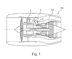
- FIG. 1 shows a sectional view of an aircraft engine comprising an embodiment of a device for the extraction of bleed air.
- FIG. 2A shows a perspective view of an embodiment of a device for the extraction of bleed air in a first position.
- FIG. 2B shows a perspective view of an embodiment of a device of FIG. 2A in a second position.
- FIG. 2C shows a perspective view of the embodiment of FIGS. 2A and 2B from below.
- FIG. 3A shows a perspective view of an embodiment of a device for the extraction of bleed air in a first position with a symbolic illustration of the flow.
- FIG. 3B shows a perspective view of an embodiment of a device for the extraction of bleed air in a second position with a symbolic illustration of the flow.
- FIG. 1 a schematic sectional view through an aircraft engine 100 that includes a per se known device 5 for the extraction of bleed air Z is shown.
- the device 5 protrudes into the flowing air L in the bypass duct 101 rigidly and permanently, so that the bleed air Z is extracted from the flowing air L.
- the inlet cross section A of the opening 1 for the flowing air is constant and cannot be modified during operation.
- the bleed air Z is guided, e.g. for cooling purposes, into the interior of the aircraft engine 100 , or it is used for air conditioning the passenger cabin.
- the bleed air Z can be diverted from another air flow, e.g. from the open air flow around the aircraft engine 100 , and used for other purposes, like the air conditioning of the cabin of an aircraft, for example.
- FIGS. 2A and 2B an embodiment of a device 5 for the extraction of bleed air Z is shown in different positions.
- the device 5 for the extraction of bleed air Z has an inlet cross section A.
- the inlet cross section A is connected to the opening 1 (see FIG. 2C ) via a bent channel.
- the inlet cross section A is positioned substantially perpendicular to the flowing air L (see FIG. 1 ).
- the device 5 for the extraction of bleed air Z has a first element 2 A, which is arranged above a second element 2 B, wherein the first element 2 A is configured so as to be moveable with respect to the second element 2 B.
- the first element 2 A is formed in a substantially groove-shaped manner in the shape of a half-shell, wherein the opening of the groove or half-shell is facing downwards.
- the second element 2 B is formed as a kind of rigid plate or a half-shell here that is opened upwards and that limits the groove of the first element 2 A towards the bottom.
- the first element 2 A can be pivoted around an axis 10 (indicated by a double arrow in FIG. 2A ), so that the distance between the elements 2 A, 2 B is changed.
- the first element 2 A is pivoted downwards (e.g. in a stepless manner) the distance decreases, so that the inlet cross section A becomes smaller (see FIG. 2B ).
- the inlet cross section A is enlarged accordingly (see FIG. 2A ).
- bleed air Z can be diverted from the flowing air L in a controlled manner. Subsequently, it is guided through an opening 1 for bleed air (see FIG. 2C ) into the internal space of the housing of the core engine, e.g. to cool certain areas of a turbine wall.
- the inlet cross section A is substantially rectangular.
- the inlet cross section A can also have other shapes, e.g. if the top side of the first element 2 A is configured in a bent manner, with the second element 2 B being adjusted accordingly.
- top first element 2 A is configured so as to be moveable with respect to a rigid bottom second element 2 B.
- this can also be different, i.e. the second element 2 B can be moveable and the first element 2 A can be configured so as to be rigid.
- the two elements 2 A, 2 B can also be configured so as to be moveable with respect to one other.
- a flow guide element 20 is arranged by which it is ensured that boundary layer flows are selectively separated and diverted into the bypass duct 101 ; this occurs independently of the size of the inlet cross section A.
- FIGS. 3A , 3 B show the same embodiment as FIGS. 2A , 2 B, so that the aforementioned description can be referred to.
- FIGS. 3A , 3 B the different portions of the flow are represented by arrows.
- the flowing air L overflows the device 5 for the extraction of bleed air Z, wherein the bleed air Z is received through the device 5 and is guided to the opening 1 (see FIG. 2C ).
- a boundary layer flow G is selectively guided around the device 5 .
- the connection area between the elements 2 A, 2 B and the wall 102 is configured as a flow guide means 20 .
- the flow guide means 20 has a substantially triangular cross section, wherein the tip (in particular a nose) of the triangle is pointing into the flow in a rounded manner.
- the flow L that is approaching the air inlet can moisten and flow around the exterior surfaces of the conduit that surrounds the inlet cross section A of the air inlet along its entire circumference. This facilitates that a boundary layer, which is present in the area of the air inlet on the wall, is separated from the air flow received into the air inlet. This is advantageous with view to a maximization of the total pressure level that can be achieved in the air intake. Further it is advantageous when, in the transition area to the wall, the air inlet is designed in such a manner that the boundary layer which is approaching the base of the intake is submitted to as little congestion as possible, which may be achieved through a narrow shape of the profile of the air inlet base around which the boundary layer streams.
- a rounded and yet substantially wedge-shaped nose of the said profile is advantageous here. It is advantageous when the nose of the profile is provided not directly or immediately in the area of the inlet cross section (A) of the air inlet. What is advantageous is a distance of the nose to the edge of the inlet cross section (A) of at least 10% of the circumference of the inlet cross section (A). Further advantages are provided by a spacing of at least 25% of the circumference of the inlet cross section (A).
Landscapes
- Engineering & Computer Science (AREA)
- Mechanical Engineering (AREA)
- General Engineering & Computer Science (AREA)
- Chemical & Material Sciences (AREA)
- Combustion & Propulsion (AREA)
- Physics & Mathematics (AREA)
- Fluid Mechanics (AREA)
- Structures Of Non-Positive Displacement Pumps (AREA)
Abstract
Description
- This application claims priority to German Patent Application DE102014217829.0 filed Sep. 5, 2014, the entirety of which is incorporated by reference herein.
- The invention relates to a device for the extraction of bleed air and to an aircraft engine.
- During operation of an aircraft engine, it may be necessary that a certain amount of air is diverted from the flowing air, so that it may serve as cooling air or as air for air conditioning of a passenger cabin, for example. In the following, the diverted air will be referred to as bleed air.
- The flowing air from which the bleed air is extracted can flow through a bypass duct or around the aircraft engine, for example.
- Known devices for the extraction of bleed air permanently protrude into the air flow and, because of their rigid intake opening, constitute a flow resistance, even if no bleed air is required from the aircraft engine.
- Therefore, there exists the objective to design the extraction of bleed air in a way that is efficient from the flow-engineering perspective.
- An adjustable air inlet for the specific adjustment of an inlet cross section of an opening located in or at a wall of the aircraft engine makes it possible to extract bleed air in a variable manner, in particular a manner that may be adjusted based on the given requirements. The extraction of bleed air can be controlled based on how the inlet cross section is oriented in relation to the flowing air.
- In order to avoid flow resistance, the adjustable air inlet is coupled to a flow guide means for the purpose guiding, in particular for a separation of a boundary layer flow. Here, the means for guiding the boundary layer flow can be arranged at the transition area of the adjustable air inlet to the wall.
- In order to divert the bleed in an efficient manner, one embodiment has an adjustable air inlet with a bent section that protrudes into the flowing air, wherein the inlet cross section is arranged at that end of the bent section that is facing towards the inward flow.
- At that, in a first position, the inlet cross section can be closed or orientated in such a manner that no bleed air or substantially no bleed air passes through an opening in the wall.
- Here, in one embodiment, a first element and a second element can be provided, which are configured so as to be moveable with respect to one another, so that the elements form the inlet cross section in the first position, and the elements seal or substantially seal the inlet cross section in the second position. A simple design is arrived at when the first element is configured so as to be moveable and so as to have a substantially groove-shaped cross section, wherein the second element is arranged in the groove-shaped cross section with a substantially rigid plate, so that the inlet cross section is formed, where necessary in a moveable manner, between the first element and the second element. The combination of a groove-shaped element and a plate-shaped part arranged therein facilitates a stable design of the adjustable air inlet.
- In another embodiment, the adjusting means comprises an electric, hydraulic and / or pneumatic actuator for adjusting the inlet cross section. These can transfer relatively strong forces in a space-saving manner.
- In one embodiment, the flow guide means has a rounded, substantially wedge-shaped nose that is directed into the boundary layer flow. Here, it can be particularly expedient if the nose of the flow guide means is not arranged in the immediate area of the inlet cross section, in particular if there is a distance of the nose to the edge of the inlet cross section of at least 10% of the circumference of the inlet cross section, in particular of at least 25% of the circumference of the inlet cross section.
- The objective is also solved by an aircraft engine with the features as described herein.
- Exemplary embodiments of the invention are shown in the following figures.
-
FIG. 1 shows a sectional view of an aircraft engine comprising an embodiment of a device for the extraction of bleed air. -
FIG. 2A shows a perspective view of an embodiment of a device for the extraction of bleed air in a first position. -
FIG. 2B shows a perspective view of an embodiment of a device ofFIG. 2A in a second position. -
FIG. 2C shows a perspective view of the embodiment ofFIGS. 2A and 2B from below. -
FIG. 3A shows a perspective view of an embodiment of a device for the extraction of bleed air in a first position with a symbolic illustration of the flow. -
FIG. 3B shows a perspective view of an embodiment of a device for the extraction of bleed air in a second position with a symbolic illustration of the flow. - In
FIG. 1 , a schematic sectional view through anaircraft engine 100 that includes a per se knowndevice 5 for the extraction of bleed air Z is shown. Here, thedevice 5 protrudes into the flowing air L in thebypass duct 101 rigidly and permanently, so that the bleed air Z is extracted from the flowing air L. Here, the inlet cross section A of the opening 1 for the flowing air is constant and cannot be modified during operation. - After having been diverted from the flowing air L, the bleed air Z is guided, e.g. for cooling purposes, into the interior of the
aircraft engine 100, or it is used for air conditioning the passenger cabin. - In alternative embodiments, the bleed air Z can be diverted from another air flow, e.g. from the open air flow around the
aircraft engine 100, and used for other purposes, like the air conditioning of the cabin of an aircraft, for example. - In the following, embodiments of the
device 5 for the extraction of bleed air Z are shown, in which a specific adjustment of an inlet cross section A of an opening 1 for bleed air Z is facilitated by means of an adjusting means 10. - In
FIGS. 2A and 2B , an embodiment of adevice 5 for the extraction of bleed air Z is shown in different positions. Here, thedevice 5 for the extraction of bleed air Z has an inlet cross section A. The inlet cross section A is connected to the opening 1 (seeFIG. 2C ) via a bent channel. - In this embodiment, the inlet cross section A is positioned substantially perpendicular to the flowing air L (see
FIG. 1 ). Here, thedevice 5 for the extraction of bleed air Z has afirst element 2A, which is arranged above asecond element 2B, wherein thefirst element 2A is configured so as to be moveable with respect to thesecond element 2B. - Here, the
first element 2A is formed in a substantially groove-shaped manner in the shape of a half-shell, wherein the opening of the groove or half-shell is facing downwards. Thesecond element 2B is formed as a kind of rigid plate or a half-shell here that is opened upwards and that limits the groove of thefirst element 2A towards the bottom. - The
first element 2A can be pivoted around an axis 10 (indicated by a double arrow inFIG. 2A ), so that the distance between theelements first element 2A is pivoted downwards (e.g. in a stepless manner) the distance decreases, so that the inlet cross section A becomes smaller (seeFIG. 2B ). Through upward pivoting, the inlet cross section A is enlarged accordingly (seeFIG. 2A ). - In this manner, bleed air Z can be diverted from the flowing air L in a controlled manner. Subsequently, it is guided through an opening 1 for bleed air (see
FIG. 2C ) into the internal space of the housing of the core engine, e.g. to cool certain areas of a turbine wall. - Hereby, a substantially complete sealing can be achieved if the
elements - In the shown embodiment, the inlet cross section A is substantially rectangular. In alternative embodiments, the inlet cross section A can also have other shapes, e.g. if the top side of the
first element 2A is configured in a bent manner, with thesecond element 2B being adjusted accordingly. - It is also not obligatory that the top
first element 2A is configured so as to be moveable with respect to a rigid bottomsecond element 2B. In alternative embodiments this can also be different, i.e. thesecond element 2B can be moveable and thefirst element 2A can be configured so as to be rigid. The twoelements - Below the inlet cross section A, a
flow guide element 20 is arranged by which it is ensured that boundary layer flows are selectively separated and diverted into thebypass duct 101; this occurs independently of the size of the inlet cross section A. -
FIGS. 3A , 3B show the same embodiment asFIGS. 2A , 2B, so that the aforementioned description can be referred to. - In addition, in
FIGS. 3A , 3B the different portions of the flow are represented by arrows. - The flowing air L overflows the
device 5 for the extraction of bleed air Z, wherein the bleed air Z is received through thedevice 5 and is guided to the opening 1 (seeFIG. 2C ). A boundary layer flow G is selectively guided around thedevice 5. For this purpose, the connection area between theelements wall 102 is configured as a flow guide means 20. In a top view, the flow guide means 20 has a substantially triangular cross section, wherein the tip (in particular a nose) of the triangle is pointing into the flow in a rounded manner. - It is advantageous here if the flow L that is approaching the air inlet can moisten and flow around the exterior surfaces of the conduit that surrounds the inlet cross section A of the air inlet along its entire circumference. This facilitates that a boundary layer, which is present in the area of the air inlet on the wall, is separated from the air flow received into the air inlet. This is advantageous with view to a maximization of the total pressure level that can be achieved in the air intake. Further it is advantageous when, in the transition area to the wall, the air inlet is designed in such a manner that the boundary layer which is approaching the base of the intake is submitted to as little congestion as possible, which may be achieved through a narrow shape of the profile of the air inlet base around which the boundary layer streams. A rounded and yet substantially wedge-shaped nose of the said profile is advantageous here. It is advantageous when the nose of the profile is provided not directly or immediately in the area of the inlet cross section (A) of the air inlet. What is advantageous is a distance of the nose to the edge of the inlet cross section (A) of at least 10% of the circumference of the inlet cross section (A). Further advantages are provided by a spacing of at least 25% of the circumference of the inlet cross section (A).
-
- 1 opening for bleed air
- 2A top (moveable) element
- 2B bottom (stationary) element
- 5 device for the extraction of bleed air
- 10 axis
- 20 flow guide element
- 100 aircraft engine
- 101 bypass duct
- 102 wall (fairing)
- A inlet cross section
- G boundary layer flow
- L flowing air
- Z bleed air
Claims (11)
Applications Claiming Priority (3)
| Application Number | Priority Date | Filing Date | Title |
|---|---|---|---|
| DE102014217829.0 | 2014-09-05 | ||
| DE102014217829 | 2014-09-05 | ||
| DE102014217829.0A DE102014217829A1 (en) | 2014-09-05 | 2014-09-05 | Method for drawing bleed air and aircraft engine with at least one device for drawing bleed air |
Publications (2)
| Publication Number | Publication Date |
|---|---|
| US20160069273A1 true US20160069273A1 (en) | 2016-03-10 |
| US10113485B2 US10113485B2 (en) | 2018-10-30 |
Family
ID=54065216
Family Applications (1)
| Application Number | Title | Priority Date | Filing Date |
|---|---|---|---|
| US14/845,872 Expired - Fee Related US10113485B2 (en) | 2014-09-05 | 2015-09-04 | Device for the extraction of bleed air and aircraft engine with at least one device for the extraction of bleed air |
Country Status (3)
| Country | Link |
|---|---|
| US (1) | US10113485B2 (en) |
| EP (1) | EP2993337B1 (en) |
| DE (1) | DE102014217829A1 (en) |
Cited By (4)
| Publication number | Priority date | Publication date | Assignee | Title |
|---|---|---|---|---|
| EP3258066B1 (en) * | 2016-06-16 | 2021-07-21 | Doosan Heavy Industries & Construction Co., Ltd. | Air flow guide cap for a combustion duct of a gas turbine engine |
| CN114542287A (en) * | 2022-02-17 | 2022-05-27 | 中国航发沈阳发动机研究所 | An air bleed structure for reducing the circumferential temperature non-uniformity of the casing wall |
| US11434822B2 (en) | 2015-06-19 | 2022-09-06 | Raytheon Technologies Corporation | Inverse modulation of secondary bleed |
| CN116788540A (en) * | 2023-06-27 | 2023-09-22 | 中国电子科技集团公司第五十四研究所 | Low-compensation unmanned aerial vehicle cooling environmental control system and cooling method thereof |
Families Citing this family (2)
| Publication number | Priority date | Publication date | Assignee | Title |
|---|---|---|---|---|
| FR3057244B1 (en) * | 2016-10-12 | 2020-06-12 | Safran Aircraft Engines | IMPROVED TURBOMACHINE VENTILATION DEVICE |
| US12188408B1 (en) * | 2023-07-31 | 2025-01-07 | Rolls-Royce North American Technologies Inc. | Inlet turning vanes having trailing edge features for improved flow uniformity |
Citations (1)
| Publication number | Priority date | Publication date | Assignee | Title |
|---|---|---|---|---|
| US8439061B2 (en) * | 2005-11-10 | 2013-05-14 | Airbus Deutschland Gmbh | Emergency ram air inlet valve of an aircraft |
Family Cites Families (11)
| Publication number | Priority date | Publication date | Assignee | Title |
|---|---|---|---|---|
| DE854894C (en) * | 1944-08-17 | 1952-11-06 | Daimler Benz Ag | Air intake hood for aircraft |
| US4121606A (en) * | 1977-10-25 | 1978-10-24 | General Dynamics Corporation | Inflatable air inlet duct |
| US4250703A (en) | 1979-03-15 | 1981-02-17 | Avco Corporation | Swinging door particle separator and deicing system |
| DE3521329A1 (en) * | 1985-06-14 | 1986-12-18 | Messerschmitt-Bölkow-Blohm GmbH, 8012 Ottobrunn | Vortex generator and boundary layer deflector arrangement |
| GB2259328B (en) * | 1991-09-03 | 1995-07-19 | Gen Electric | Gas turbine engine variable bleed pivotal flow splitter |
| US6349899B1 (en) * | 2000-04-04 | 2002-02-26 | The Boeing Company | Aircraft auxiliary air intake with ram and flush opening door |
| US20060288688A1 (en) * | 2005-06-22 | 2006-12-28 | Jean-Pierre Lair | Turbofan core thrust spoiler |
| US7861968B2 (en) * | 2006-10-26 | 2011-01-04 | The Boeing Company | Air inlet and method for a highspeed mobile platform |
| US20100132367A1 (en) | 2007-05-25 | 2010-06-03 | Volvo Aero Corporation | Device for moving a plurality of hatches in a gas turbine engine |
| US9045998B2 (en) * | 2011-12-12 | 2015-06-02 | Honeywell International Inc. | System for directing air flow to a plurality of plena |
| US9108737B2 (en) * | 2012-08-24 | 2015-08-18 | United Technologies Corporation | Nacelle scoop inlet |
-
2014
- 2014-09-05 DE DE102014217829.0A patent/DE102014217829A1/en not_active Withdrawn
-
2015
- 2015-09-03 EP EP15183752.3A patent/EP2993337B1/en active Active
- 2015-09-04 US US14/845,872 patent/US10113485B2/en not_active Expired - Fee Related
Patent Citations (1)
| Publication number | Priority date | Publication date | Assignee | Title |
|---|---|---|---|---|
| US8439061B2 (en) * | 2005-11-10 | 2013-05-14 | Airbus Deutschland Gmbh | Emergency ram air inlet valve of an aircraft |
Cited By (5)
| Publication number | Priority date | Publication date | Assignee | Title |
|---|---|---|---|---|
| US11434822B2 (en) | 2015-06-19 | 2022-09-06 | Raytheon Technologies Corporation | Inverse modulation of secondary bleed |
| US11746702B2 (en) | 2015-06-19 | 2023-09-05 | Raytheon Technologies Corporation | Inverse modulation of secondary bleed |
| EP3258066B1 (en) * | 2016-06-16 | 2021-07-21 | Doosan Heavy Industries & Construction Co., Ltd. | Air flow guide cap for a combustion duct of a gas turbine engine |
| CN114542287A (en) * | 2022-02-17 | 2022-05-27 | 中国航发沈阳发动机研究所 | An air bleed structure for reducing the circumferential temperature non-uniformity of the casing wall |
| CN116788540A (en) * | 2023-06-27 | 2023-09-22 | 中国电子科技集团公司第五十四研究所 | Low-compensation unmanned aerial vehicle cooling environmental control system and cooling method thereof |
Also Published As
| Publication number | Publication date |
|---|---|
| DE102014217829A1 (en) | 2016-03-10 |
| US10113485B2 (en) | 2018-10-30 |
| EP2993337B1 (en) | 2019-11-06 |
| EP2993337A1 (en) | 2016-03-09 |
Similar Documents
| Publication | Publication Date | Title |
|---|---|---|
| US10113485B2 (en) | Device for the extraction of bleed air and aircraft engine with at least one device for the extraction of bleed air | |
| CN105682958B (en) | Air nozzle | |
| CN106660443B (en) | Motor vehicle front face with central air inlet and lateral outlets | |
| US20180265208A1 (en) | Air intake structure and airflow control system | |
| US9862482B2 (en) | Variable geometry flush boundary diverter | |
| EP2894323A1 (en) | Dual function air diverter and variable area fan nozzle | |
| US20180354346A1 (en) | Air vent for a vehicle | |
| US20090111370A1 (en) | Ventilating air intake arrangement with mobile closing device | |
| US8313062B2 (en) | Extendable deflector for discharging structure-damaging fluids | |
| US9611050B2 (en) | Auxiliary power unit inlet apparatus and methods | |
| RU2010147877A (en) | DEVICE AND METHOD FOR COOLING WASTE AIR OF AIRCRAFT AIR CONDITIONING SYSTEMS | |
| US10974817B2 (en) | Vertical tail unit for flow control | |
| EP2886453B1 (en) | Boundary layer control system and aircraft having such a boundary layer control system | |
| US20130168045A1 (en) | Ram air channel arrangement and aircraft air conditioning system | |
| US10384793B2 (en) | Nacelle comprising an exchanger for cooling a stream of fluid | |
| US10001062B2 (en) | Aircraft turbine engine comprising an air intake housing with a variable aerodynamic profile | |
| EP2272758B1 (en) | Ram door assemblies | |
| EP3144224A1 (en) | Ram air channel arrangement and method for operating a ram air channel arrangement | |
| RU2015104298A (en) | MOVABLE VENTILATION HOLE OF VEHICLE | |
| EP3135964B1 (en) | Flow diverting flapper | |
| WO2018122575A1 (en) | Recirculating vertical wind tunnel with passive cooling | |
| US8826659B2 (en) | Ejector with check valve | |
| US10174674B2 (en) | Device for the extraction of bleed air and aircraft engine with at least one device for the extraction of bleed air | |
| CN108688820A (en) | Fan bypass and closing check-valves | |
| US20170341763A1 (en) | None |
Legal Events
| Date | Code | Title | Description |
|---|---|---|---|
| AS | Assignment |
Owner name: ROLLS-ROYCE DEUTSCHLAND LTD & CO KG, GERMANY Free format text: ASSIGNMENT OF ASSIGNORS INTEREST;ASSIGNORS:BURGHARDT, SASCHA;GUEMMER, VOLKER;REEL/FRAME:046735/0840 Effective date: 20150915 |
|
| STCF | Information on status: patent grant |
Free format text: PATENTED CASE |
|
| FEPP | Fee payment procedure |
Free format text: MAINTENANCE FEE REMINDER MAILED (ORIGINAL EVENT CODE: REM.); ENTITY STATUS OF PATENT OWNER: LARGE ENTITY |
|
| LAPS | Lapse for failure to pay maintenance fees |
Free format text: PATENT EXPIRED FOR FAILURE TO PAY MAINTENANCE FEES (ORIGINAL EVENT CODE: EXP.); ENTITY STATUS OF PATENT OWNER: LARGE ENTITY |
|
| STCH | Information on status: patent discontinuation |
Free format text: PATENT EXPIRED DUE TO NONPAYMENT OF MAINTENANCE FEES UNDER 37 CFR 1.362 |
|
| FP | Lapsed due to failure to pay maintenance fee |
Effective date: 20221030 |