US20150262375A1 - Speed calculating device and speed calculating method, and collision determination device - Google Patents
Speed calculating device and speed calculating method, and collision determination device Download PDFInfo
- Publication number
- US20150262375A1 US20150262375A1 US14/425,063 US201214425063A US2015262375A1 US 20150262375 A1 US20150262375 A1 US 20150262375A1 US 201214425063 A US201214425063 A US 201214425063A US 2015262375 A1 US2015262375 A1 US 2015262375A1
- Authority
- US
- United States
- Prior art keywords
- speed
- image
- moving body
- distance
- calculates
- Prior art date
- Legal status (The legal status is an assumption and is not a legal conclusion. Google has not performed a legal analysis and makes no representation as to the accuracy of the status listed.)
- Granted
Links
Images

Classifications
-
- G—PHYSICS
- G06—COMPUTING; CALCULATING OR COUNTING
- G06V—IMAGE OR VIDEO RECOGNITION OR UNDERSTANDING
- G06V20/00—Scenes; Scene-specific elements
- G06V20/50—Context or environment of the image
- G06V20/56—Context or environment of the image exterior to a vehicle by using sensors mounted on the vehicle
- G06V20/58—Recognition of moving objects or obstacles, e.g. vehicles or pedestrians; Recognition of traffic objects, e.g. traffic signs, traffic lights or roads
-
- G—PHYSICS
- G06—COMPUTING; CALCULATING OR COUNTING
- G06T—IMAGE DATA PROCESSING OR GENERATION, IN GENERAL
- G06T7/00—Image analysis
- G06T7/20—Analysis of motion
-
- G—PHYSICS
- G08—SIGNALLING
- G08G—TRAFFIC CONTROL SYSTEMS
- G08G1/00—Traffic control systems for road vehicles
- G08G1/16—Anti-collision systems
- G08G1/166—Anti-collision systems for active traffic, e.g. moving vehicles, pedestrians, bikes
-
- G—PHYSICS
- G01—MEASURING; TESTING
- G01S—RADIO DIRECTION-FINDING; RADIO NAVIGATION; DETERMINING DISTANCE OR VELOCITY BY USE OF RADIO WAVES; LOCATING OR PRESENCE-DETECTING BY USE OF THE REFLECTION OR RERADIATION OF RADIO WAVES; ANALOGOUS ARRANGEMENTS USING OTHER WAVES
- G01S13/00—Systems using the reflection or reradiation of radio waves, e.g. radar systems; Analogous systems using reflection or reradiation of waves whose nature or wavelength is irrelevant or unspecified
- G01S13/02—Systems using reflection of radio waves, e.g. primary radar systems; Analogous systems
- G01S13/04—Systems determining presence of a target
-
- G—PHYSICS
- G01—MEASURING; TESTING
- G01S—RADIO DIRECTION-FINDING; RADIO NAVIGATION; DETERMINING DISTANCE OR VELOCITY BY USE OF RADIO WAVES; LOCATING OR PRESENCE-DETECTING BY USE OF THE REFLECTION OR RERADIATION OF RADIO WAVES; ANALOGOUS ARRANGEMENTS USING OTHER WAVES
- G01S13/00—Systems using the reflection or reradiation of radio waves, e.g. radar systems; Analogous systems using reflection or reradiation of waves whose nature or wavelength is irrelevant or unspecified
- G01S13/86—Combinations of radar systems with non-radar systems, e.g. sonar, direction finder
- G01S13/867—Combination of radar systems with cameras
-
- G—PHYSICS
- G01—MEASURING; TESTING
- G01S—RADIO DIRECTION-FINDING; RADIO NAVIGATION; DETERMINING DISTANCE OR VELOCITY BY USE OF RADIO WAVES; LOCATING OR PRESENCE-DETECTING BY USE OF THE REFLECTION OR RERADIATION OF RADIO WAVES; ANALOGOUS ARRANGEMENTS USING OTHER WAVES
- G01S17/00—Systems using the reflection or reradiation of electromagnetic waves other than radio waves, e.g. lidar systems
- G01S17/88—Lidar systems specially adapted for specific applications
- G01S17/93—Lidar systems specially adapted for specific applications for anti-collision purposes
- G01S17/931—Lidar systems specially adapted for specific applications for anti-collision purposes of land vehicles
Definitions
- the present invention relates to a speed calculating device, a speed calculating method, and a collision determination device which calculate the speed of an object around a moving body.
- Japanese Unexamined Patent Application Publication No. 2010-146494 discloses a device which switches a detection algorithm for short distance and a detection algorithm for long distance to detect an object in front of a vehicle, on the basis of whether the distance to the object is less than a threshold value.
- Patent Literature 1 Japanese Unexamined Patent Application Publication No. 2010-146494
- the device calculates the speed of the object, using different algorithms in a situation in which the distance to the object is slightly less than the threshold value and a situation in which the distance to the object is slightly greater than the threshold value. Therefore, when there is a large difference in the calculation result of the speed of the object, the moving body is not smoothly controlled and the operator of the moving body feels discomfort.
- An object of the invention is to provide a speed calculating device, a speed calculating method, and a collision determination device which can accurately calculate the speed of an object around a moving body such that the operator of a moving body does not feel discomfort.
- a speed calculating device that calculates a speed of an object around a moving body.
- the speed calculating device includes: an image detection unit that captures an image of the surroundings of the moving body and detects the object from the captured image; and a speed calculation unit that calculates the speed of the object, using a moving body speed indicating the speed of the moving body and an image speed, which indicates the speed of the object and is calculated from the image, at a ratio corresponding to a distance from the moving body to the object.
- the speed calculation unit calculates the speed of the object using the moving body speed and the image speed such that the ratio of the moving body speed increases as the distance to the object increases and the ratio of the image speed increases as the distance to the object decreases.
- the speed of the object is calculated using the moving body speed and the image speed at a ratio corresponding to the distance to the object. Therefore, it is possible to accurately calculate the speed of a distant object and the speed of a near object according to a change in the distance to the object. As the distance to the object increases, the accuracy of the image speed is reduced. Therefore, in particular, the ratio of the moving body speed increases in order to calculate the speed of the distant object and the ratio of the image speed increases in order to calculate the speed of the near object. As a result, it is possible to accurately calculate the speed of the object.
- the speed calculating device may further include a radar detection unit that detects the object using a radar wave.
- the speed calculation unit may calculate the speed of the object, using the moving body speed and the image speed. According to this structure, the detection result obtained by the radar wave and the detection result obtained by the image can be appropriately used according to the detection situation of the object to calculate the speed of the object.
- the speed calculating device may further include a composite target generation unit that generates a composite target of the object using a detection result obtained by the radar detection unit and a detection result obtained by the image detection unit.
- the speed calculation unit may calculate the speed of the object, using the moving body speed and the image speed. According to this structure, the composite target and the detection result obtained by the image can be appropriately used according to the detection situation of the radar detection unit to calculate the speed of the object.
- the speed calculating device may further include a radar detection unit that detects the object using a radar wave.
- the speed calculation unit may calculate the speed of the object, using the moving body speed and the image speed. According to this structure, the detection result obtained by the radar wave and the detection result obtained by the image can be appropriately used according to the position of the object to calculate the speed of the object.
- the speed calculating device may further include a stationary state determination unit that determines whether the object is stationary in a traveling direction of the moving body. When it is determined that the object is stationary, the speed calculation unit may calculate the speed of the object using the moving body speed and the image speed. According to this structure, it is possible to accurately calculate the speed of the object using the moving body speed.
- the speed calculation unit may calculate the speed of the object using the moving body speed and the image speed such that the ratio of the moving body speed is 1 and the ratio of the image speed is 0. According to this structure, it is possible to accurately calculate the speed of a distant object using only the moving body speed.
- the speed calculation unit may calculate the speed of the object using the moving body speed and the image speed such that the ratio of the moving body speed is 0 and the ratio of the image speed is 1. According to this structure, it is possible to accurately calculate the speed of a near object using only the image speed.
- a collision determination device including: the above-mentioned speed calculating device; and a collision determination unit that determines a collision with the object on the basis of the speed of the object calculated by the speed calculating device. According to this structure, it is possible to determine a collision with the object on the basis of the speeds of a near object and a distant object which are accurately calculated according to a change in the distance to the object.
- the speed calculating device may capture the image of the front side of the moving body, detect the object from the captured image, and calculate the speed of the object in front of the moving body.
- the speed calculating device may capture an image in the traveling direction of the moving body, detect the object from the captured image, and calculate the speed of the object in the traveling direction of the moving body.
- the moving body may be a vehicle or other moving bodies, such as a ship, an airplane, and a flying object.
- a speed calculating method that calculates a speed of an object around a moving body.
- the speed calculating method includes: capturing an image of the surroundings of the moving body and detecting the object from the captured image; and calculating the speed of the object, using a moving body speed indicating the speed of the moving body and an image speed, which indicates the speed of the object and is calculated from the image, such that the ratio of the moving body speed increases as the distance to the object increases and the ratio of the image speed increases as the distance to the object decreases.
- a speed calculating device a speed calculating method, and a collision determination device which can accurately calculate the speed of an object around a vehicle such that the operator of a moving body does not feel discomfort.
- FIG. 1 is a block diagram illustrating the structure of a collision determination device according to a first embodiment of the invention.
- FIG. 2 is a flowchart illustrating the operation of the collision determination device.
- FIG. 3 is a diagram illustrating an example of a distance coefficient map.
- FIG. 4 is a diagram illustrating the comparison between the calculation result of a collision time based on an image speed and the calculation result of a collision time based on a vehicle speed and the image speed.
- FIG. 5 is a block diagram illustrating the structure of a collision determination device according to a second embodiment of the invention.
- FIG. 6 is a diagram illustrating the detection ranges of a stereo camera and a radar.
- FIG. 7 is a flowchart illustrating the operation of the collision determination device.
- a speed calculating device, a speed calculating method, and a collision determination device will be described below.
- the speed calculating device and the speed calculating method calculate the speed of an object around a moving body.
- the collision determination device determines a collision with the object on the basis of the speed of the object calculated by the speed calculating device.
- the moving body is a vehicle and the collision determination device determines a collision with an object on the basis of the speed of the object calculated by the speed calculating device that calculates the speed of the object around the vehicle, particularly, in front of the vehicle.
- the moving body is not limited to the vehicle and may be, for example, a ship, an airplane, or a flying object.
- the position where the speed of the object is calculated by the speed calculating device is not limited to the front side of the moving body and the speed calculating device may calculate the speed of the object in the traveling direction of the moving body.
- the collision determination device may determine a collision with the object on the basis of the speed of the object.
- the collision determination device according to a first embodiment of the invention will be described with reference to FIGS. 1 to 4 .
- the collision determination device is provided in the vehicle and determines a collision between the vehicle and the object using an image sensor.
- the collision determination device also functions as a speed calculating device which calculates the speed of the object using the image sensor.
- the object includes a moving body and a stationary body and is an obstacle which prevents the traveling of the vehicle, such as, a vehicle in front, an oncoming vehicle, a bicycle, a pedestrian, a parked vehicle, or a guardrail.
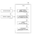
- FIG. 1 is a block diagram illustrating the structure of the collision determination device according to the first embodiment.
- the collision determination device includes a speed sensor 11 , a stereo camera 12 , and an electronic control unit (ECU) 20 .
- ECU electronice control unit
- the speed sensor 11 detects the speed of the vehicle.
- a wheel speed sensor is used as the speed sensor 11 .
- the speed sensor 11 supplies the detected vehicle speed (absolute speed) to the ECU 20 .
- the stereo camera 12 functions as an image detection unit (image sensor) which captures the image of the front side of the vehicle and detects the object on the basis of the captured image.
- image sensor image sensor
- a charge-coupled device (CCD) or a complementary metal-oxide semiconductor (CMOS) sensor is used as the stereo camera 12 .
- the stereo camera 12 includes a plurality of cameras and is provided on the front surface of the vehicle or in the cabin of the vehicle.
- the stereo camera 12 supplies image detection information indicating the detection result of the object to the ECU 20 .
- a single camera may be used instead of the stereo camera 12 .
- the ECU 20 includes an image target generation unit 21 , a stationary state determination unit 24 , a speed calculation unit 25 , and a collision determination unit 26 .
- the ECU 20 includes, for example, a CPU, a ROM, and a RAM as main components.
- the CPU executes a program to implement the functions of the image target generation unit 21 , the stationary state determination unit 24 , the speed calculation unit 25 , and the collision determination unit 26 .
- the ECU 20 may be a single unit or it may include a plurality of units.
- the image target generation unit 21 generates an image target on the basis of the image detection information from the stereo camera 12 .
- the image target has target information related to the distance to the object and the lateral position of the object which are calculated from the coordinates of the vehicle as a reference point.
- the target information of the image target is calculated by the principle of triangulation, on the basis of the deviation between the image detection information items of the left and right cameras forming the stereo camera 12 , or it is calculated on the basis of the detection size and position of, for example, a number plate of the vehicle in front.
- the distance to the object indicates the distance from the vehicle (stereo camera 12 ) to the object in the traveling direction of the vehicle.
- the lateral position of the object indicates the distance from the vehicle (stereo camera 12 ) to the object in a direction perpendicular to the traveling direction of the vehicle.
- the lateral position of the image target also includes the range of the object detected from the image in the lateral direction, that is, information about the width of the object.
- the image target generation unit 21 calculates an image speed (absolute speed) from the image detection information indicating the speed of the object.
- the image speed is calculated on the basis of the distance to the object and the vehicle speed, using the target information of the image target.
- the image speed is calculated on the basis of, for example, a change in the distance to the object in consecutive cycles. For example, the image speed is calculated by dividing the difference between the distance in a processing cycle i and the distance in a processing cycle i+1 by the interval of the processing cycle and reducing the vehicle speed from the divided value.
- a process of averaging the calculated values in the consecutive processing cycles may be performed in order to reduce a calculation error.
- the stationary state determination unit 24 determines whether the object in front of the vehicle is stationary on the basis of the image speed.
- the stationary state of the object means that the speed (absolute speed) of the object in the traveling direction of the vehicle is 0 or substantially 0. For example, a pedestrian who crosses in front of the vehicle is assumed as the object.
- the speed calculation unit 25 calculates the speed (relative speed) of the object on the basis of the vehicle speed and the target information of the image target.
- the speed calculation unit 25 calculates the speed of the object, using the vehicle speed indicating the speed of the vehicle and the image speed indicating the speed of the object at a ratio corresponding to the distance to the object.
- the speed calculation unit 25 sets the ratio corresponding to the distance to the object such that the ratio of the vehicle speed increases as the distance to the object increases and the ratio of the image speed increases as the distance to the object decreases.
- the speed calculation unit 25 may calculate the speed of the object using the vehicle speed and the image speed only when the object in front of the vehicle is stationary.
- the collision determination unit 26 determines a collision with the object on the basis of the speed of the object calculated by the speed calculation unit 25 .
- the collision determination unit 26 determines the possibility of a collision with the object on the basis of whether a collision time obtained by dividing the distance to the object by the speed of the object is less than a predetermined threshold value. For example, the determination result of the collision possibility is used to notify the driver of information or to control the braking or steering of the vehicle to support collision avoidance.
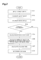
- FIG. 2 is a flowchart illustrating the operation of the collision determination device.
- the collision determination device repeatedly performs the process shown in FIG. 2 in a predetermined cycle.
- the speed sensor 11 detects the vehicle speed (absolute speed) (Step S 11 ).
- the image target generation unit 21 When there is an object in the detection range of the stereo camera 12 , the image target generation unit 21 generates an image target (S 12 ).
- the image target generation unit 21 calculates the image speed (absolute speed) from the image detection information indicating the speed of the object (S 13 ).
- the stationary state determination unit 24 determines whether the object in front of the vehicle is stationary on the basis of the image speed (S 14 ). This is because the accuracy of calculating the speed of the object on the basis of the vehicle speed can increase as the speed of the object in the traveling direction of the vehicle is reduced. However, the process in S 14 may be omitted.
- the process in S 15 and the subsequent steps is performed if it is determined in S 14 that the object is stationary. If it is determined in S 14 that the object is not stationary, the process is not performed and ends. In addition, it may be determined whether the object is a pedestrian who crosses a road on the basis of image recognition or it may be determined whether the object is present at the position of a crosswalk on the basis of image recognition or map information, instead of determining whether the object is stationary.
- the speed calculation unit 25 calculates a distance coefficient corresponding to the distance to the object, using the target information of the image target (S 15 ).
- the distance coefficient is a coefficient indicating the ratio (weighting) of the vehicle speed and the image speed used to calculate the speed of the object and is calculated using, for example, a distance coefficient map which will be described below.
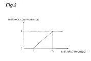
- FIG. 3 is a diagram illustrating an example of the distance coefficient map.
- the distance coefficient map indicates the relationship between the distance to the object on the horizontal axis and the distance coefficient on the vertical axis.
- the lower limit T 1 and upper limit Tu of the distance are set on the distance coefficient map.
- the distance coefficient indicates the ratio (0 to 1) of the vehicle speed when the sum of the ratio of the vehicle speed and the ratio of the image speed is 1.
- the distance coefficient is set to “0” when the distance to the object is equal to or less than the lower limit T 1 , is set to “1” when the distance is equal to or greater than the upper limit Tu, and is set to a value between “0” and “1” when the distance is between the lower limit T 1 and the upper limit Tu.
- the distance coefficient is set so as to monotonically increase between the lower limit T 1 and the upper limit Tu.
- the distance coefficient may be set so as to increase in different manners.
- the speed calculation unit 25 calculates the speed (relative speed) V of the object on the basis of the distance coefficient (p), the vehicle speed (V 1 ), and the image speed (V 2 ) (S 16 ).
- the speed V of the object is calculated by the following expression:
- the speed of the object is calculated using only the image speed when the distance to the object is equal to or less than the lower limit T 1 and is calculated using only the vehicle speed when the distance is equal to or greater than the upper limit Tu.
- the speed of the object is calculated using (with a larger weight) a higher ratio of the vehicle speed as the distance to the object increases and is calculated using (with a larger weight) a higher ratio of the image speed as the distance to the object decreases.
- the collision determination unit 26 divides the distance to the object by the speed of the object to calculate a collision time (S 17 ). Then, the collision determination unit 26 determines a collision with the object on the basis of whether the collision time is less than a predetermined threshold value (S 18 ).
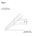
- FIG. 4 is a diagram illustrating the comparison between the calculation result of the collision time based on the image speed and the calculation result of the collision time based on the vehicle speed and the image speed.
- the collision time based on the image speed is calculated by dividing the distance to the object by the speed of the object corresponding to the image speed and the collision time based on the vehicle speed and the image speed is calculated by dividing the distance to the object by the speed of the object calculated on the basis of the vehicle speed and the image speed.
- the horizontal axis indicates the actually measured collision time and the vertical axis indicates the calculation result of the collision time.
- FIG. 4 shows a variation in the calculation result of the collision time due to a variation in the distance to the object.
- a dashed line indicates the range V 1 of the variation in the calculation result based on the image speed and a solid line indicates the range V 2 of the variation in the calculation result based on the vehicle speed and the image speed.
- V 2 the variation in the calculation result based on the vehicle speed and the image speed is reduced to about half the variation in the calculation result (V 1 ) based on the image speed. Therefore, when the collision time is accurately calculated, it is possible to accurately determine the collision with the object.
- the speed of the object is calculated using the vehicle speed (moving body speed) and the image speed at a ratio corresponding to the distance to the object. Therefore, it is possible to accurately calculate the speeds of a near object and a distant object according to a change in the distance to the object. As the distance to the object increases, the accuracy of the image speed is reduced. Therefore, in particular, the ratio of the vehicle speed (moving body speed) increases in order to calculate the speed of the distant object and the ratio of the image speed increases in order to calculate the speed of the near object. As a result, it is possible to accurately calculate the speed of the object.
- the speed of the object is calculated using the vehicle speed (moving body speed) and the image speed. Therefore, the speed of the object may be accurately calculated using the vehicle speed (moving body speed).
- the collision determination device of the embodiment of the invention it is possible to determine a collision with the object on the basis of the speeds of a near object and a distant object which are accurately calculated according to a change in the distance to the object.
- the speed of the object is calculated using the vehicle speed (moving body speed) and the image speed at a ratio corresponding to the distance to the object. Therefore, it is possible to accurately calculate the speeds of a near object and a distant object according to a change in the distance to the object.
- FIGS. 5 to 7 a collision determination device according to a second embodiment of the invention will be described with reference to FIGS. 5 to 7 .
- the description of the same components as those in the first embodiment will not be repeated.
- the collision determination device is provided in a vehicle and determines a collision between the vehicle and an object using a radar sensor and an image sensor.
- the collision determination device also functions as a speed calculating device which calculates the speed of the object using the radar sensor and the image sensor.
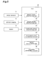
- FIG. 5 is a block diagram illustrating the structure of the collision determination device according to the second embodiment.
- the collision determination device includes a speed sensor 11 , a stereo camera 12 , an ECU 30 , and a radar 13 .
- the structure and function of the speed sensor 11 and the stereo camera 12 are the same as those in the first embodiment and thus the description thereof will not be repeated.
- the radar 13 functions as a radar detection unit (radar sensor) which detects an object in front of the vehicle using radar waves, transmits radar waves (electromagnetic waves) to the front side of the vehicle, and receives radar waves reflected from the object.
- radar detection unit radar sensor
- a microwave radar, a millimeter-wave radar, an ultrasonic radar, or a laser radar is used as the radar 13 .
- the radar 13 supplies radar detection information indicating the detection result of the object to the ECU 30 .
- the ECU 30 includes an image target generation unit 21 , a stationary state determination unit 24 , a speed calculation unit 25 , a collision determination unit 26 , a radar target generation unit 22 , and a composite target generation unit 23 .
- the ECU 30 includes, for example, a CPU, a ROM, and a RAM as main components.
- the CPU executes a program to implement the functions of the image target generation unit 21 , the radar target generation unit 22 , the composite target generation unit 23 , the stationary state determination unit 24 , the speed calculation unit 35 , and the collision determination unit 36 .
- the structure and function of the image target generation unit 21 and the stationary state determination unit 24 are the same as those in the first embodiment and thus the description thereof will not be repeated.
- the radar target generation unit 22 generates a radar target on the basis of the radar detection information from the radar 13 .
- the radar target has target information related to the distance to the object and the lateral position of the object which are calculated from the coordinates of the vehicle as a reference.
- the target information of the radar target is calculated on the basis of the radar detection information from the radar 13 .
- the distance to the object indicates the distance from the vehicle (radar 13 ) to the object in the traveling direction of the vehicle and is calculated on the basis of the time from the transmission of the radar wave from the radar 13 to the reception of the radar wave reflected from the object.
- the lateral position of the object indicates the distance from the vehicle (radar 13 ) to the object in a direction perpendicular to the traveling direction of the vehicle and is calculated on the basis of the direction (angle) of the radar wave which is reflected from the objected and is then received.
- the lateral position of the radar target is information about the position of the object detected by the radar 13 and does not include information about the width of the object.
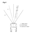
- FIG. 6 is a diagram illustrating the detection ranges A 1 and A 2 of the radar 13 and the stereo camera 12 .
- the detection range A 1 of the radar 13 is narrower than the detection range A 2 of the stereo camera 12 . Therefore, a region which can be detected only by the stereo camera 12 and is arranged outside the detection range A 1 of the radar 13 is present diagonally in front of the vehicle.
- FIG. 6 shows a target which moves from the detection ranges A 1 and A 2 of the radar 13 and the stereo camera 12 to the detection range A 2 of the stereo camera 12 .
- the radar 13 has low accuracy in the detection of the lateral position considering the width of the object and is not capable of detecting the width of the object. However, the radar 13 has high accuracy in the detection of the distance to the object. In contrast, the stereo camera 12 has low accuracy in the detection of the distance to the object but has high accuracy in the detection of the lateral position and width of the object. Therefore, the detection accuracy of an image speed which is calculated on the basis of the distance to the object in the target information of an image target is reduced as the distance to the object increases.
- the composite target generation unit 23 generates a composite target of the object, using the target information of the radar target and the image target, that is, the detection results of the radar 13 and the stereo camera 12 .
- the composite target is generated by collating the two targets on the basis of the target information of the radar target and the image target.
- the two targets are collated with each other on the basis of the similarity between the target information items of the two targets, that is, the similarity between the distances to the object and the lateral positions.
- the composite target has target information related to the distance to the object and the lateral position (including the width) of the object.
- the target information of the composite target is based on the target information of the radar target and the image target and has higher accuracy than the target information of only the radar target or the target information of only the image target.
- the speed calculation unit 35 calculates the speed (relative speed) of the object on the basis of a vehicle speed and the target information of the composite target, the radar target, or the image target.
- the speed calculation unit 35 calculates the speed of the object on the basis of the target information of the composite target. In this case, the speed of the object is calculated by dividing the distance to the object in the target information of the composite target by the interval of the processing cycle.
- the speed calculation unit 35 may calculate the speed of the object on the basis of the target information of the radar target. In this case, the speed of the object is calculated by dividing the distance to the object in the target information of the radar target by the interval of the processing cycle.
- the speed calculation unit 35 calculates the speed of the object on the basis of the target information of the image target. In this case, the speed calculation unit 35 calculates the speed of the object, using the vehicle speed indicating the speed of the vehicle and the image speed indicating the speed of the object at a ratio corresponding to the distance to the object.
- the collision determination unit 36 determines a collision with the object on the basis of the speed of the object calculated by the speed calculation unit 35 .
- the collision determination unit 36 determines the possibility of a collision with the object on the basis of whether a collision time obtained by dividing the distance to the object by the speed of the object is less than a predetermined threshold value. For example, the determination result of the possibility of the collision is used to notify the driver of information or to control the braking or steering of the vehicle.
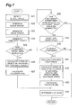
- FIG. 7 is a flowchart illustrating the operation of the collision determination device.
- the collision determination device repeatedly performs the process shown in FIG. 7 in a predetermined cycle.
- the speed sensor 11 detects the speed of the vehicle (vehicle speed) (Step S 21 ).
- the radar target generation unit 22 generates the radar target when the object is present in the detection range of the radar 13 (S 22 ).
- the image target generation unit 21 generates the image target when the object is present in the detection range of the stereo camera 12 (S 23 ).
- the composite target generation unit 23 generates the composite target when the radar target and the image target are collated with each other (S 24 ).
- the speed calculation unit 35 determines whether the composite target has been generated, that is, whether the object has been detected by both the sensors 12 and 13 (S 25 ).
- the speed calculation unit 35 calculates the speed of the object on the basis of the composite target (S 26 ). That is, the speed calculation unit 35 calculates the speed of the object on the basis of the distance to the object in the target information of the composite target. Then, the collision determination unit 36 divides the distance to the object by the speed of the object to calculate the collision time, on the basis of the target information of the composite target (S 27 ).
- the ECU 30 when it is determined in S 25 that the composite target has not been generated, the ECU 30 generates the composite target and determines whether only the image target has been generated (S 28 ). That is, the ECU 30 determines whether the object is detected only by the stereo camera 12 in the current processing cycle after it is detected by the radar 13 and the stereo camera 12 in the previous processing cycle.
- this corresponds to a case in which the pedestrian who crosses in front of the vehicle that is traveling deviates from the detection range of the radar 13 or a case in which the object has not been detected (lost) by the radar 13 for any reason.
- the calculation accuracy of the speed of the object based on image detection information is reduced.
- the image target generation unit 21 calculates the image speed (absolute speed) from the image detection information indicating the speed of the object (S 29 ).
- the stationary state determination unit 24 determines whether the object is stationary on the basis of the vehicle speed and the image speed (S 30 ). However, the process in S 30 may be omitted.
- the process in S 31 and the subsequent steps is performed if it is determined in S 30 that the object is stationary, and is not performed and ends if it is determined in S 30 that the object is not stationary.
- the speed calculation unit 35 calculates a distance coefficient corresponding to the distance to the object, using the target information of the image target (S 31 ).
- the speed calculation unit 35 calculates the speed (relative speed) of the object on the basis of the distance coefficient, the vehicle speed, and the image speed, using the above-mentioned Expression (1) (S 32 ).
- the collision determination unit 36 divides the distance to the object by the speed of the object to calculate the collision time, on the basis of the target information of the image target (S 33 ).
- the collision determination unit 36 determines a collision with the object on the basis of the collision time (S 34 ).
- the speed calculating device calculates the speed of the object, using the vehicle speed (moving body speed) and the image speed when the radar 13 does not detect the object after the composite target is generated. Therefore, the composite target and the detection result obtained by the image can be appropriately used according to the detection situation of the radar 13 to calculate the speed of the object.
- the speed of the object may be calculated using the vehicle speed (moving body speed) and the image speed. Therefore, the detection result obtained by the radar waves and the detection result obtained by the image may be appropriately used according to the detection situation of the object to calculate the speed of the object.
- the radar 13 does not detect the object after the composite target is generated, the speed of the object is calculated, using the vehicle speed (moving body speed) and the image speed. Therefore, the composite target and the detection result obtained by the image may be appropriately used according to the detection situation of the radar 13 to calculate the speed of the object.
- the speed of the object is calculated using the vehicle speed (moving body speed) and the image speed. Therefore, the detection result obtained by the radar waves and the detection result obtained by the image may be appropriately used according to the position of the object to calculate the speed of the object.
- the speed of the object is calculated using the vehicle speed (moving body speed) and the image speed. Therefore, the speed of the object may be accurately calculated using the vehicle speed (moving body speed).
- the case in which the composite target and the detection result obtained by the image are appropriately used according to the detection situation of the radar 13 to calculate the speed of the object has been described.
- this embodiment is similarly applied to a case in which the detection result obtained by the radar waves and the detection result obtained by the image are appropriately used according to the detection situation of the radar 13 to calculate the speed of the object.
- the above-described embodiments are the preferred embodiments of the speed calculating device, the speed calculating method, and the collision determination device according to the invention.
- the speed calculating device, the speed calculating method, and the collision determination device according to the invention are not limited to these embodiments.
- the speed calculating device, the speed calculating method, and the collision determination device according to the invention may be modified without departing from the scope and spirit of the invention described in the claims or they may be applied to other techniques.
- the functions of the image target generation unit 21 are implemented by the ECU 20 or the functions of the image target generation unit 21 and the radar target generation unit 22 are implemented by the ECU 30 .
- the functions of the image target generation unit 21 may be implemented by a single ECU, for example, an ECU for an image sensor and the functions of the radar target generation unit 22 may be implemented by a single ECU, for example, an ECU for a radar sensor.
- the speed of the object is calculated as the relative speed.
- the speed of the object may be calculated as an absolute speed.
- the collision determination device determines a collision with the object on the basis of the speed of the object calculated by the speed calculating device which calculates the speed of the object which is disposed around the vehicle, particularly, in front of the vehicle.
- the moving body is not limited to the vehicle and may be, for example, a ship, an airplane, or a flying object.
- the speed calculating device calculates the speed of the object in front of the moving body.
- the invention is not limited thereto and the speed calculating device may calculate the speed of the object in the traveling direction of the moving body and the collision determination device may determine a collision with the object on the basis of the speed of the object.
- an image sensor which captures the image of the front side of the moving body and detects an object from the captured image can be used to calculate the speed of the object in front of the moving body.
- at least two image sensors which capture the image of an object in front of the moving body and the image of an object on the rear side of the moving body and detect the objects from the captured images can be used to calculate the speed of the object in the traveling direction of the moving body.
Abstract
A speed calculating device calculates the speed of an object around a moving body and includes: an image detection unit that captures an image of the surroundings of the moving body and detects the object from the captured image; and a speed calculation unit that calculates the speed of the object, using a moving body speed indicating the speed of the moving body and an image speed, which indicates the speed of the object and is calculated from the image, at a ratio corresponding to a distance from the moving body to the object. The speed calculation unit calculates the speed of the object using the moving body speed and the image speed such that the ratio of the moving body speed increases as the distance to the object increases and the ratio of the image speed increases as the distance to the object decreases.
Description
- The present invention relates to a speed calculating device, a speed calculating method, and a collision determination device which calculate the speed of an object around a moving body.
- A technique has been known which calculates a distance to an object around a moving body and the speed of the object on the basis of image information in order to control the moving body. For example, Japanese Unexamined Patent Application Publication No. 2010-146494 discloses a device which switches a detection algorithm for short distance and a detection algorithm for long distance to detect an object in front of a vehicle, on the basis of whether the distance to the object is less than a threshold value.
- [Patent Literature 1] Japanese Unexamined Patent Application Publication No. 2010-146494
- However, the device calculates the speed of the object, using different algorithms in a situation in which the distance to the object is slightly less than the threshold value and a situation in which the distance to the object is slightly greater than the threshold value. Therefore, when there is a large difference in the calculation result of the speed of the object, the moving body is not smoothly controlled and the operator of the moving body feels discomfort.
- An object of the invention is to provide a speed calculating device, a speed calculating method, and a collision determination device which can accurately calculate the speed of an object around a moving body such that the operator of a moving body does not feel discomfort.
- According to an aspect of the invention, there is provided a speed calculating device that calculates a speed of an object around a moving body. The speed calculating device includes: an image detection unit that captures an image of the surroundings of the moving body and detects the object from the captured image; and a speed calculation unit that calculates the speed of the object, using a moving body speed indicating the speed of the moving body and an image speed, which indicates the speed of the object and is calculated from the image, at a ratio corresponding to a distance from the moving body to the object. The speed calculation unit calculates the speed of the object using the moving body speed and the image speed such that the ratio of the moving body speed increases as the distance to the object increases and the ratio of the image speed increases as the distance to the object decreases.
- According to this structure, the speed of the object is calculated using the moving body speed and the image speed at a ratio corresponding to the distance to the object. Therefore, it is possible to accurately calculate the speed of a distant object and the speed of a near object according to a change in the distance to the object. As the distance to the object increases, the accuracy of the image speed is reduced. Therefore, in particular, the ratio of the moving body speed increases in order to calculate the speed of the distant object and the ratio of the image speed increases in order to calculate the speed of the near object. As a result, it is possible to accurately calculate the speed of the object.
- The speed calculating device may further include a radar detection unit that detects the object using a radar wave. When the object is not detected by the radar detection unit, but is detected by the image detection unit, the speed calculation unit may calculate the speed of the object, using the moving body speed and the image speed. According to this structure, the detection result obtained by the radar wave and the detection result obtained by the image can be appropriately used according to the detection situation of the object to calculate the speed of the object.
- The speed calculating device may further include a composite target generation unit that generates a composite target of the object using a detection result obtained by the radar detection unit and a detection result obtained by the image detection unit. When the radar detection unit does not detect the object after the composite target is generated, the speed calculation unit may calculate the speed of the object, using the moving body speed and the image speed. According to this structure, the composite target and the detection result obtained by the image can be appropriately used according to the detection situation of the radar detection unit to calculate the speed of the object.
- The speed calculating device may further include a radar detection unit that detects the object using a radar wave. When the object is present outside a detection range of the radar detection unit and is present in a detection range of the image detection unit, the speed calculation unit may calculate the speed of the object, using the moving body speed and the image speed. According to this structure, the detection result obtained by the radar wave and the detection result obtained by the image can be appropriately used according to the position of the object to calculate the speed of the object.
- The speed calculating device may further include a stationary state determination unit that determines whether the object is stationary in a traveling direction of the moving body. When it is determined that the object is stationary, the speed calculation unit may calculate the speed of the object using the moving body speed and the image speed. According to this structure, it is possible to accurately calculate the speed of the object using the moving body speed.
- When the distance to the object is equal to or greater than an upper limit, the speed calculation unit may calculate the speed of the object using the moving body speed and the image speed such that the ratio of the moving body speed is 1 and the ratio of the image speed is 0. According to this structure, it is possible to accurately calculate the speed of a distant object using only the moving body speed.
- When the distance to the object is equal to or less than a lower limit, the speed calculation unit may calculate the speed of the object using the moving body speed and the image speed such that the ratio of the moving body speed is 0 and the ratio of the image speed is 1. According to this structure, it is possible to accurately calculate the speed of a near object using only the image speed.
- According to another aspect of the invention, there is provided a collision determination device including: the above-mentioned speed calculating device; and a collision determination unit that determines a collision with the object on the basis of the speed of the object calculated by the speed calculating device. According to this structure, it is possible to determine a collision with the object on the basis of the speeds of a near object and a distant object which are accurately calculated according to a change in the distance to the object.
- The speed calculating device may capture the image of the front side of the moving body, detect the object from the captured image, and calculate the speed of the object in front of the moving body.
- The speed calculating device may capture an image in the traveling direction of the moving body, detect the object from the captured image, and calculate the speed of the object in the traveling direction of the moving body.
- The moving body may be a vehicle or other moving bodies, such as a ship, an airplane, and a flying object.
- According to still another aspect of the invention, there is provided a speed calculating method that calculates a speed of an object around a moving body. The speed calculating method includes: capturing an image of the surroundings of the moving body and detecting the object from the captured image; and calculating the speed of the object, using a moving body speed indicating the speed of the moving body and an image speed, which indicates the speed of the object and is calculated from the image, such that the ratio of the moving body speed increases as the distance to the object increases and the ratio of the image speed increases as the distance to the object decreases. According to this structure, it is possible to accurately calculate the speeds of the near and distant objects according to a change in the distance to the object.
- According to the invention, it is possible to provide a speed calculating device, a speed calculating method, and a collision determination device which can accurately calculate the speed of an object around a vehicle such that the operator of a moving body does not feel discomfort.
-
FIG. 1 is a block diagram illustrating the structure of a collision determination device according to a first embodiment of the invention. -
FIG. 2 is a flowchart illustrating the operation of the collision determination device. -
FIG. 3 is a diagram illustrating an example of a distance coefficient map. -
FIG. 4 is a diagram illustrating the comparison between the calculation result of a collision time based on an image speed and the calculation result of a collision time based on a vehicle speed and the image speed. -
FIG. 5 is a block diagram illustrating the structure of a collision determination device according to a second embodiment of the invention. -
FIG. 6 is a diagram illustrating the detection ranges of a stereo camera and a radar. -
FIG. 7 is a flowchart illustrating the operation of the collision determination device. - Hereinafter, embodiments of the invention will be described in detail with reference to the accompanying drawings. In the description of the drawings, the same components are denoted by the same reference numerals and the description thereof will not be repeated.
- A speed calculating device, a speed calculating method, and a collision determination device according to embodiments of the invention will be described below. The speed calculating device and the speed calculating method calculate the speed of an object around a moving body. The collision determination device determines a collision with the object on the basis of the speed of the object calculated by the speed calculating device.
- Hereinafter, an embodiment will be described in which the moving body is a vehicle and the collision determination device determines a collision with an object on the basis of the speed of the object calculated by the speed calculating device that calculates the speed of the object around the vehicle, particularly, in front of the vehicle. However, the moving body is not limited to the vehicle and may be, for example, a ship, an airplane, or a flying object. In addition, the position where the speed of the object is calculated by the speed calculating device is not limited to the front side of the moving body and the speed calculating device may calculate the speed of the object in the traveling direction of the moving body. The collision determination device may determine a collision with the object on the basis of the speed of the object.
- The collision determination device according to a first embodiment of the invention will be described with reference to
FIGS. 1 to 4 . - The collision determination device is provided in the vehicle and determines a collision between the vehicle and the object using an image sensor. The collision determination device also functions as a speed calculating device which calculates the speed of the object using the image sensor. The object includes a moving body and a stationary body and is an obstacle which prevents the traveling of the vehicle, such as, a vehicle in front, an oncoming vehicle, a bicycle, a pedestrian, a parked vehicle, or a guardrail.
- First, the structure of the collision determination device will be described with reference to
FIG. 1 .FIG. 1 is a block diagram illustrating the structure of the collision determination device according to the first embodiment. As shown inFIG. 1 , the collision determination device includes aspeed sensor 11, astereo camera 12, and an electronic control unit (ECU) 20. - The
speed sensor 11 detects the speed of the vehicle. For example, a wheel speed sensor is used as thespeed sensor 11. Thespeed sensor 11 supplies the detected vehicle speed (absolute speed) to theECU 20. - The
stereo camera 12 functions as an image detection unit (image sensor) which captures the image of the front side of the vehicle and detects the object on the basis of the captured image. For example, a charge-coupled device (CCD) or a complementary metal-oxide semiconductor (CMOS) sensor is used as thestereo camera 12. Thestereo camera 12 includes a plurality of cameras and is provided on the front surface of the vehicle or in the cabin of the vehicle. Thestereo camera 12 supplies image detection information indicating the detection result of the object to theECU 20. In addition, a single camera may be used instead of thestereo camera 12. - The
ECU 20 includes an imagetarget generation unit 21, a stationarystate determination unit 24, aspeed calculation unit 25, and acollision determination unit 26. TheECU 20 includes, for example, a CPU, a ROM, and a RAM as main components. The CPU executes a program to implement the functions of the imagetarget generation unit 21, the stationarystate determination unit 24, thespeed calculation unit 25, and thecollision determination unit 26. TheECU 20 may be a single unit or it may include a plurality of units. - The image
target generation unit 21 generates an image target on the basis of the image detection information from thestereo camera 12. The image target has target information related to the distance to the object and the lateral position of the object which are calculated from the coordinates of the vehicle as a reference point. - The target information of the image target is calculated by the principle of triangulation, on the basis of the deviation between the image detection information items of the left and right cameras forming the
stereo camera 12, or it is calculated on the basis of the detection size and position of, for example, a number plate of the vehicle in front. The distance to the object indicates the distance from the vehicle (stereo camera 12) to the object in the traveling direction of the vehicle. The lateral position of the object indicates the distance from the vehicle (stereo camera 12) to the object in a direction perpendicular to the traveling direction of the vehicle. The lateral position of the image target also includes the range of the object detected from the image in the lateral direction, that is, information about the width of the object. When the target information is calculated, for example, a process of averaging the calculated values may be performed in order to reduce a calculation error. - The image
target generation unit 21 calculates an image speed (absolute speed) from the image detection information indicating the speed of the object. The image speed is calculated on the basis of the distance to the object and the vehicle speed, using the target information of the image target. The image speed is calculated on the basis of, for example, a change in the distance to the object in consecutive cycles. For example, the image speed is calculated by dividing the difference between the distance in a processing cycle i and the distance in a processing cycle i+1 by the interval of the processing cycle and reducing the vehicle speed from the divided value. When the image speed is calculated, for example, a process of averaging the calculated values in the consecutive processing cycles may be performed in order to reduce a calculation error. - The stationary
state determination unit 24 determines whether the object in front of the vehicle is stationary on the basis of the image speed. The stationary state of the object means that the speed (absolute speed) of the object in the traveling direction of the vehicle is 0 or substantially 0. For example, a pedestrian who crosses in front of the vehicle is assumed as the object. - The
speed calculation unit 25 calculates the speed (relative speed) of the object on the basis of the vehicle speed and the target information of the image target. Thespeed calculation unit 25 calculates the speed of the object, using the vehicle speed indicating the speed of the vehicle and the image speed indicating the speed of the object at a ratio corresponding to the distance to the object. Thespeed calculation unit 25 sets the ratio corresponding to the distance to the object such that the ratio of the vehicle speed increases as the distance to the object increases and the ratio of the image speed increases as the distance to the object decreases. In addition, thespeed calculation unit 25 may calculate the speed of the object using the vehicle speed and the image speed only when the object in front of the vehicle is stationary. - The
collision determination unit 26 determines a collision with the object on the basis of the speed of the object calculated by thespeed calculation unit 25. Thecollision determination unit 26 determines the possibility of a collision with the object on the basis of whether a collision time obtained by dividing the distance to the object by the speed of the object is less than a predetermined threshold value. For example, the determination result of the collision possibility is used to notify the driver of information or to control the braking or steering of the vehicle to support collision avoidance. - Next, the operation of the collision determination device will be described with reference to
FIGS. 2 and 3 .FIG. 2 is a flowchart illustrating the operation of the collision determination device. The collision determination device repeatedly performs the process shown inFIG. 2 in a predetermined cycle. - The
speed sensor 11 detects the vehicle speed (absolute speed) (Step S11). When there is an object in the detection range of thestereo camera 12, the imagetarget generation unit 21 generates an image target (S12). The imagetarget generation unit 21 calculates the image speed (absolute speed) from the image detection information indicating the speed of the object (S13). - The stationary
state determination unit 24 determines whether the object in front of the vehicle is stationary on the basis of the image speed (S14). This is because the accuracy of calculating the speed of the object on the basis of the vehicle speed can increase as the speed of the object in the traveling direction of the vehicle is reduced. However, the process in S14 may be omitted. - When the process in S14 is performed, the process in S15 and the subsequent steps is performed if it is determined in S14 that the object is stationary. If it is determined in S14 that the object is not stationary, the process is not performed and ends. In addition, it may be determined whether the object is a pedestrian who crosses a road on the basis of image recognition or it may be determined whether the object is present at the position of a crosswalk on the basis of image recognition or map information, instead of determining whether the object is stationary.
- The
speed calculation unit 25 calculates a distance coefficient corresponding to the distance to the object, using the target information of the image target (S15). The distance coefficient is a coefficient indicating the ratio (weighting) of the vehicle speed and the image speed used to calculate the speed of the object and is calculated using, for example, a distance coefficient map which will be described below. -
FIG. 3 is a diagram illustrating an example of the distance coefficient map. As shown inFIG. 3 , the distance coefficient map indicates the relationship between the distance to the object on the horizontal axis and the distance coefficient on the vertical axis. The lower limit T1 and upper limit Tu of the distance are set on the distance coefficient map. For example, the distance coefficient indicates the ratio (0 to 1) of the vehicle speed when the sum of the ratio of the vehicle speed and the ratio of the image speed is 1. In this example, the distance coefficient is set to “0” when the distance to the object is equal to or less than the lower limit T1, is set to “1” when the distance is equal to or greater than the upper limit Tu, and is set to a value between “0” and “1” when the distance is between the lower limit T1 and the upper limit Tu. In the example shown inFIG. 3 , the distance coefficient is set so as to monotonically increase between the lower limit T1 and the upper limit Tu. However, the distance coefficient may be set so as to increase in different manners. - Returning to
FIG. 2 , when the distance coefficient is calculated in S15, thespeed calculation unit 25 calculates the speed (relative speed) V of the object on the basis of the distance coefficient (p), the vehicle speed (V1), and the image speed (V2) (S16). The speed V of the object is calculated by the following expression: -
V=p·(−V1)+(1−p)·(V2−V1). [Expression (1)] - That is, the speed of the object is calculated using only the image speed when the distance to the object is equal to or less than the lower limit T1 and is calculated using only the vehicle speed when the distance is equal to or greater than the upper limit Tu. When the distance to the object is between the lower limit T1 and the upper limit Tu, the speed of the object is calculated using (with a larger weight) a higher ratio of the vehicle speed as the distance to the object increases and is calculated using (with a larger weight) a higher ratio of the image speed as the distance to the object decreases.
- When the speed of the object is calculated, the
collision determination unit 26 divides the distance to the object by the speed of the object to calculate a collision time (S17). Then, thecollision determination unit 26 determines a collision with the object on the basis of whether the collision time is less than a predetermined threshold value (S18). -
FIG. 4 is a diagram illustrating the comparison between the calculation result of the collision time based on the image speed and the calculation result of the collision time based on the vehicle speed and the image speed. The collision time based on the image speed is calculated by dividing the distance to the object by the speed of the object corresponding to the image speed and the collision time based on the vehicle speed and the image speed is calculated by dividing the distance to the object by the speed of the object calculated on the basis of the vehicle speed and the image speed. InFIG. 4 , the horizontal axis indicates the actually measured collision time and the vertical axis indicates the calculation result of the collision time. -
FIG. 4 shows a variation in the calculation result of the collision time due to a variation in the distance to the object. A dashed line indicates the range V1 of the variation in the calculation result based on the image speed and a solid line indicates the range V2 of the variation in the calculation result based on the vehicle speed and the image speed. As shown inFIG. 4 , the variation in the calculation result (V2) based on the vehicle speed and the image speed is reduced to about half the variation in the calculation result (V1) based on the image speed. Therefore, when the collision time is accurately calculated, it is possible to accurately determine the collision with the object. - As described above, according to the speed calculating device of the first embodiment, the speed of the object is calculated using the vehicle speed (moving body speed) and the image speed at a ratio corresponding to the distance to the object. Therefore, it is possible to accurately calculate the speeds of a near object and a distant object according to a change in the distance to the object. As the distance to the object increases, the accuracy of the image speed is reduced. Therefore, in particular, the ratio of the vehicle speed (moving body speed) increases in order to calculate the speed of the distant object and the ratio of the image speed increases in order to calculate the speed of the near object. As a result, it is possible to accurately calculate the speed of the object.
- When it is determined that the object is stationary, the speed of the object is calculated using the vehicle speed (moving body speed) and the image speed. Therefore, the speed of the object may be accurately calculated using the vehicle speed (moving body speed).
- According to the collision determination device of the embodiment of the invention, it is possible to determine a collision with the object on the basis of the speeds of a near object and a distant object which are accurately calculated according to a change in the distance to the object.
- According to the speed calculating method of the embodiment of the invention, the speed of the object is calculated using the vehicle speed (moving body speed) and the image speed at a ratio corresponding to the distance to the object. Therefore, it is possible to accurately calculate the speeds of a near object and a distant object according to a change in the distance to the object.
- Next, a collision determination device according to a second embodiment of the invention will be described with reference to
FIGS. 5 to 7 . In the second embodiment, the description of the same components as those in the first embodiment will not be repeated. - The collision determination device is provided in a vehicle and determines a collision between the vehicle and an object using a radar sensor and an image sensor. The collision determination device also functions as a speed calculating device which calculates the speed of the object using the radar sensor and the image sensor.
- First, the structure of the collision determination device will be described with reference to
FIGS. 5 and 6 .FIG. 5 is a block diagram illustrating the structure of the collision determination device according to the second embodiment. As shown inFIG. 5 , the collision determination device includes aspeed sensor 11, astereo camera 12, anECU 30, and aradar 13. The structure and function of thespeed sensor 11 and thestereo camera 12 are the same as those in the first embodiment and thus the description thereof will not be repeated. - The
radar 13 functions as a radar detection unit (radar sensor) which detects an object in front of the vehicle using radar waves, transmits radar waves (electromagnetic waves) to the front side of the vehicle, and receives radar waves reflected from the object. For example, a microwave radar, a millimeter-wave radar, an ultrasonic radar, or a laser radar is used as theradar 13. Theradar 13 supplies radar detection information indicating the detection result of the object to theECU 30. - The
ECU 30 includes an imagetarget generation unit 21, a stationarystate determination unit 24, aspeed calculation unit 25, acollision determination unit 26, a radartarget generation unit 22, and a compositetarget generation unit 23. TheECU 30 includes, for example, a CPU, a ROM, and a RAM as main components. The CPU executes a program to implement the functions of the imagetarget generation unit 21, the radartarget generation unit 22, the compositetarget generation unit 23, the stationarystate determination unit 24, thespeed calculation unit 35, and thecollision determination unit 36. The structure and function of the imagetarget generation unit 21 and the stationarystate determination unit 24 are the same as those in the first embodiment and thus the description thereof will not be repeated. - The radar
target generation unit 22 generates a radar target on the basis of the radar detection information from theradar 13. The radar target has target information related to the distance to the object and the lateral position of the object which are calculated from the coordinates of the vehicle as a reference. - The target information of the radar target is calculated on the basis of the radar detection information from the
radar 13. The distance to the object indicates the distance from the vehicle (radar 13) to the object in the traveling direction of the vehicle and is calculated on the basis of the time from the transmission of the radar wave from theradar 13 to the reception of the radar wave reflected from the object. - The lateral position of the object indicates the distance from the vehicle (radar 13) to the object in a direction perpendicular to the traveling direction of the vehicle and is calculated on the basis of the direction (angle) of the radar wave which is reflected from the objected and is then received. The lateral position of the radar target is information about the position of the object detected by the
radar 13 and does not include information about the width of the object. -
FIG. 6 is a diagram illustrating the detection ranges A1 and A2 of theradar 13 and thestereo camera 12. As shown inFIG. 6 , the detection range A1 of theradar 13 is narrower than the detection range A2 of thestereo camera 12. Therefore, a region which can be detected only by thestereo camera 12 and is arranged outside the detection range A1 of theradar 13 is present diagonally in front of the vehicle.FIG. 6 shows a target which moves from the detection ranges A1 and A2 of theradar 13 and thestereo camera 12 to the detection range A2 of thestereo camera 12. - The
radar 13 has low accuracy in the detection of the lateral position considering the width of the object and is not capable of detecting the width of the object. However, theradar 13 has high accuracy in the detection of the distance to the object. In contrast, thestereo camera 12 has low accuracy in the detection of the distance to the object but has high accuracy in the detection of the lateral position and width of the object. Therefore, the detection accuracy of an image speed which is calculated on the basis of the distance to the object in the target information of an image target is reduced as the distance to the object increases. - The composite
target generation unit 23 generates a composite target of the object, using the target information of the radar target and the image target, that is, the detection results of theradar 13 and thestereo camera 12. The composite target is generated by collating the two targets on the basis of the target information of the radar target and the image target. The two targets are collated with each other on the basis of the similarity between the target information items of the two targets, that is, the similarity between the distances to the object and the lateral positions. The composite target has target information related to the distance to the object and the lateral position (including the width) of the object. The target information of the composite target is based on the target information of the radar target and the image target and has higher accuracy than the target information of only the radar target or the target information of only the image target. - The
speed calculation unit 35 calculates the speed (relative speed) of the object on the basis of a vehicle speed and the target information of the composite target, the radar target, or the image target. When the composite target is generated, thespeed calculation unit 35 calculates the speed of the object on the basis of the target information of the composite target. In this case, the speed of the object is calculated by dividing the distance to the object in the target information of the composite target by the interval of the processing cycle. When only the radar target is generated, thespeed calculation unit 35 may calculate the speed of the object on the basis of the target information of the radar target. In this case, the speed of the object is calculated by dividing the distance to the object in the target information of the radar target by the interval of the processing cycle. - When only the image target is generated, the
speed calculation unit 35 calculates the speed of the object on the basis of the target information of the image target. In this case, thespeed calculation unit 35 calculates the speed of the object, using the vehicle speed indicating the speed of the vehicle and the image speed indicating the speed of the object at a ratio corresponding to the distance to the object. - The
collision determination unit 36 determines a collision with the object on the basis of the speed of the object calculated by thespeed calculation unit 35. Thecollision determination unit 36 determines the possibility of a collision with the object on the basis of whether a collision time obtained by dividing the distance to the object by the speed of the object is less than a predetermined threshold value. For example, the determination result of the possibility of the collision is used to notify the driver of information or to control the braking or steering of the vehicle. - Next, the operation of the collision determination device will be described with reference to
FIG. 7 .FIG. 7 is a flowchart illustrating the operation of the collision determination device. The collision determination device repeatedly performs the process shown inFIG. 7 in a predetermined cycle. - First, the
speed sensor 11 detects the speed of the vehicle (vehicle speed) (Step S21). The radartarget generation unit 22 generates the radar target when the object is present in the detection range of the radar 13 (S22). The imagetarget generation unit 21 generates the image target when the object is present in the detection range of the stereo camera 12 (S23). The compositetarget generation unit 23 generates the composite target when the radar target and the image target are collated with each other (S24). - The
speed calculation unit 35 determines whether the composite target has been generated, that is, whether the object has been detected by both thesensors 12 and 13 (S25). - When it is determined that the composite target has been generated, the
speed calculation unit 35 calculates the speed of the object on the basis of the composite target (S26). That is, thespeed calculation unit 35 calculates the speed of the object on the basis of the distance to the object in the target information of the composite target. Then, thecollision determination unit 36 divides the distance to the object by the speed of the object to calculate the collision time, on the basis of the target information of the composite target (S27). - On the other hand, when it is determined in S25 that the composite target has not been generated, the
ECU 30 generates the composite target and determines whether only the image target has been generated (S28). That is, theECU 30 determines whether the object is detected only by thestereo camera 12 in the current processing cycle after it is detected by theradar 13 and thestereo camera 12 in the previous processing cycle. - For example, this corresponds to a case in which the pedestrian who crosses in front of the vehicle that is traveling deviates from the detection range of the
radar 13 or a case in which the object has not been detected (lost) by theradar 13 for any reason. In this case, as the distance to the object increases, the calculation accuracy of the speed of the object based on image detection information is reduced. - When it is determined in S28 that only the image target has been generated, the image
target generation unit 21 calculates the image speed (absolute speed) from the image detection information indicating the speed of the object (S29). The stationarystate determination unit 24 determines whether the object is stationary on the basis of the vehicle speed and the image speed (S30). However, the process in S30 may be omitted. - When the process in S30 is performed, the process in S31 and the subsequent steps is performed if it is determined in S30 that the object is stationary, and is not performed and ends if it is determined in S30 that the object is not stationary. When it is not determined in S28 that only the image target has been generated, the process ends.
- As described with reference to
FIG. 3 , thespeed calculation unit 35 calculates a distance coefficient corresponding to the distance to the object, using the target information of the image target (S31). Thespeed calculation unit 35 calculates the speed (relative speed) of the object on the basis of the distance coefficient, the vehicle speed, and the image speed, using the above-mentioned Expression (1) (S32). - When the speed of the object is calculated, the
collision determination unit 36 divides the distance to the object by the speed of the object to calculate the collision time, on the basis of the target information of the image target (S33). When the collision time is calculated in S27 or S33, thecollision determination unit 36 determines a collision with the object on the basis of the collision time (S34). - As described above, the speed calculating device according to the second embodiment calculates the speed of the object, using the vehicle speed (moving body speed) and the image speed when the
radar 13 does not detect the object after the composite target is generated. Therefore, the composite target and the detection result obtained by the image can be appropriately used according to the detection situation of theradar 13 to calculate the speed of the object. - When the object is not detected by the
radar 13, but is detected by thestereo camera 12, the speed of the object may be calculated using the vehicle speed (moving body speed) and the image speed. Therefore, the detection result obtained by the radar waves and the detection result obtained by the image may be appropriately used according to the detection situation of the object to calculate the speed of the object. - When the
radar 13 does not detect the object after the composite target is generated, the speed of the object is calculated, using the vehicle speed (moving body speed) and the image speed. Therefore, the composite target and the detection result obtained by the image may be appropriately used according to the detection situation of theradar 13 to calculate the speed of the object. - When the object is present outside the detection range of the
radar 13 and is present in the detection range of thestereo camera 12, the speed of the object is calculated using the vehicle speed (moving body speed) and the image speed. Therefore, the detection result obtained by the radar waves and the detection result obtained by the image may be appropriately used according to the position of the object to calculate the speed of the object. - When it is determined that the object is stationary, the speed of the object is calculated using the vehicle speed (moving body speed) and the image speed. Therefore, the speed of the object may be accurately calculated using the vehicle speed (moving body speed).
- In the second embodiment, the case in which the composite target and the detection result obtained by the image are appropriately used according to the detection situation of the
radar 13 to calculate the speed of the object has been described. However, this embodiment is similarly applied to a case in which the detection result obtained by the radar waves and the detection result obtained by the image are appropriately used according to the detection situation of theradar 13 to calculate the speed of the object. - The above-described embodiments are the preferred embodiments of the speed calculating device, the speed calculating method, and the collision determination device according to the invention. However, the speed calculating device, the speed calculating method, and the collision determination device according to the invention are not limited to these embodiments. The speed calculating device, the speed calculating method, and the collision determination device according to the invention may be modified without departing from the scope and spirit of the invention described in the claims or they may be applied to other techniques.
- For example, in the above-described embodiments, the functions of the image
target generation unit 21 are implemented by theECU 20 or the functions of the imagetarget generation unit 21 and the radartarget generation unit 22 are implemented by theECU 30. However, the functions of the imagetarget generation unit 21 may be implemented by a single ECU, for example, an ECU for an image sensor and the functions of the radartarget generation unit 22 may be implemented by a single ECU, for example, an ECU for a radar sensor. - In the above-described embodiments, the speed of the object is calculated as the relative speed. However, the speed of the object may be calculated as an absolute speed.
- The speed calculating device, the speed calculating method, and the collision determination device according to the embodiments of the invention have been described above. In the above-described embodiments, the collision determination device determines a collision with the object on the basis of the speed of the object calculated by the speed calculating device which calculates the speed of the object which is disposed around the vehicle, particularly, in front of the vehicle.
- However, as described above, the moving body is not limited to the vehicle and may be, for example, a ship, an airplane, or a flying object. In the above-described embodiments, the speed calculating device calculates the speed of the object in front of the moving body. However, the invention is not limited thereto and the speed calculating device may calculate the speed of the object in the traveling direction of the moving body and the collision determination device may determine a collision with the object on the basis of the speed of the object.
- For example, an image sensor (image detection unit) which captures the image of the front side of the moving body and detects an object from the captured image can be used to calculate the speed of the object in front of the moving body. In addition, at least two image sensors which capture the image of an object in front of the moving body and the image of an object on the rear side of the moving body and detect the objects from the captured images can be used to calculate the speed of the object in the traveling direction of the moving body.
-
-
- 11: SPEED SENSOR
- 12: STEREO CAMERA
- 13: RADAR
- 20, 30: ECU
- 21: IMAGE TARGET GENERATION UNIT
- 22: RADAR TARGET GENERATION UNIT
- 23: COMPOSITE TARGET GENERATION UNIT
- 24: STATIONARY STATE DETERMINATION UNIT
- 25, 35: SPEED CALCULATION UNIT
- 26, 36: COLLISION DETERMINATION UNIT
Claims (12)
1. A speed calculating device that calculates a speed of an object around a moving body, comprising:
an image detection unit that captures an image of the surroundings of the moving body and detects the object from the captured image; and
a speed calculation unit that calculates the speed of the object, using a moving body speed indicating the speed of the moving body and an image speed, which indicates the speed of the object and is calculated from the image, at a ratio corresponding to a distance from the moving body to the object,
wherein the speed calculation unit calculates the speed of the object using the moving body speed and the image speed such that the ratio of the moving body speed increases as the distance to the object increases and the ratio of the image speed increases as the distance to the object decreases.
2. The speed calculating device according to claim 1 , further comprising:
a radar detection unit that detects the object using a radar wave,
wherein, when the object is not detected by the radar detection unit, but is detected by the image detection unit, the speed calculation unit calculates the speed of the object, using the moving body speed and the image speed.
3. The speed calculating device according to claim 2 , further comprising:
a composite target generation unit that generates a composite target of the object using a detection result obtained by the radar detection unit and a detection result obtained by the image detection unit,
wherein, when the radar detection unit does not detect the object after the composite target is generated, the speed calculation unit calculates the speed of the object, using the moving body speed and the image speed.
4. The speed calculating device according to claim 1 , further comprising:
a radar detection unit that detects the object using a radar wave,
wherein, when the object is present outside a detection range of the radar detection unit and is present in a detection range of the image detection unit, the speed calculation unit calculates the speed of the object, using the moving body speed and the image speed.
5. The speed calculating device according to claim 1 , further comprising:
a stationary state determination unit that determines whether the object is stationary in a traveling direction of the moving body,
wherein, when it is determined that the object is stationary, the speed calculation unit calculates the speed of the object using the moving body speed and the image speed.
6. The speed calculating device according to claim 1 ,
wherein, when the distance to the object is equal to or greater than an upper limit, the speed calculation unit calculates the speed of the object using the moving body speed and the image speed such that the ratio of the moving body speed is 1 and the ratio of the image speed is 0.
7. The speed calculating device according to claim 1 ,
wherein, when the distance to the object is equal to or less than a lower limit, the speed calculation unit calculates the speed of the object using the moving body speed and the image speed such that the ratio of the moving body speed is 0 and the ratio of the image speed is 1.
8. The speed calculating device according to claim 1 ,
wherein the speed calculating device calculates a speed of an object in front of the moving body and includes:
the image detection unit that captures an image of a front side of the moving body and detects the object from the captured image; and
the speed calculation unit that calculates the speed of the object, using the moving body speed indicating the speed of the moving body and the image speed, which indicates the speed of the object and is calculated from the image, at the ratio corresponding to the distance from the moving body to the object, and
wherein the speed calculation unit calculates the speed of the object using the moving body speed and the image speed such that the ratio of the moving body speed increases as the distance to the object increases and the ratio of the image speed increases as the distance to the object decreases.
9. The speed calculating device according to claim 1 ,
wherein the speed calculating device calculates a speed of an object in a traveling direction of the moving body and includes:
the image detection unit that captures an image in the traveling direction of the moving body and detects the object from the captured image; and
the speed calculation unit that calculates the speed of the object, using the moving body speed indicating the speed of the moving body and the image speed, which indicates the speed of the object and is calculated from the image, at the ratio corresponding to a distance from the moving body to the object, and
wherein the speed calculation unit calculates the speed of the object using the moving body speed and the image speed such that the ratio of the moving body speed increases as the distance to the object increases and the ratio of the image speed increases as the distance to the object decreases.
10. The speed calculating device according to claim 1 ,
wherein the moving body is a vehicle.
11. A collision determination device comprising:
the speed calculating device according to claim 1 ; and
a collision determination unit that determines a collision with the object on the basis of the speed of the object calculated by the speed calculating device.
12. A speed calculating method that calculates a speed of an object around a moving body, comprising:
capturing an image of the surroundings of the moving body and detecting the object from the captured image; and
calculating the speed of the object, using a moving body speed indicating the speed of the moving body and an image speed, which indicates the speed of the object and is calculated from the image, such that the ratio of the moving body speed increases as the distance to the object increases and the ratio of the image speed increases as the distance to the object decreases.
Applications Claiming Priority (1)
| Application Number | Priority Date | Filing Date | Title |
|---|---|---|---|
| PCT/JP2012/072362 WO2014033955A1 (en) | 2012-09-03 | 2012-09-03 | Speed calculating device and speed calculating method, and collision determination device |
Publications (2)
| Publication Number | Publication Date |
|---|---|
| US20150262375A1 true US20150262375A1 (en) | 2015-09-17 |
| US9905013B2 US9905013B2 (en) | 2018-02-27 |
Family
ID=50182799
Family Applications (1)
| Application Number | Title | Priority Date | Filing Date |
|---|---|---|---|
| US14/425,063 Active US9905013B2 (en) | 2012-09-03 | 2012-09-03 | Speed calculating device and speed calculating method, and collision determination device |
Country Status (5)
| Country | Link |
|---|---|
| US (1) | US9905013B2 (en) |
| EP (1) | EP2894618B1 (en) |
| JP (1) | JP6011625B2 (en) |
| CN (1) | CN104620297B (en) |
| WO (1) | WO2014033955A1 (en) |
Cited By (4)
| Publication number | Priority date | Publication date | Assignee | Title |
|---|---|---|---|---|
| US20150219761A1 (en) * | 2012-09-03 | 2015-08-06 | Toyota Jidosha Kabushiki Kaisha | Collision determination device and collision determination method |
| US20160137157A1 (en) * | 2013-07-08 | 2016-05-19 | Honda Motor Co., Ltd. | Object recognition device |
| US20200207340A1 (en) * | 2017-09-01 | 2020-07-02 | Murakami Corporation | Collision prediction device, collision prediction method, and program |
| US11091153B2 (en) * | 2016-05-19 | 2021-08-17 | Denso Corporation | Vehicle control apparatus and vehicle control method |
Families Citing this family (5)
| Publication number | Priority date | Publication date | Assignee | Title |
|---|---|---|---|---|
| US10317522B2 (en) * | 2016-03-01 | 2019-06-11 | GM Global Technology Operations LLC | Detecting long objects by sensor fusion |
| US20190039515A1 (en) * | 2017-08-01 | 2019-02-07 | Nanning Fugui Precision Industrial Co., Ltd. | System and method for warning against vehicular collisions when driving |
| CN110361560B (en) * | 2019-06-25 | 2021-10-26 | 中电科技(合肥)博微信息发展有限责任公司 | Ship navigation speed measuring method and device, terminal equipment and computer readable storage medium |
| CN110400463B (en) * | 2019-07-26 | 2020-09-04 | 合肥工业大学 | Safe driving early warning method based on optimal driving speed recommendation |
| US11531107B2 (en) | 2019-11-19 | 2022-12-20 | Volvo Car Corporation | Long range LIDAR-based speed estimation |
Citations (6)
| Publication number | Priority date | Publication date | Assignee | Title |
|---|---|---|---|---|
| US6311121B1 (en) * | 1998-01-19 | 2001-10-30 | Hitachi, Ltd. | Vehicle running control apparatus, vehicle running control method, and computer program product having the method stored therein |
| US6311122B1 (en) * | 1999-04-30 | 2001-10-30 | Nissan Motor Co., Ltd. | Vehicular velocity control apparatus to follow up preceding vehicle running ahead of vehicle |
| US20040061626A1 (en) * | 2002-09-30 | 2004-04-01 | Nissan Motor Co., Ltd. | Preceding-vehicle following control system |
| US20040090319A1 (en) * | 2002-11-12 | 2004-05-13 | Nissan Motor Co., Ltd. | Warning apparatus for vehicle |
| US20090143951A1 (en) * | 2007-11-16 | 2009-06-04 | Hitachi, Ltd. | Forward Collision Avoidance Assistance System |
| US20130110368A1 (en) * | 2011-10-26 | 2013-05-02 | GM Global Technology Operations LLC | Collision avoidance system and method of operating the same |
Family Cites Families (10)
| Publication number | Priority date | Publication date | Assignee | Title |
|---|---|---|---|---|
| JP2004217175A (en) * | 2003-01-17 | 2004-08-05 | Toyota Motor Corp | Vehicle-to-vehicle distance control device |
| JP3835438B2 (en) * | 2003-07-11 | 2006-10-18 | トヨタ自動車株式会社 | Vehicle control system for collision |
| JP4211809B2 (en) * | 2006-06-30 | 2009-01-21 | トヨタ自動車株式会社 | Object detection device |
| JP2008204281A (en) * | 2007-02-21 | 2008-09-04 | Nippon Soken Inc | Object detection device and inter-vehicle communication system |
| JP5145986B2 (en) * | 2008-02-05 | 2013-02-20 | 日産自動車株式会社 | Object detection apparatus and distance measuring method |
| JP2010020476A (en) * | 2008-07-09 | 2010-01-28 | Nissan Motor Co Ltd | Object detection device and object detection method |
| JP4815488B2 (en) | 2008-12-22 | 2011-11-16 | 本田技研工業株式会社 | Vehicle periphery monitoring device |
| JP2010204805A (en) * | 2009-03-02 | 2010-09-16 | Konica Minolta Holdings Inc | Periphery-monitoring device and method |
| US8610620B2 (en) * | 2009-12-08 | 2013-12-17 | Toyota Jidosha Kabushiki Kaisha | Object detecting apparatus and object detecting method |
| CN102542843A (en) * | 2010-12-07 | 2012-07-04 | 比亚迪股份有限公司 | Early warning method for preventing vehicle collision and device |
-
2012
- 2012-09-03 EP EP12883817.4A patent/EP2894618B1/en active Active
- 2012-09-03 JP JP2014532715A patent/JP6011625B2/en active Active
- 2012-09-03 US US14/425,063 patent/US9905013B2/en active Active
- 2012-09-03 WO PCT/JP2012/072362 patent/WO2014033955A1/en active Application Filing
- 2012-09-03 CN CN201280075553.2A patent/CN104620297B/en active Active
Patent Citations (6)
| Publication number | Priority date | Publication date | Assignee | Title |
|---|---|---|---|---|
| US6311121B1 (en) * | 1998-01-19 | 2001-10-30 | Hitachi, Ltd. | Vehicle running control apparatus, vehicle running control method, and computer program product having the method stored therein |
| US6311122B1 (en) * | 1999-04-30 | 2001-10-30 | Nissan Motor Co., Ltd. | Vehicular velocity control apparatus to follow up preceding vehicle running ahead of vehicle |
| US20040061626A1 (en) * | 2002-09-30 | 2004-04-01 | Nissan Motor Co., Ltd. | Preceding-vehicle following control system |
| US20040090319A1 (en) * | 2002-11-12 | 2004-05-13 | Nissan Motor Co., Ltd. | Warning apparatus for vehicle |
| US20090143951A1 (en) * | 2007-11-16 | 2009-06-04 | Hitachi, Ltd. | Forward Collision Avoidance Assistance System |
| US20130110368A1 (en) * | 2011-10-26 | 2013-05-02 | GM Global Technology Operations LLC | Collision avoidance system and method of operating the same |
Cited By (7)
| Publication number | Priority date | Publication date | Assignee | Title |
|---|---|---|---|---|
| US20150219761A1 (en) * | 2012-09-03 | 2015-08-06 | Toyota Jidosha Kabushiki Kaisha | Collision determination device and collision determination method |
| US9470790B2 (en) * | 2012-09-03 | 2016-10-18 | Toyota Jidosha Kabushiki Kaisha | Collision determination device and collision determination method |
| US20160137157A1 (en) * | 2013-07-08 | 2016-05-19 | Honda Motor Co., Ltd. | Object recognition device |
| US9582886B2 (en) * | 2013-07-08 | 2017-02-28 | Honda Motor Co., Ltd. | Object recognition device |
| US11091153B2 (en) * | 2016-05-19 | 2021-08-17 | Denso Corporation | Vehicle control apparatus and vehicle control method |
| US20200207340A1 (en) * | 2017-09-01 | 2020-07-02 | Murakami Corporation | Collision prediction device, collision prediction method, and program |
| US11472404B2 (en) * | 2017-09-01 | 2022-10-18 | Murakami Corporation | Collision prediction device, collision prediction method, and program |
Also Published As
| Publication number | Publication date |
|---|---|
| JPWO2014033955A1 (en) | 2016-08-08 |
| EP2894618A4 (en) | 2015-07-15 |
| WO2014033955A1 (en) | 2014-03-06 |
| EP2894618B1 (en) | 2016-10-26 |
| CN104620297B (en) | 2017-03-22 |
| CN104620297A (en) | 2015-05-13 |
| JP6011625B2 (en) | 2016-10-19 |
| US9905013B2 (en) | 2018-02-27 |
| EP2894618A1 (en) | 2015-07-15 |
Similar Documents
| Publication | Publication Date | Title |
|---|---|---|
| US9905013B2 (en) | Speed calculating device and speed calculating method, and collision determination device | |
| US9405006B2 (en) | Collision determination device and collision determination method | |
| US9470790B2 (en) | Collision determination device and collision determination method | |
| JP6536521B2 (en) | Object detection apparatus and object detection method | |
| US10836388B2 (en) | Vehicle control method and apparatus | |
| US10559205B2 (en) | Object existence determination method and apparatus | |
| CN109891262B (en) | Object detecting device | |
| US10668919B2 (en) | Object detection apparatus and object detection method | |
| US9666077B2 (en) | Collision determination device and collision determination method | |
| US10527719B2 (en) | Object detection apparatus and object detection method | |
| JP6535194B2 (en) | Vehicle control device and vehicle control method | |
| JP2016192166A (en) | Vehicle control device and vehicle control method | |
| US20170217395A1 (en) | Drive assist apparatus | |
| JP2019052920A (en) | Object detector, object detection method and vehicle control system | |
| JP6429360B2 (en) | Object detection device | |
| JP6432538B2 (en) | Collision prediction device | |
| US10857998B2 (en) | Vehicle control device operating safety device based on object position | |
| WO2014033958A1 (en) | Collision determination device and collision determination method |
Legal Events
| Date | Code | Title | Description |
|---|---|---|---|
| AS | Assignment |
Owner name: TOYOTA JIDOSHA KABUSHIKI KAISHA, JAPAN Free format text: ASSIGNMENT OF ASSIGNORS INTEREST;ASSIGNOR:INOMATA, RYO;REEL/FRAME:035066/0673 Effective date: 20150220 |
|
| STCF | Information on status: patent grant |
Free format text: PATENTED CASE |
|
| MAFP | Maintenance fee payment |
Free format text: PAYMENT OF MAINTENANCE FEE, 4TH YEAR, LARGE ENTITY (ORIGINAL EVENT CODE: M1551); ENTITY STATUS OF PATENT OWNER: LARGE ENTITY Year of fee payment: 4 |