US20150245405A1 - Method of Enhanced Connection Recovery and Loss-Less DATA Recovery - Google Patents
Method of Enhanced Connection Recovery and Loss-Less DATA Recovery Download PDFInfo
- Publication number
- US20150245405A1 US20150245405A1 US14/709,479 US201514709479A US2015245405A1 US 20150245405 A1 US20150245405 A1 US 20150245405A1 US 201514709479 A US201514709479 A US 201514709479A US 2015245405 A1 US2015245405 A1 US 2015245405A1
- Authority
- US
- United States
- Prior art keywords
- base station
- rrc
- cell
- rlf
- request
- Prior art date
- Legal status (The legal status is an assumption and is not a legal conclusion. Google has not performed a legal analysis and makes no representation as to the accuracy of the status listed.)
- Granted
Links
- 238000000034 method Methods 0.000 title claims abstract description 96
- 238000011084 recovery Methods 0.000 title claims abstract description 69
- 230000004044 response Effects 0.000 claims description 18
- 238000004891 communication Methods 0.000 claims description 4
- 238000010295 mobile communication Methods 0.000 abstract description 28
- 238000005259 measurement Methods 0.000 description 16
- 238000012913 prioritisation Methods 0.000 description 15
- 230000007246 mechanism Effects 0.000 description 12
- 230000001960 triggered effect Effects 0.000 description 11
- 230000008569 process Effects 0.000 description 8
- 238000007726 management method Methods 0.000 description 7
- 238000010586 diagram Methods 0.000 description 4
- 230000006870 function Effects 0.000 description 4
- 101100490659 Arabidopsis thaliana AGP17 gene Proteins 0.000 description 3
- 101001055444 Homo sapiens Mediator of RNA polymerase II transcription subunit 20 Proteins 0.000 description 3
- 102100026165 Mediator of RNA polymerase II transcription subunit 20 Human genes 0.000 description 3
- 101100049938 Neurospora crassa (strain ATCC 24698 / 74-OR23-1A / CBS 708.71 / DSM 1257 / FGSC 987) exr-1 gene Proteins 0.000 description 3
- 108091005487 SCARB1 Proteins 0.000 description 3
- 102100037118 Scavenger receptor class B member 1 Human genes 0.000 description 3
- 238000011156 evaluation Methods 0.000 description 3
- 238000012544 monitoring process Methods 0.000 description 3
- 101150101384 rat1 gene Proteins 0.000 description 3
- 238000010187 selection method Methods 0.000 description 3
- 238000012546 transfer Methods 0.000 description 3
- 230000008901 benefit Effects 0.000 description 2
- 230000001419 dependent effect Effects 0.000 description 2
- 238000001514 detection method Methods 0.000 description 2
- 238000005516 engineering process Methods 0.000 description 2
- 230000009471 action Effects 0.000 description 1
- 230000006978 adaptation Effects 0.000 description 1
- 230000005540 biological transmission Effects 0.000 description 1
- 230000004069 differentiation Effects 0.000 description 1
- 230000000694 effects Effects 0.000 description 1
- 230000006872 improvement Effects 0.000 description 1
- 230000007774 longterm Effects 0.000 description 1
- 239000000203 mixture Substances 0.000 description 1
- 238000012986 modification Methods 0.000 description 1
- 230000004048 modification Effects 0.000 description 1
- 229910052704 radon Inorganic materials 0.000 description 1
- SYUHGPGVQRZVTB-UHFFFAOYSA-N radon atom Chemical compound [Rn] SYUHGPGVQRZVTB-UHFFFAOYSA-N 0.000 description 1
- 230000011664 signaling Effects 0.000 description 1
- 238000001228 spectrum Methods 0.000 description 1
Images


Classifications
-
- H04W76/027—
-
- H—ELECTRICITY
- H04—ELECTRIC COMMUNICATION TECHNIQUE
- H04W—WIRELESS COMMUNICATION NETWORKS
- H04W76/00—Connection management
- H04W76/10—Connection setup
- H04W76/19—Connection re-establishment
-
- H—ELECTRICITY
- H04—ELECTRIC COMMUNICATION TECHNIQUE
- H04W—WIRELESS COMMUNICATION NETWORKS
- H04W36/00—Hand-off or reselection arrangements
- H04W36/0005—Control or signalling for completing the hand-off
- H04W36/0055—Transmission or use of information for re-establishing the radio link
- H04W36/0061—Transmission or use of information for re-establishing the radio link of neighbour cell information
-
- H—ELECTRICITY
- H04—ELECTRIC COMMUNICATION TECHNIQUE
- H04W—WIRELESS COMMUNICATION NETWORKS
- H04W36/00—Hand-off or reselection arrangements
- H04W36/0005—Control or signalling for completing the hand-off
- H04W36/0055—Transmission or use of information for re-establishing the radio link
- H04W36/0064—Transmission or use of information for re-establishing the radio link of control information between different access points
-
- H—ELECTRICITY
- H04—ELECTRIC COMMUNICATION TECHNIQUE
- H04W—WIRELESS COMMUNICATION NETWORKS
- H04W36/00—Hand-off or reselection arrangements
- H04W36/0005—Control or signalling for completing the hand-off
- H04W36/0055—Transmission or use of information for re-establishing the radio link
- H04W36/0072—Transmission or use of information for re-establishing the radio link of resource information of target access point
- H04W36/00725—Random access channel [RACH]-less handover
-
- H—ELECTRICITY
- H04—ELECTRIC COMMUNICATION TECHNIQUE
- H04W—WIRELESS COMMUNICATION NETWORKS
- H04W36/00—Hand-off or reselection arrangements
- H04W36/08—Reselecting an access point
-
- H—ELECTRICITY
- H04—ELECTRIC COMMUNICATION TECHNIQUE
- H04W—WIRELESS COMMUNICATION NETWORKS
- H04W36/00—Hand-off or reselection arrangements
- H04W36/24—Reselection being triggered by specific parameters
-
- H—ELECTRICITY
- H04—ELECTRIC COMMUNICATION TECHNIQUE
- H04W—WIRELESS COMMUNICATION NETWORKS
- H04W36/00—Hand-off or reselection arrangements
- H04W36/24—Reselection being triggered by specific parameters
- H04W36/249—Reselection being triggered by specific parameters according to timing information
-
- H—ELECTRICITY
- H04—ELECTRIC COMMUNICATION TECHNIQUE
- H04W—WIRELESS COMMUNICATION NETWORKS
- H04W40/00—Communication routing or communication path finding
- H04W40/34—Modification of an existing route
- H04W40/36—Modification of an existing route due to handover
-
- H—ELECTRICITY
- H04—ELECTRIC COMMUNICATION TECHNIQUE
- H04W—WIRELESS COMMUNICATION NETWORKS
- H04W48/00—Access restriction; Network selection; Access point selection
- H04W48/17—Selecting a data network PoA [Point of Attachment]
-
- H04W76/028—
-
- H—ELECTRICITY
- H04—ELECTRIC COMMUNICATION TECHNIQUE
- H04W—WIRELESS COMMUNICATION NETWORKS
- H04W76/00—Connection management
- H04W76/10—Connection setup
- H04W76/18—Management of setup rejection or failure
-
- H—ELECTRICITY
- H04—ELECTRIC COMMUNICATION TECHNIQUE
- H04W—WIRELESS COMMUNICATION NETWORKS
- H04W36/00—Hand-off or reselection arrangements
- H04W36/0005—Control or signalling for completing the hand-off
- H04W36/0011—Control or signalling for completing the hand-off for data sessions of end-to-end connection
- H04W36/0033—Control or signalling for completing the hand-off for data sessions of end-to-end connection with transfer of context information
-
- H—ELECTRICITY
- H04—ELECTRIC COMMUNICATION TECHNIQUE
- H04W—WIRELESS COMMUNICATION NETWORKS
- H04W36/00—Hand-off or reselection arrangements
- H04W36/0005—Control or signalling for completing the hand-off
- H04W36/0055—Transmission or use of information for re-establishing the radio link
Definitions
- the disclosed embodiments relate generally to enhanced connection recovery in mobile communication network, and, more particularly, to enhanced connection recovery upon lost RRC connection due to radio link failure (RLF) or handover failure (HOF).
- RLF radio link failure
- HAF handover failure
- an evolved universal terrestrial radio access network includes a plurality of base stations, e.g., evolved Node-Bs (eNBs) communicating with a plurality of mobile stations referred as user equipments (UEs) over established radio resource control (RRC) connections.
- Radio link monitoring is a mechanism for a UE to monitor the quality of a downlink (DL) channel of its serving cell for determining if the radio link is good enough to continue transmission.
- the UE measures cell-specific reference signal (CRS) to detect the downlink radio link quality for the serving cell.
- CRS cell-specific reference signal
- the UE also compares the estimated DL quality to thresholds (e.g., Q OUT and Q IN ) for determining if the link between the serving cell and the UE is good enough or not.
- the UE declares radio link failure (RLF) upon the occurrences of physical layer problems based on N310/N311/T310 mechanism, random access problem indication from MAC layer, and indication from RLC layer that the maximum number of retransmission has been reached. Once RLF is detected, the UE gathers and stores RLF information and attempts to restore the RRC connection by performing an RRC reestablishment procedure.
- RLF radio link failure
- each UE For mobility management in LTE systems, each UE needs to periodically measure the received reference signal power and the qualities of the serving cell and neighbor cells and reports measurement results to its serving eNB for potential handover or cell reselection. Measurements, such as Reference signal received power (RSRP) and/or Reference signal received quality (RSRQ) of an LTE cell, are used to to rank among the different cells for the purpose of mobility management. Properly managed handover can prevent loss of connection. In practice, however, handover failure (HOF) often occurs due to various reasons such as UE signaling problems and UE measurement configuration problems. Typically, a radio link failure or handover failure indicates too early handover, too late handover, or handover to a wrong cell. After the RLF/HOF event, the UE will attempt an RRC reestablishment procedure to restore the RRC connection.
- RSRP Reference signal received power
- RSRQ Reference signal received quality
- the UE When performing RRC reestablishment, the UE releases current RRC configuration and performs cell selection.
- the prerequisite of a successful RRC reestablishment procedure is that the selected cell for RRC reestablishment has UE context. If the UE fails to restore the RRC connection, then the UE enters RRC idle mode and tries to camp on a cell via a non-access Stratum (NAS) recovery procedure.
- NAS non-access Stratum
- the UE may indicate the availability of the RLF report to eNB and report the RLF/HOF information to eNB upon request after successful RRC connection reestablishment or RRC connection setup. Based on the RLF report, possible corrective action may be applied by the network to prevent future connection failures.
- LTE-A LTE-Advanced
- HetNet heterogeneous network
- smarter resource coordination among base stations, better base station selection strategies and more advance techniques for efficient interference management can provide substantial gains in throughput and user experience as compared to a conventional homogeneous network.
- HOF/RLF rate would increase.
- HOF/RLF may occur due to imprecise pico cell measurement or not enough time for pico-macro handover. It is thus desirable to improve the connection recovery procedure to reduce outrage time and to reduce data loss during the connection recovery.
- a UE first establishes an RRC connection in a source cell in a mobile communication network. Later on, the UE detects a failure event and starts an RRC reestablishment procedure in a target cell to restore the RRC connection.
- the enhance connection recovery may be performed from UE/radio access perspective or from network perspective. From UE/radio access perspective, the enhanced connection recovery may be applied to reduce the outage time in the source cell (e.g., via fast RLF) or to reduce the outage time in the target cell (e.g., via enhance cell selection and multi-RAT registration). From network perspective, the enhanced connection recovery may be applied to reduce the outage time in the target cell (e.g., via fast NAS recovery and context fetch), or to reduce data loss during the recovery (e.g., via loss-less data recovery).
- a fast RLF process is applied to reduce the outage time in the serving cell.
- a new timer e.g., T310a
- RRC reestablishment is performed when the new timer expires.
- the UE initiates RRC reestablishment before T310 timer expires if a candidate cell (e.g., a neighbor cell with better radio link quality than the serving cell) is identified by the UE itself.
- an enhanced cell selection mechanism based on cell prioritization information is applied to reduce the outage time in the target cell.
- the priority for cell selection is based on frequency layers with good mobility coverage or based on intra-frequency cells with good mobility coverage.
- the cell prioritization information may be carried by broadcasting or unicasting and PCI ranging mechanism may be used to identify the mobility cells.
- multi-RAT registration is applied to steer cell selection.
- the cell prioritization is selectively applied to UEs with high mobility state.
- a fast NAS recovery process is applied to reduce the outage time in the target cell.
- a NAS service request is triggered by the RRC reestablishment request.
- the target base station inquires UE context from an MME via S1 interface upon receiving the NAS service request. Because the NAS service request is triggered earlier, the target eNB can obtain the UE context information quicker and thus reduce the outage time in the target cell.
- context fetching is used to reduce the outage time in the target cell.
- the target eNB sends an RLF indication to the source eNB via X2 interface, and the RLF indication comprises a UE context request.
- the source eNB sends the UE context information to the target eNB.
- RRC reestablishment is successfully completed and the outage time in the target cell is reduced.
- a loss-less reestablishment procedure is proposed to reduce data loss during the connection recovery.
- the target eNB sends an RLF indication to the source eNB, and the RLF indication comprises data-forwarding request.
- the source eNB sends PDCP SN status and U-plane data to the target eNB. The PDCP operation is thus resumed without data loss.
- FIG. 1 illustrates a mobile communication network with enhanced connection recovery in accordance with one novel aspect.
- FIG. 2 is a diagram that illustrates different embodiments of enhanced connection recovery in accordance with one novel aspect.
- FIG. 3 is a simplified block diagram of a UE and an eNodeB in accordance with one novel aspect.
- FIG. 4 illustrates enhanced connection recovery from radio access network perspective.
- FIG. 5 illustrates a fast RLF procedure in accordance with one novel aspect.
- FIG. 6 illustrates one embodiment of fast RLF involving a new T310a timer.
- FIG. 7 illustrates one embodiment of enhanced cell selection based on cell prioritization.
- FIG. 8 illustrates one embodiment of enhanced cell selection with multi-RAT registration.
- FIG. 9 is a flow chart of a method of fast radio link failure procedure.
- FIG. 10 is a flow chart of a method of enhanced cell selection with prioritization.
- FIG. 11 illustrates a first embodiment of RRC reestablishment procedure with fast NAS recovery.
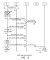
- FIG. 12 illustrates a second embodiment of RRC reestablishment procedure with fast NAS recovery.
- FIG. 13 illustrates one embodiment of RRC reestablishment procedure with context fetching.
- FIG. 14 illustrates one embodiment of loss-less RRC reestablishment procedure.
- FIG. 15 is a flow chart of a method of fast NAS recovery in target cell from UE perspective.
- FIG. 16 is a flow chart of a method of fast NAS recovery in target cell from BS perspective.
- FIG. 17 is a flow chart of a method of RRC reestablishment procedure with context fetching.
- FIG. 18 is a flow chart of a method of loss-less RRC reestablishment procedure.
- FIG. 1 illustrates a mobile communication network 100 with enhanced connection recovery in accordance with one novel aspect.
- Mobile communication network 100 comprises a user equipment UE 101 , a radio access network (RAN) 108 having a first base station eNB 102 , a second base station eNB 103 , a packet core network (CN) 109 having a mobility management entity MME 104 , a serving gateway SGW 105 , and a packet data network (PDN) gateway PGW 106 , and Internet 107 .
- the base stations communicate with each other via the X2 interface, and each base station communicates with MME 104 via the S1 interface.
- UE 101 may access Internet 107 via the radio access network RAN 108 and the packet core network CN 109 .
- UE 101 first establishes a radio resource control (RRC) connection with its serving base station eNB 102 as a source cell. Later on, UE 101 detects a failure event such as a radio link failure (RLF) or a handover failure (HOF). UE 101 then performs an RRC reestablishment procedure to restore the RRC connection. For example, UE 101 may select a target cell with the target base station eNB 103 and performs the RRC reestablishment. If the RRC reestablishment fails, then UE 101 may go to RRC idle mode and starts non-access stratum (NAS) recovery to establish a new RRC connection. During the connection recovery process, the RRC connection is interrupted.
- RRC radio resource control
- connection outage time The interruption time is referred to as connection outage time.
- an enhanced connection recovery process 111 e.g., that involves UE, RAN, X2 interface and S1 interface is applied to reduce the outage time in the source/target cell and to reduce the data loss during the connection recovery.
- FIG. 2 is a diagram that illustrates different embodiments of enhanced connection recovery in accordance with one novel aspect.
- an enhanced connection recovery process 201 may be performed from UE/radio access perspective (as depicted by box 211 ) or from network perspective (as depicted by box 221 ).
- the enhanced connection recovery may be applied to reduce the outage time in the source cell (as depicted by box 231 ), or to reduce the outage time in the target cell (as depicted by box 232 ).
- a fast RLF procedure 241 may be used.
- enhanced cell selection 242 may be used.
- IRAT multi registration 243 may be applied to reduce outage time in the target cell.
- the enhanced connection recovery may be applied to reduce the outage time in the target cell (as depicted by box 232 ), or to reduce data loss (as depicted by box 233 ).
- a novel fast NAS recovery 244 may be used.
- a novel context fetching 245 may be used.
- a loss-less recovery mechanism 246 may be applied via the X2 interface.
- FIG. 3 is a simplified block diagram of a user equipment UE 301 and a base station eNodeB 302 in accordance with one novel aspect.
- User equipment UE 301 comprises memory 311 having program codes 314 , a processor 312 , a transceiver 313 coupled to an antenna module 319 .
- User equipment UE 301 also comprises various function modules including a measurement module 315 that performs various measurements based on measurement configurations, an RLM/RLF module 316 that performs radio link monitoring, radio link failure detection and handling, a cell selection module 317 that performs cell selection for connection establishment and recovery, and an RRC connection management module 318 that performs RRC connection setup procedures and maintains RRC connection.
- base station eNodeB 302 comprises memory 321 having program codes 324 , a processor 322 , a transceiver 323 coupled to an antenna module 329 .
- Base station eNodeB 302 also comprises various function modules including a configuration module 325 that provides various configuration to UE 301 , an S1 interface module 326 that manages communication with an MME in the core network, an X2 interface module 327 that manages communication with other base stations, and an RRC connection management module 328 that performs RRC connection setup procedures and maintains RRC connection.
- the different modules are function modules that can be implemented by software, firmware, hardware, or any combination thereof.
- the function modules when executed by the processors (e.g., via executing program codes 314 and 324 ), allow UE 301 and eNB 302 to perform enhanced connection recovery upon detecting a connection failure event.
- RLM/RLF module 316 detects a radio link problem and invokes a fast RLF mechanism to reduce the outage time in the source cell.
- cell selection module 317 performs enhanced cell selection upon a failure event to reduce the outage time in the target cell.
- context fetching or fast NAS recovery is performed by eNB 302 via the X2/S1 interface module 326 / 327 to reduce the outage time in the target cell.
- loss-less RRC reestablishment is performed by eNB 302 via the X2 interface module 327 to reduce data loss during the connection recovery.
- FIG. 4 illustrates enhanced connection recovery from UE/radio access network perspective in a mobile communication network 400 .
- Mobile communication network 400 comprises a UE 401 , a serving eNB 402 (for connection in a source cell), and a target eNB 403 (for connection in a target cell).
- connection recovery may be enhanced by a fast RLF procedure to reduce outage time in the source cell and by an enhanced cell selection mechanism to reduce outage time in the target cell.
- UE 401 establishes an RRC connection with eNB 402 in the source cell. Later on, UE 401 detects a possible radio link problem, e.g., link quality is lower than a threshold Q OUT .
- a possible radio link problem e.g., link quality is lower than a threshold Q OUT .
- a T310 timer is then started and RLF is detected when T310 timer expires.
- UE 401 selects a cell and tries to restore the RRC connection. This is an eNB-controlled mechanism and the timer value is configured by the network.
- the legacy RLF procedure with T310 timer may not provide enough flexibility for better performance, especially with respect to small cells. For example, a small cell may not provide good coverage of the coverage layer and long RLF detection time may not be suitable. Under those cases, the legacy RLF solution would lead to frequent RRC reestablishments.
- UE 401 initiates a fast RLF procedure in step 412 , during which the evaluation of RLF is not only dependent on the source cell timer and filter, but also dependent on the signal strength and/or quality of the selected reestablishment cell. For example, if there is an identified reestablishment cell (e.g., implicitly or explicitly), and the reestablishment cell is radio-wise “good enough”, then RLF evaluation is shortened and the UE goes to the reestablishment cell.
- UE 401 performs RRC reestablishment with eNB 403 in the target cell. The RRC reestablishment may fail if the target eNB 403 does not have UE context information.
- step 414 UE 401 goes to RRC idle mode and initiates NAS recovery when RRC reestablishment fails.
- step 415 UE 401 performs RRC connection setup with eNB 403 in the selected target cell.
- the cell selection in step 414 is performed when RRC reestablishment failure occurs.
- UE follows legacy cell selection method to select a suitable cell.
- HetNet deployment e.g., macro-pico
- there might be frequent RRC reestablishment if there is no differentiation among cells and frequency layers with respect to cell selection.
- a high-mobility UE may move out of the coverage of a pico cell easily. In such case, if UE can reestablish an RRC connection with a macro cell, then it is expected to have less frequent RRC connection reestablishment.
- UE 401 applies an enhanced cell selection method in step 414 .
- UE 401 selects the target cell with priority.
- the priority may be assigned based on frequency layers or based on intra-frequency cells.
- one frequency layer is configured as a mobility layer.
- UE selects a cell in the mobility layer with priority when reestablishment fails.
- cells with larger coverage such as macro cells are configured as mobility cells.
- UE selects one of the macro cells with priority when reestablishment fails.
- UE with high moving speed should re-connect to the coverage layer, which is indicated by eNB via broadcasting or unicasting. For example, if UE mobility state is higher than a threshold, then UE only re-establishes to the coverage layer.
- FIG. 5 illustrates a fast RLF procedure in accordance with one novel aspect in a mobile communication network 500 .
- Mobile communication network 500 comprises a UE 501 , a serving eNB 502 (for connection in a source cell), and a target eNB 503 (for connection in a target cell).
- UE 501 establishes an RRC connection with eNB 502 in the source cell.
- UE 501 performs radio link monitoring and measures radio signal strength/quality.
- UE 501 detects a possible radio link problem, e.g., link quality is lower than a threshold Q OUT . Based on the legacy RLF procedure, UE 501 starts T310 timer.
- UE 501 In addition to the legacy RLF that relies on network-controlled source cell timer and filter, UE 501 also initiates a fast RLF procedure, which is a UE-controlled mechanism as a backup option of the legacy RLF. In one embodiment, the fast RLF only kicks off when prepared HO is likely to fail. For example, UE 501 sends a measurement report to eNB 502 in step 514 , and eNB 502 makes certain mobility decision in step 515 . Based on the mobile decision, eNB 502 sends an HO command to UE 501 in step 516 . UE 501 , however, fails to receive the HO command (e.g., due to poor radio link quality).
- the fast RLF only kicks off when prepared HO is likely to fail. For example, UE 501 sends a measurement report to eNB 502 in step 514 , and eNB 502 makes certain mobility decision in step 515 . Based on the mobile decision, eNB 502 sends an HO command
- UE 501 triggers fast RLF in step 517 before T310 timer expires.
- UE 501 performs cell selection in step 518 followed by an RRC reestablishment procedure in step 519 .
- RRC reestablishment procedure in step 519 .
- UE 501 is likely to wait too long before T310 timer expires.
- FIG. 6 illustrates one embodiment of fast RLF involving the new T310a timer.
- each UE starts two independent processes: an HO process and an RLF process.
- the HO process detects an event triggering condition of the source/serving cell.
- the triggering event may be that the channel quality of the serving cell is worse than the channel quality of a neighbor cell by a non-negative threshold. Note that the non-negative threshold is used to mitigate ping-pong effect.
- the triggering event may be that the channel quality of the serving cell is lower than a first threshold and the channel quality of the neighbor cell is higher than a second threshold.
- the RLF process detects a bad radio link condition, and starts T310 timer. Going back to the HO process, after a time-to-trigger (TTT) period from time t 1 , at time t 3 , the UE is triggered to send out a measurement report to the network. In addition, at time t 3 , the RLF process also starts a new T310a timer at the same time (t 3 ) when the UE sends out the measurement report. After HO preparation time, at time t 4 , the UE fails to receive an HO command from the network. At time t 5 , the new T310a timer expires and fast RLF is triggered. Without the new T310a timer, the legacy RLF would be triggered when T310 timer expires at time t 6 , which is much later than time t 5 . The fast RLF mechanism thus reduces the outage time in the source cell.
- TTTT time-to-trigger
- the UE initiates RRC reestablishment procedure before T310 timer expires if a candidate cell is identified.
- the candidate cell is a neighbor cell with good quality (e.g., based on RSRP/RSRQ measurements).
- the UE can select neighbor cells from the preferred frequency layer.
- the network can broadcast or unicast the criteria for candidate cell assignment.
- UE can reuse the same parameters for suitable cell selection as defined in legacy cell selection procedure (e.g., 3GPP TS36.304).
- eNB can broadcast another set of parameters for cell selection defined for HetNet deployment.
- a set of PCI ranging can be attached to the configuration so that UE can differentiate pico cells from macro cells. Note that, PCI range refers to a list of cells.
- This fast RLF mechanism also relates to enhanced target cell selection illustrated below.
- FIG. 7 illustrates one embodiment of enhanced cell selection based on cell prioritization information in a mobile communication network 700 .
- Mobile communication network 700 comprises a UE 701 , a serving eNB 702 (for connection in a source cell), and a target eNB 703 (for connection in a target cell).
- UE 701 establishes an RRC connection with eNB 702 in the source cell.
- UE 701 receives cell prioritization information from eNB 702 .
- the priority could be based on frequency layers (one frequency layer is configured as mobility layer in multi-frequency scenario) or based on intra-frequency cell coverage (cells with larger coverage are configured as mobility cells in single-frequency scenario).
- the cell prioritization information may be carried by a broadcasting channel (BCH) or by a unicasting RRC message.
- BCH broadcasting channel
- SIB System Information Block
- PCI-range method can be applied in both multi-frequency and single-frequency scenarios (e.g., a set of mobility cells are identified by PCI ranging).
- step 713 UE 701 detects RLF and performs RRC reestablishment procedure with eNB 703 in the selected target cell (step 714 ). If the RRC reestablishment fails, then UE 701 goes to RRC idle mode and starts NAS recovery in step 715 . UE 701 again applies enhanced cell selection based on the cell prioritization information (step 716 ). Finally, in step 717 , UE 701 performs RRC connection setup procedure with eNB 703 .
- a UE selectively applies cell prioritization only when UE has high moving speed or high mobility.
- a UE with high moving speed should only re-connect to a coverage layer, which can be indicated by eNB via broadcasting or unicasting.
- a coverage layer which can be indicated by eNB via broadcasting or unicasting.
- UE mobility state is higher than a threshold, then UE only re-establishes to the coverage layer.
- the threshold can be signaled by broadcasting or unicasting method.
- UE mobility state is high, then UE only re-establishes to the coverage layer. This could be hard coded in specification where only cells in certain frequency layers can be used as the cell selection candidates.
- a UE may move between RATs frequently. For example, if LTE is deployed spotty, then it is highly possible that the UE moves out the coverage of LTE and into the vicinity of UTRA/GERAN networks.
- the UE registers in both LTE and other RATs (UTRA, GERAN, or CDMA2000) that provide mobility coverage.
- the UE receives priority indication of the frequency layers or RATs to steer cell selection for connection recovery.
- FIG. 8 illustrates one embodiment of enhanced cell selection with multi-RAT registration in a mobile communication network 800 .
- Mobile communication network 800 comprises UE 801 , a first RAT 1 802 , a second RAT 2 803 , and a mobility management entity MME 804 .
- UE 801 registers for RAT 1 in NAS layer.
- UE 801 registers for RAT 2 in NAS layer.
- NAS layer negotiation is completed (i.e., UE is attached), and the MME information is stored in the eNB for both RATs (step 812 and step 814 ).
- UE 801 establishes an RRC connection with RAT 1 .
- UE 801 detects RLF and performs RRC reestablishment procedure with RAT 2 (step 823 ). Because UE 801 already registered with RAT 2 , no additional NAS registration is needed. The benefit is to avoid the long delay associated with security setup from a home subscription server (HSS) when UE comes from a detached state. If the RRC reestablishment fails, then UE 801 goes to RRC idle mode and starts NAS recovery in step 824 . UE 801 again applies enhanced cell selection based on the cell prioritization information (e.g., prioritized frequency layers and/or RATs) (step 825 ). Instead of randomly selecting a cell, the cell selection is steered based on the cell prioritization information. Finally, in step 831 , UE 801 performs RRC connection setup procedure with RAT 2 .
- the cell prioritization information e.g., prioritized frequency layers and/or RATs
- FIG. 9 is a flow chart of a method of fast radio link failure procedure in accordance with one novel aspect.
- a UE establishes an RRC connection with a serving eNB in a mobile communication network.
- the UE detects a radio link problem of the RRC connection.
- the UE then starts a first timer (e.g., T310).
- the UE detects RLF and initiates an RRC reestablishment procedure with a target cell before the first timer expires.
- the UE performs RRC reestablishment procedure with the selected target cell.
- a second timer (e.g., T310a) is started when the UE sends a measurement report to the eNB.
- RRC reestablishment is performed when the second timer expires.
- the UE initiates RRC reestablishment before the first timer expires if a candidate cell (e.g., a neighbor cell with better radio link quality than the serving cell) is identified by the network.
- a candidate cell e.g., a neighbor cell with better radio link quality than the serving cell
- FIG. 10 is a flow chart of a method of enhanced cell selection with prioritization in accordance with one novel aspect.
- a UE establishes an RRC connection with a serving eNB in a mobile communication network.
- the UE selects a target cell based on cell prioritization information transmitted from the eNB.
- the UE initiates an RRC reestablishment procedure upon detecting a radio link failure event.
- the UE performs RRC connection setup with the selected target cell.
- the priority for cell selection could be based on frequency layers with good mobility coverage or based on intra-frequency cells with good mobility coverage.
- multi-RAT registration is applied to steer cell selection.
- the cell prioritization is selectively applied to UEs with high mobility state.
- UE context information contains information, such as, UE capability information and NAS configuration information. If the UE context has been forwarded from the source eNB to the target eNB already, then the RRC reestablishment is likely to be successful. Otherwise, if the UE context is unavailable to the target eNB, then the legacy RRC reestablishment will fail.
- Several methods are proposed to enhance the legacy RRC reestablishment procedure from the network perspective. In a first method, the target eNB tries to obtain the UE context as quick as possible via a novel fast NAS recovery procedure.
- the target eNB In a second method of context fetching, the target eNB tries to fetch/obtain the UE context from the source eNB via X2 interface. In a third method, a loss-less reestablishment procedure is applied to reduce the data loss during recovery.
- FIG. 11 illustrates a first embodiment of an RRC reestablishment procedure with fast NAS recovery in a mobile communication network.
- the mobile communication network comprises a UE, a source eNB1, a target eNB2, an MME, and an SGW.
- the UE is connected to source eNB1.
- the UE detects RLF and performs cell selection in step 1103 .
- the UE transmits an RRC reestablishment request message to target eNB2.
- the RRC reestablishment may fail because target eNB2 may not have UE context information. Accordingly, a “NAS service request” is triggered by the RRC reestablishment request.
- eNB2 inquires the UE context information by forwarding the NAS service request to the MME via S1 interface (step 1105 ).
- target eNB2 sends an RLF indication to source eNB1.
- eNB2 sends an RRC reestablishment reject message to the UE because eNB2 has not received the UE context information yet.
- the UE goes to RRC idle mode and starts NAS recovery.
- the UE performs RRC connection setup with target eNB2.
- the UE exchanges RRC security command with target eNB2.
- SRB 1 and security is setup.
- step 1112 the UE performs RRC connection reconfiguration with target eNB2, which sends an S1 RAB setup message to the MME to establish EPS bearer via S1 interface.
- step 1114 SRB 2 and DRBS are resumed.
- steps 1115 - 1117 the MME and the SGW setup the UP path.
- the NAS service request is triggered during the RRC connection setup procedure (e.g., step 1109 ), which is after the UE goes to RRC idle mode.
- the NAS service request is triggered by the RRC reestablishment request (e.g., step 1104 ).
- the target eNB can try to obtain the UE context as quick as possible.
- the RRC reestablishment is successful, then the UE may not need to go to RRC idle mode.
- FIG. 12 illustrates a second embodiment of an RRC reestablishment procedure with fast NAS recovery in a mobile communication network.
- the mobile communication network comprises a UE, a source eNB1, a target eNB2, an MME, and an SGW.
- the RRC reestablishment procedure (steps 1201 to 1217 ) are substantially the same as the RRC reestablishment procedure (steps 1101 to 1117 ) illustrated in FIG. 11 .
- This second embodiment of fast NAS recovery provides a small improvement to the first embodiment.
- step 1207 when eNB2 sends an RRC reestablishment reject message to the UE, eNB2 autonomously provides uplink resource (e.g., an UL grant) to the UE for the subsequent RRC connection setup procedure (step 1209 ).
- uplink resource e.g., an UL grant
- the UE needs to initiate a radon access procedure via a random access channel (RACH) for uplink resource.
- RACH random access channel
- some additional time is needed for contention resolution in RACH procedure.
- the UE because the UE already receives the UL grant contained in the RRC reestablishment reject message, the UE does not need to initiate RACH for RRC connection setup with the target eNB. As a result, the UE outage time in the target cell is reduced.
- FIG. 13 illustrates one embodiment of an RRC reestablishment procedure with context fetching in a mobile communication network.
- the mobile communication network comprises a UE, a source eNB1, a target eNB2, an MME, and an SGW.
- the UE is connected to source eNB1.
- the UE detects RLF and performs cell selection in step 1303 .
- the UE transmits an RRC reestablishment request message to target eNB2.
- the RRC reestablishment request message indicates to eNB2 that the UE is from eNB1, and the UE would like to connect to eNB2 due to poor radio link quality.
- eNB2 uses an RLF indication as a request for the UE context from eNB1 via X2 interface.
- the RLF indication only indicates to eNB1 for the purpose of self-organization network (SON) feature.
- the RLF indication also comprises a request for the UE context. For example, a new information element (IE) may be used, which requires mandatory response.
- IE new information element
- eNB2 sends a path switch request to the MME via S1 interface, and the MME sends a modify bearer request to the SGW in step 1312 .
- the SGW switches the DL path.
- the SGW sends a modify bearer response back to the MME, and the MME sends a path switch acknowledgment back to eNB2 via S1 interface in step 1315 .
- eNB2 sends an RRC reestablishment response message to the UE after successfully receiving the UE context information from eNB1.
- SRB 1 and security is resumed.
- step 1323 RRC connection reconfiguration is performed between the UE and target eNB2.
- step 1324 SRB 2 and DRBS are resumed.
- target eNB2 tries to obtain the UE context from source eNB1 via X2 interface (instead of obtaining the UE context from the MME via S1 interface), and because X2 interface is typically much faster than S1 interface, target eNB2 is able to successfully complete the RRC reestablishment procedure. As a result, the UE outage time in the target cell is reduced.
- PDCP packet data convergence protocol
- the source eNB forwards the PDCP serial number (SN) report and data to the target eNB.
- the PDCP operation can be resumed when handover procedure is done.
- PDCP layer can be reestablished after successful RRC reestablishment.
- RRC reestablishment PDCP layer can be reestablished after successful RRC reestablishment.
- PDCP operation cannot be resumed without interruption, i.e., data loss occurs during recovery. This scenario could happen when RLF occurs abruptly and UE selects to a cell other than the previous serving cell.
- FIG. 14 illustrates one embodiment of a loss-less RRC reestablishment procedure in a mobile communication network.
- the mobile communication network comprises a UE, a source eNB1, a target eNB2, an MME, and an SGW.
- the UE sends a measurement report to source eNB1 triggered by a certain event.
- eNB1 makes mobility decision based on the measurement report. For example, eNB1 may decide to handover the UE to target eNB2.
- eNB1 and eNB2 exchange HO request and response with UE context information.
- the UE detects RLF and performs cell selection in step 1415 .
- step 1416 the UE sends an RRC reestablishment request to target eNB2.
- the RRC reestablishment will be successful because eNB2 already receives the UE context information.
- eNB2 sends an RLF indication to eNB1 via X2 interface.
- the RLF indication comprises a data-forwarding request for PDCP status and for U-plane data.
- eNB1 sends a PDCP SN status transfer to eNB2.
- eNB1 also sends U-plane data forwarding to eNB2.
- step 1431 eNB2 sends a path switch request to the MME via S1 interface, and the MME sends a modify bearer request to the SGW in step 1432 .
- step 1433 the SGW switches the DL path.
- step 1434 the SGW sends a modify bearer response back to the MME, and the MME sends a path switch acknowledgment back to eNB2 via S1 interface in step 1435 .
- step 1424 eNB2 sends an RRC reestablishment response message to the UE.
- step 1425 SRB 1 and security is resumed.
- step 1426 RRC connection reconfiguration is performed between the UE and target eNB2.
- step 1427 SRB 2 and DRBS are resumed.
- X2 interface is used to trigger PDCP status transfer and data forwarding between the old and the new serving cell.
- the proposed PDCP/data forwarding can be combined with context fetching as illustrated in FIG. 13 .
- the RLF indication may comprises both a UE context request and a data-forwarding request.
- eNB1 Upon receiving the RLF indication, eNB1 sends a response message that includes the following information: UE context information, PDCP SN status, and forwarded U-plane data.
- the above-mentioned enhancements by using RLF indication over X2 interface is one of the possible embodiments.
- a new defined X2 message for UE context request or PDCP SN request can be used.
- FIG. 15 is a flow chart of a method of fast NAS recovery in target cell from UE perspective.
- a UE establishes an RRC connection with a serving base station in a mobile communication network.
- the UE detects RLF of the RRC connection.
- the UE transmits an RRC reestablishment request message to a target base station.
- the RRC reestablishment request indicates to the target base station that the UE is from a serving base station, and the UE would like to connect to the target base station due to poor radio link quality in the serving cell.
- the RRC reestablishment request message comprises a NAS service request.
- the target base station inquires UE context from an MME upon receiving the NAS service request.
- the UE performs RRC connection reconfiguration with the target base station. Because the NAS service request is triggered by the RRC reestablishment, the target base station can obtain UE context quicker. Such fast NAS recovery thus reduces outage time in the target cell.
- FIG. 16 is a flow chart of a method of fast NAS recovery in target cell from eNB perspective.
- a target base station receives an RRC reestablishment request message from a UE in a mobile communication network.
- the RRC reestablishment request indicates to the target base station that the UE is from a serving base station, and the UE would like to connect to the target base station due to poor radio link quality in the serving cell.
- the RRC reestablishment request message also comprises a NAS service request.
- the target base station inquires UE context from an MME via S1 interface upon receiving the NAS service request.
- the target base station transmits an RLF indication to the serving base station via X2 interface.
- the target base station performs an RRC connection reconfiguration with the UE and S1 RAB setup with the MME. Because the NAS service request is triggered by the RRC reestablishment, the target base station can obtain UE context quicker. Such fast NAS recovery thus reduces outage time in the target cell.
- FIG. 17 is a flow chart of a method of RRC reestablishment procedure with context fetching.
- a target base station receives an RRC reestablishment request message from a UE in a mobile communication network.
- the RRC reestablishment request indicates to the target base station that the UE is from a serving base station, and the UE would like to connect to the target base station.
- the target base station transmits an RLF indication to the serving base station.
- the RLF indication forwards the reestablishment request, and contains a UE context request.
- the target base station receives an X2 message (e.g., HO request message) from the serving base station.
- X2 message e.g., HO request message
- the HO request message contains the UE context information.
- the target base station transmits an RRC reestablishment response to the UE.
- the RRC reestablishment is successful because the target base station already has UE context.
- Such context fetching method by the target base station thus reduces outage time in the target cell.
- FIG. 18 is a flow chart of a method of performing a loss-less RRC reestablishment procedure.
- a target base station receives an RRC reestablishment request message from a UE in a mobile communication network.
- the RRC reestablishment request indicates to the target base station that the UE is from a serving base station, and the UE would like to connect to the target base station.
- the target base station transmits an RLF indication to the serving base station via X2 interface.
- the RLF indication comprises a data-forwarding request.
- the target base station receives a PDCP SN status transfer from the serving base station.
- the target base station may also receive U-plane data forwarded from the serving base station.
- the target base station transmits an RRC reestablishment response to the UE and successfully completes the connection recovery. Because the target base station has prior PDCP status from the serving base station, the PDCP operation can be resumed without data loss.
Abstract
Description
- This application is a continuation, and claims priority under 35 U.S.C. §120 from nonprovisional U.S. patent application Ser. No. 13/743,644, entitled “Method of Enhanced Connection Recovery and Loss-less Data Recovery,” filed on Jan. 17, 2013, the subject matter of which is incorporated herein by reference. Application 13/743,644, in turn, claims priority under 35 U.S.C. §119 from U.S. Provisional Application No. 61/587,979, entitled “Method of Fast Re-Establishment,” filed on Jan. 18, 2012, the subject matter of which is incorporated herein by reference.
- The disclosed embodiments relate generally to enhanced connection recovery in mobile communication network, and, more particularly, to enhanced connection recovery upon lost RRC connection due to radio link failure (RLF) or handover failure (HOF).
- In 3GPP Long-Term Evolution (LTE) networks, an evolved universal terrestrial radio access network (E-UTRAN) includes a plurality of base stations, e.g., evolved Node-Bs (eNBs) communicating with a plurality of mobile stations referred as user equipments (UEs) over established radio resource control (RRC) connections. Radio link monitoring (RLM) is a mechanism for a UE to monitor the quality of a downlink (DL) channel of its serving cell for determining if the radio link is good enough to continue transmission. For example, the UE measures cell-specific reference signal (CRS) to detect the downlink radio link quality for the serving cell. The UE also compares the estimated DL quality to thresholds (e.g., QOUT and QIN) for determining if the link between the serving cell and the UE is good enough or not. In addition to RLM, the UE declares radio link failure (RLF) upon the occurrences of physical layer problems based on N310/N311/T310 mechanism, random access problem indication from MAC layer, and indication from RLC layer that the maximum number of retransmission has been reached. Once RLF is detected, the UE gathers and stores RLF information and attempts to restore the RRC connection by performing an RRC reestablishment procedure.
- For mobility management in LTE systems, each UE needs to periodically measure the received reference signal power and the qualities of the serving cell and neighbor cells and reports measurement results to its serving eNB for potential handover or cell reselection. Measurements, such as Reference signal received power (RSRP) and/or Reference signal received quality (RSRQ) of an LTE cell, are used to to rank among the different cells for the purpose of mobility management. Properly managed handover can prevent loss of connection. In practice, however, handover failure (HOF) often occurs due to various reasons such as UE signaling problems and UE measurement configuration problems. Typically, a radio link failure or handover failure indicates too early handover, too late handover, or handover to a wrong cell. After the RLF/HOF event, the UE will attempt an RRC reestablishment procedure to restore the RRC connection.
- When performing RRC reestablishment, the UE releases current RRC configuration and performs cell selection. The prerequisite of a successful RRC reestablishment procedure is that the selected cell for RRC reestablishment has UE context. If the UE fails to restore the RRC connection, then the UE enters RRC idle mode and tries to camp on a cell via a non-access Stratum (NAS) recovery procedure. The UE may indicate the availability of the RLF report to eNB and report the RLF/HOF information to eNB upon request after successful RRC connection reestablishment or RRC connection setup. Based on the RLF report, possible corrective action may be applied by the network to prevent future connection failures.
- An LTE-Advanced (LTE-A) system improves spectrum efficiency by utilizing a diverse set of base stations deployed in a heterogeneous network (HetNet) fashion. Using a mixture of macro, pico, femto and relay base stations, heterogeneous networks enable flexible and low-cost deployments and provide a uniform broadband user experience. In a heterogeneous network, smarter resource coordination among base stations, better base station selection strategies and more advance techniques for efficient interference management can provide substantial gains in throughput and user experience as compared to a conventional homogeneous network.
- In HetNet scenario (e.g., macro-pico deployment), however, it is expected that HOF/RLF rate would increase. For example, HOF/RLF may occur due to imprecise pico cell measurement or not enough time for pico-macro handover. It is thus desirable to improve the connection recovery procedure to reduce outrage time and to reduce data loss during the connection recovery.
- An enhanced connection recovery upon lost RRC connection due to radio link failure (RLF) or handover failure (HOF) is proposed. A UE first establishes an RRC connection in a source cell in a mobile communication network. Later on, the UE detects a failure event and starts an RRC reestablishment procedure in a target cell to restore the RRC connection. The enhance connection recovery may be performed from UE/radio access perspective or from network perspective. From UE/radio access perspective, the enhanced connection recovery may be applied to reduce the outage time in the source cell (e.g., via fast RLF) or to reduce the outage time in the target cell (e.g., via enhance cell selection and multi-RAT registration). From network perspective, the enhanced connection recovery may be applied to reduce the outage time in the target cell (e.g., via fast NAS recovery and context fetch), or to reduce data loss during the recovery (e.g., via loss-less data recovery).
- In a first novel aspect, a fast RLF process is applied to reduce the outage time in the serving cell. In one embodiment, in addition to legacy T310 timer, a new timer (e.g., T310a) is started when the UE sends a measurement report to the eNB. RRC reestablishment is performed when the new timer expires. In another embodiment, the UE initiates RRC reestablishment before T310 timer expires if a candidate cell (e.g., a neighbor cell with better radio link quality than the serving cell) is identified by the UE itself.
- In a second novel aspect, an enhanced cell selection mechanism based on cell prioritization information is applied to reduce the outage time in the target cell. The priority for cell selection is based on frequency layers with good mobility coverage or based on intra-frequency cells with good mobility coverage. The cell prioritization information may be carried by broadcasting or unicasting and PCI ranging mechanism may be used to identify the mobility cells. In one embodiment, multi-RAT registration is applied to steer cell selection. In another embodiment, the cell prioritization is selectively applied to UEs with high mobility state.
- In a third novel aspect, a fast NAS recovery process is applied to reduce the outage time in the target cell. In one embodiment, a NAS service request is triggered by the RRC reestablishment request. The target base station inquires UE context from an MME via S1 interface upon receiving the NAS service request. Because the NAS service request is triggered earlier, the target eNB can obtain the UE context information quicker and thus reduce the outage time in the target cell.
- In a fourth novel aspect, context fetching is used to reduce the outage time in the target cell. In one embodiment, the target eNB sends an RLF indication to the source eNB via X2 interface, and the RLF indication comprises a UE context request. In response to the RLF indication, the source eNB sends the UE context information to the target eNB. As a result, RRC reestablishment is successfully completed and the outage time in the target cell is reduced.
- In a fifth novel aspect, a loss-less reestablishment procedure is proposed to reduce data loss during the connection recovery. In one embodiment, the target eNB sends an RLF indication to the source eNB, and the RLF indication comprises data-forwarding request. In response to the RLF indication, the source eNB sends PDCP SN status and U-plane data to the target eNB. The PDCP operation is thus resumed without data loss.
- Other embodiments and advantages are described in the detailed description below. This summary does not purport to define the invention. The invention is defined by the claims.
- The accompanying drawings, where like numerals indicate like components, illustrate embodiments of the invention.
-
FIG. 1 illustrates a mobile communication network with enhanced connection recovery in accordance with one novel aspect. -
FIG. 2 is a diagram that illustrates different embodiments of enhanced connection recovery in accordance with one novel aspect. -
FIG. 3 is a simplified block diagram of a UE and an eNodeB in accordance with one novel aspect. -
FIG. 4 illustrates enhanced connection recovery from radio access network perspective. -
FIG. 5 illustrates a fast RLF procedure in accordance with one novel aspect. -
FIG. 6 illustrates one embodiment of fast RLF involving a new T310a timer. -
FIG. 7 illustrates one embodiment of enhanced cell selection based on cell prioritization. -
FIG. 8 illustrates one embodiment of enhanced cell selection with multi-RAT registration. -
FIG. 9 is a flow chart of a method of fast radio link failure procedure. -
FIG. 10 is a flow chart of a method of enhanced cell selection with prioritization. -
FIG. 11 illustrates a first embodiment of RRC reestablishment procedure with fast NAS recovery. -
FIG. 12 illustrates a second embodiment of RRC reestablishment procedure with fast NAS recovery. -
FIG. 13 illustrates one embodiment of RRC reestablishment procedure with context fetching. -
FIG. 14 illustrates one embodiment of loss-less RRC reestablishment procedure. -
FIG. 15 is a flow chart of a method of fast NAS recovery in target cell from UE perspective. -
FIG. 16 is a flow chart of a method of fast NAS recovery in target cell from BS perspective. -
FIG. 17 is a flow chart of a method of RRC reestablishment procedure with context fetching. -
FIG. 18 is a flow chart of a method of loss-less RRC reestablishment procedure. - Reference will now be made in detail to some embodiments of the invention, examples of which are illustrated in the accompanying drawings.
-
FIG. 1 illustrates amobile communication network 100 with enhanced connection recovery in accordance with one novel aspect.Mobile communication network 100 comprises auser equipment UE 101, a radio access network (RAN) 108 having a firstbase station eNB 102, a secondbase station eNB 103, a packet core network (CN) 109 having a mobilitymanagement entity MME 104, a servinggateway SGW 105, and a packet data network (PDN)gateway PGW 106, andInternet 107. The base stations communicate with each other via the X2 interface, and each base station communicates withMME 104 via the S1 interface.UE 101 may accessInternet 107 via the radioaccess network RAN 108 and the packetcore network CN 109. -
UE 101 first establishes a radio resource control (RRC) connection with its servingbase station eNB 102 as a source cell. Later on,UE 101 detects a failure event such as a radio link failure (RLF) or a handover failure (HOF).UE 101 then performs an RRC reestablishment procedure to restore the RRC connection. For example,UE 101 may select a target cell with the targetbase station eNB 103 and performs the RRC reestablishment. If the RRC reestablishment fails, thenUE 101 may go to RRC idle mode and starts non-access stratum (NAS) recovery to establish a new RRC connection. During the connection recovery process, the RRC connection is interrupted. The interruption time is referred to as connection outage time. In addition, certain amount of data may be lost during the recovery. In one novel aspect, an enhanced connection recovery process 111 (e.g., that involves UE, RAN, X2 interface and S1 interface) is applied to reduce the outage time in the source/target cell and to reduce the data loss during the connection recovery. -
FIG. 2 is a diagram that illustrates different embodiments of enhanced connection recovery in accordance with one novel aspect. As illustrated inFIG. 2 , an enhancedconnection recovery process 201 may be performed from UE/radio access perspective (as depicted by box 211) or from network perspective (as depicted by box 221). From UE/radio access perspective, the enhanced connection recovery may be applied to reduce the outage time in the source cell (as depicted by box 231), or to reduce the outage time in the target cell (as depicted by box 232). To reduce outage time in the source cell, afast RLF procedure 241 may be used. On the other hand, to reduce outage time in the target cell,enhanced cell selection 242 may be used. For inter radio access technology (IRAT) scenario, IRATmulti registration 243 may be applied to reduce outage time in the target cell. - From network perspective, the enhanced connection recovery may be applied to reduce the outage time in the target cell (as depicted by box 232), or to reduce data loss (as depicted by box 233). In order to reduce outage time in the target cell, a novel
fast NAS recovery 244 may be used. Alternatively, a novel context fetching 245 may be used. On the other hand, in order to reduce data loss, aloss-less recovery mechanism 246 may be applied via the X2 interface. The different embodiments of the enhanced connection recovery proves are illustrated below with additional details. -
FIG. 3 is a simplified block diagram of auser equipment UE 301 and abase station eNodeB 302 in accordance with one novel aspect.User equipment UE 301 comprisesmemory 311 havingprogram codes 314, aprocessor 312, atransceiver 313 coupled to anantenna module 319.User equipment UE 301 also comprises various function modules including ameasurement module 315 that performs various measurements based on measurement configurations, an RLM/RLF module 316 that performs radio link monitoring, radio link failure detection and handling, acell selection module 317 that performs cell selection for connection establishment and recovery, and an RRCconnection management module 318 that performs RRC connection setup procedures and maintains RRC connection. Similarly,base station eNodeB 302 comprisesmemory 321 havingprogram codes 324, aprocessor 322, atransceiver 323 coupled to anantenna module 329.Base station eNodeB 302 also comprises various function modules including aconfiguration module 325 that provides various configuration toUE 301, anS1 interface module 326 that manages communication with an MME in the core network, anX2 interface module 327 that manages communication with other base stations, and an RRCconnection management module 328 that performs RRC connection setup procedures and maintains RRC connection. - The different modules are function modules that can be implemented by software, firmware, hardware, or any combination thereof. The function modules, when executed by the processors (e.g., via executing
program codes 314 and 324), allowUE 301 andeNB 302 to perform enhanced connection recovery upon detecting a connection failure event. In a first example, RLM/RLF module 316 detects a radio link problem and invokes a fast RLF mechanism to reduce the outage time in the source cell. In a second example,cell selection module 317 performs enhanced cell selection upon a failure event to reduce the outage time in the target cell. In a third example, context fetching or fast NAS recovery is performed byeNB 302 via the X2/S1 interface module 326/327 to reduce the outage time in the target cell. Finally, in a fourth example, loss-less RRC reestablishment is performed byeNB 302 via theX2 interface module 327 to reduce data loss during the connection recovery. -
FIG. 4 illustrates enhanced connection recovery from UE/radio access network perspective in amobile communication network 400.Mobile communication network 400 comprises aUE 401, a serving eNB 402 (for connection in a source cell), and a target eNB 403 (for connection in a target cell). From UE/radio access perspective, connection recovery may be enhanced by a fast RLF procedure to reduce outage time in the source cell and by an enhanced cell selection mechanism to reduce outage time in the target cell. - In
step 411,UE 401 establishes an RRC connection witheNB 402 in the source cell. Later on,UE 401 detects a possible radio link problem, e.g., link quality is lower than a threshold QOUT. For legacy RLF procedure, a T310 timer is then started and RLF is detected when T310 timer expires.UE 401 then selects a cell and tries to restore the RRC connection. This is an eNB-controlled mechanism and the timer value is configured by the network. However, the legacy RLF procedure with T310 timer may not provide enough flexibility for better performance, especially with respect to small cells. For example, a small cell may not provide good coverage of the coverage layer and long RLF detection time may not be suitable. Under those cases, the legacy RLF solution would lead to frequent RRC reestablishments. - In one novel aspect,
UE 401 initiates a fast RLF procedure instep 412, during which the evaluation of RLF is not only dependent on the source cell timer and filter, but also dependent on the signal strength and/or quality of the selected reestablishment cell. For example, if there is an identified reestablishment cell (e.g., implicitly or explicitly), and the reestablishment cell is radio-wise “good enough”, then RLF evaluation is shortened and the UE goes to the reestablishment cell. Instep 413,UE 401 performs RRC reestablishment witheNB 403 in the target cell. The RRC reestablishment may fail if thetarget eNB 403 does not have UE context information. Instep 414,UE 401 goes to RRC idle mode and initiates NAS recovery when RRC reestablishment fails. After cell selection, instep 415,UE 401 performs RRC connection setup witheNB 403 in the selected target cell. - The cell selection in
step 414 is performed when RRC reestablishment failure occurs. In current LTE systems, UE follows legacy cell selection method to select a suitable cell. However, in HetNet deployment (e.g., macro-pico), there might be frequent RRC reestablishment if there is no differentiation among cells and frequency layers with respect to cell selection. For example, a high-mobility UE may move out of the coverage of a pico cell easily. In such case, if UE can reestablish an RRC connection with a macro cell, then it is expected to have less frequent RRC connection reestablishment. - In one novel aspect,
UE 401 applies an enhanced cell selection method instep 414. In one embodiment, after RRC reestablishment fails,UE 401 selects the target cell with priority. The priority may be assigned based on frequency layers or based on intra-frequency cells. In multi-frequency HetNet deployment, one frequency layer is configured as a mobility layer. UE selects a cell in the mobility layer with priority when reestablishment fails. In single-frequency HetNet deployment, cells with larger coverage such as macro cells are configured as mobility cells. UE selects one of the macro cells with priority when reestablishment fails. In another embodiment of enhanced cell selection, UE with high moving speed should re-connect to the coverage layer, which is indicated by eNB via broadcasting or unicasting. For example, if UE mobility state is higher than a threshold, then UE only re-establishes to the coverage layer. -
FIG. 5 illustrates a fast RLF procedure in accordance with one novel aspect in amobile communication network 500.Mobile communication network 500 comprises aUE 501, a serving eNB 502 (for connection in a source cell), and a target eNB 503 (for connection in a target cell). Instep 511,UE 501 establishes an RRC connection witheNB 502 in the source cell. Instep 512,UE 501 performs radio link monitoring and measures radio signal strength/quality. Instep 513,UE 501 detects a possible radio link problem, e.g., link quality is lower than a threshold QOUT. Based on the legacy RLF procedure,UE 501 starts T310 timer. - In addition to the legacy RLF that relies on network-controlled source cell timer and filter,
UE 501 also initiates a fast RLF procedure, which is a UE-controlled mechanism as a backup option of the legacy RLF. In one embodiment, the fast RLF only kicks off when prepared HO is likely to fail. For example,UE 501 sends a measurement report toeNB 502 instep 514, andeNB 502 makes certain mobility decision instep 515. Based on the mobile decision,eNB 502 sends an HO command toUE 501 instep 516.UE 501, however, fails to receive the HO command (e.g., due to poor radio link quality). Instead of waiting for T310 timer to expire,UE 501 triggers fast RLF instep 517 before T310 timer expires. Upon fast RLF,UE 501 performs cell selection instep 518 followed by an RRC reestablishment procedure instep 519. Without the fast RLF mechanism,UE 501 is likely to wait too long before T310 timer expires. There are many ways to shorten the RLF evaluation, and one of them is to use a new T310a timer (e.g., starts timer t310a whenUE 501 sends measurement report in step 514). -
FIG. 6 illustrates one embodiment of fast RLF involving the new T310a timer. As illustrated inFIG. 6 , each UE starts two independent processes: an HO process and an RLF process. At time t1, the HO process detects an event triggering condition of the source/serving cell. In one example, the triggering event may be that the channel quality of the serving cell is worse than the channel quality of a neighbor cell by a non-negative threshold. Note that the non-negative threshold is used to mitigate ping-pong effect. In another example, the triggering event may be that the channel quality of the serving cell is lower than a first threshold and the channel quality of the neighbor cell is higher than a second threshold. On the other hand, at time t2, the RLF process detects a bad radio link condition, and starts T310 timer. Going back to the HO process, after a time-to-trigger (TTT) period from time t1, at time t3, the UE is triggered to send out a measurement report to the network. In addition, at time t3, the RLF process also starts a new T310a timer at the same time (t3) when the UE sends out the measurement report. After HO preparation time, at time t4, the UE fails to receive an HO command from the network. At time t5, the new T310a timer expires and fast RLF is triggered. Without the new T310a timer, the legacy RLF would be triggered when T310 timer expires at time t6, which is much later than time t5. The fast RLF mechanism thus reduces the outage time in the source cell. - In another embodiment of fast RLF, the UE initiates RRC reestablishment procedure before T310 timer expires if a candidate cell is identified. In general, the candidate cell is a neighbor cell with good quality (e.g., based on RSRP/RSRQ measurements). If the frequency priority or the PCI range of the candidate cell is assigned by the network, then the UE can select neighbor cells from the preferred frequency layer. The network can broadcast or unicast the criteria for candidate cell assignment. In one example, UE can reuse the same parameters for suitable cell selection as defined in legacy cell selection procedure (e.g., 3GPP TS36.304). In another example, eNB can broadcast another set of parameters for cell selection defined for HetNet deployment. Specifically, a set of PCI ranging can be attached to the configuration so that UE can differentiate pico cells from macro cells. Note that, PCI range refers to a list of cells. This fast RLF mechanism also relates to enhanced target cell selection illustrated below.
-
FIG. 7 illustrates one embodiment of enhanced cell selection based on cell prioritization information in amobile communication network 700.Mobile communication network 700 comprises aUE 701, a serving eNB 702 (for connection in a source cell), and a target eNB 703 (for connection in a target cell). Instep 711,UE 701 establishes an RRC connection witheNB 702 in the source cell. Instep 712,UE 701 receives cell prioritization information fromeNB 702. The priority could be based on frequency layers (one frequency layer is configured as mobility layer in multi-frequency scenario) or based on intra-frequency cell coverage (cells with larger coverage are configured as mobility cells in single-frequency scenario). The cell prioritization information may be carried by a broadcasting channel (BCH) or by a unicasting RRC message. Note that the priority list in System Information Block (SIB) is mainly for cell reselection, which may be inappropriate for cell selection after RRC reestablishment. Therefore, a specific priority list is needed for cell selection. In one example, PCI-range method can be applied in both multi-frequency and single-frequency scenarios (e.g., a set of mobility cells are identified by PCI ranging). - In
step 713,UE 701 detects RLF and performs RRC reestablishment procedure witheNB 703 in the selected target cell (step 714). If the RRC reestablishment fails, thenUE 701 goes to RRC idle mode and starts NAS recovery instep 715.UE 701 again applies enhanced cell selection based on the cell prioritization information (step 716). Finally, instep 717,UE 701 performs RRC connection setup procedure witheNB 703. - In one embodiment of enhanced cell selection, a UE selectively applies cell prioritization only when UE has high moving speed or high mobility. In general, a UE with high moving speed should only re-connect to a coverage layer, which can be indicated by eNB via broadcasting or unicasting. In one example, if UE mobility state is higher than a threshold, then UE only re-establishes to the coverage layer. The threshold can be signaled by broadcasting or unicasting method. In another example, if UE mobility state is high, then UE only re-establishes to the coverage layer. This could be hard coded in specification where only cells in certain frequency layers can be used as the cell selection candidates.
- For some deployments with different radio access technologies (RATs), it is expected that a UE may move between RATs frequently. For example, if LTE is deployed spotty, then it is highly possible that the UE moves out the coverage of LTE and into the vicinity of UTRA/GERAN networks. In one novel aspect, the UE registers in both LTE and other RATs (UTRA, GERAN, or CDMA2000) that provide mobility coverage. In addition, the UE receives priority indication of the frequency layers or RATs to steer cell selection for connection recovery.
-
FIG. 8 illustrates one embodiment of enhanced cell selection with multi-RAT registration in amobile communication network 800.Mobile communication network 800 comprisesUE 801, afirst RAT1 802, asecond RAT2 803, and a mobilitymanagement entity MME 804. Instep 811,UE 801 registers for RAT1 in NAS layer. Instep 813,UE 801 registers forRAT 2 in NAS layer. After registration, NAS layer negotiation is completed (i.e., UE is attached), and the MME information is stored in the eNB for both RATs (step 812 and step 814). Instep 821,UE 801 establishes an RRC connection with RAT1. Later on, instep 822,UE 801 detects RLF and performs RRC reestablishment procedure with RAT2 (step 823). BecauseUE 801 already registered with RAT2, no additional NAS registration is needed. The benefit is to avoid the long delay associated with security setup from a home subscription server (HSS) when UE comes from a detached state. If the RRC reestablishment fails, thenUE 801 goes to RRC idle mode and starts NAS recovery instep 824.UE 801 again applies enhanced cell selection based on the cell prioritization information (e.g., prioritized frequency layers and/or RATs) (step 825). Instead of randomly selecting a cell, the cell selection is steered based on the cell prioritization information. Finally, instep 831,UE 801 performs RRC connection setup procedure with RAT2. -
FIG. 9 is a flow chart of a method of fast radio link failure procedure in accordance with one novel aspect. Instep 901, a UE establishes an RRC connection with a serving eNB in a mobile communication network. Instep 902, the UE detects a radio link problem of the RRC connection. The UE then starts a first timer (e.g., T310). Instep 903, the UE detects RLF and initiates an RRC reestablishment procedure with a target cell before the first timer expires. Instep 904, the UE performs RRC reestablishment procedure with the selected target cell. In one embodiment, a second timer (e.g., T310a) is started when the UE sends a measurement report to the eNB. RRC reestablishment is performed when the second timer expires. In another embodiment, the UE initiates RRC reestablishment before the first timer expires if a candidate cell (e.g., a neighbor cell with better radio link quality than the serving cell) is identified by the network. -
FIG. 10 is a flow chart of a method of enhanced cell selection with prioritization in accordance with one novel aspect. Instep 1001, a UE establishes an RRC connection with a serving eNB in a mobile communication network. Instep 1002, the UE selects a target cell based on cell prioritization information transmitted from the eNB. Instep 1003, the UE initiates an RRC reestablishment procedure upon detecting a radio link failure event. Instep 1004, the UE performs RRC connection setup with the selected target cell. The priority for cell selection could be based on frequency layers with good mobility coverage or based on intra-frequency cells with good mobility coverage. In one embodiment, multi-RAT registration is applied to steer cell selection. In another embodiment, the cell prioritization is selectively applied to UEs with high mobility state. - When a target eNB receives RRC reestablishment message from UE, the target eNB needs UE context information to restore the RRC connection. UE context contains information, such as, UE capability information and NAS configuration information. If the UE context has been forwarded from the source eNB to the target eNB already, then the RRC reestablishment is likely to be successful. Otherwise, if the UE context is unavailable to the target eNB, then the legacy RRC reestablishment will fail. Several methods are proposed to enhance the legacy RRC reestablishment procedure from the network perspective. In a first method, the target eNB tries to obtain the UE context as quick as possible via a novel fast NAS recovery procedure. In a second method of context fetching, the target eNB tries to fetch/obtain the UE context from the source eNB via X2 interface. In a third method, a loss-less reestablishment procedure is applied to reduce the data loss during recovery. Each method is now described below with details.
-
FIG. 11 illustrates a first embodiment of an RRC reestablishment procedure with fast NAS recovery in a mobile communication network. The mobile communication network comprises a UE, a source eNB1, a target eNB2, an MME, and an SGW. Instep 1101, the UE is connected to source eNB1. Instep 1102, the UE detects RLF and performs cell selection instep 1103. Instep 1104, the UE transmits an RRC reestablishment request message to target eNB2. The RRC reestablishment may fail because target eNB2 may not have UE context information. Accordingly, a “NAS service request” is triggered by the RRC reestablishment request. Once eNB2 receives the NAS service request, eNB2 inquires the UE context information by forwarding the NAS service request to the MME via S1 interface (step 1105). Instep 1106, target eNB2 sends an RLF indication to source eNB1. Instep 1107, eNB2 sends an RRC reestablishment reject message to the UE because eNB2 has not received the UE context information yet. Instep 1108, the UE goes to RRC idle mode and starts NAS recovery. Instep 1109, the UE performs RRC connection setup with target eNB2. Instep 1110, the UE exchanges RRC security command with target eNB2. Instep 1111, SRB1 and security is setup. Instep 1112, the UE performs RRC connection reconfiguration with target eNB2, which sends an S1 RAB setup message to the MME to establish EPS bearer via S1 interface. Instep 1114, SRB2 and DRBS are resumed. In steps 1115-1117, the MME and the SGW setup the UP path. - In a legacy NAS recovery, the NAS service request is triggered during the RRC connection setup procedure (e.g., step 1109), which is after the UE goes to RRC idle mode. In the above-illustrated fast NAS recovery, the NAS service request is triggered by the RRC reestablishment request (e.g., step 1104). In this way, the target eNB can try to obtain the UE context as quick as possible. Typically, it takes some time (e.g., several seconds) for the target eNB to obtain the UE context from the MME via S1 interface. Therefore, by triggering the NAS service request earlier, the UE outage time in the target cell is reduced. In an optimized NAS recovery, if the RRC reestablishment is successful, then the UE may not need to go to RRC idle mode.
-
FIG. 12 illustrates a second embodiment of an RRC reestablishment procedure with fast NAS recovery in a mobile communication network. The mobile communication network comprises a UE, a source eNB1, a target eNB2, an MME, and an SGW. The RRC reestablishment procedure (steps 1201 to 1217) are substantially the same as the RRC reestablishment procedure (steps 1101 to 1117) illustrated inFIG. 11 . This second embodiment of fast NAS recovery provides a small improvement to the first embodiment. Instep 1207, when eNB2 sends an RRC reestablishment reject message to the UE, eNB2 autonomously provides uplink resource (e.g., an UL grant) to the UE for the subsequent RRC connection setup procedure (step 1209). Typically, when the UE performs RRC connection setup, the UE needs to initiate a radon access procedure via a random access channel (RACH) for uplink resource. Note that, some additional time is needed for contention resolution in RACH procedure. In the example ofFIG. 12 , however, because the UE already receives the UL grant contained in the RRC reestablishment reject message, the UE does not need to initiate RACH for RRC connection setup with the target eNB. As a result, the UE outage time in the target cell is reduced. -
FIG. 13 illustrates one embodiment of an RRC reestablishment procedure with context fetching in a mobile communication network. The mobile communication network comprises a UE, a source eNB1, a target eNB2, an MME, and an SGW. Instep 1301, the UE is connected to source eNB1. Instep 1302, the UE detects RLF and performs cell selection instep 1303. Instep 1304, the UE transmits an RRC reestablishment request message to target eNB2. The RRC reestablishment request message indicates to eNB2 that the UE is from eNB1, and the UE would like to connect to eNB2 due to poor radio link quality. However, the RRC reestablishment may fail because eNB2 may not have UE context information. Accordingly, instep 1305, eNB2 uses an RLF indication as a request for the UE context from eNB1 via X2 interface. Typically, the RLF indication only indicates to eNB1 for the purpose of self-organization network (SON) feature. In one novel aspect, the RLF indication also comprises a request for the UE context. For example, a new information element (IE) may be used, which requires mandatory response. Once eNB1 receives the RLF indication with UE context request, eNB1 sends the UE context information back to eNB2 during subsequent HO request and response exchanged instep 1306. - At the core network side, in
step 1311, eNB2 sends a path switch request to the MME via S1 interface, and the MME sends a modify bearer request to the SGW instep 1312. Instep 1313, the SGW switches the DL path. Instep 1314, the SGW sends a modify bearer response back to the MME, and the MME sends a path switch acknowledgment back to eNB2 via S1 interface instep 1315. At the radio access side, instep 1321, eNB2 sends an RRC reestablishment response message to the UE after successfully receiving the UE context information from eNB1. Instep 1322, SRB1 and security is resumed. Instep 1323, RRC connection reconfiguration is performed between the UE and target eNB2. Instep 1324, SRB2 and DRBS are resumed. In the above-illustrated RRC reestablishment procedure, because target eNB2 tries to obtain the UE context from source eNB1 via X2 interface (instead of obtaining the UE context from the MME via S1 interface), and because X2 interface is typically much faster than S1 interface, target eNB2 is able to successfully complete the RRC reestablishment procedure. As a result, the UE outage time in the target cell is reduced. - In addition to reducing outage time, reducing data loss is also important for the connection recovery process. Typically, to avoid packet data loss, packet data convergence protocol (PDCP) operation needs to be reestablished and resumed without interruption. For HO operation as defined in current LTE specification, the source eNB forwards the PDCP serial number (SN) report and data to the target eNB. The PDCP operation can be resumed when handover procedure is done. For RRC reestablishment, PDCP layer can be reestablished after successful RRC reestablishment. However, if the target cell for reestablishment has no prior PDCP status report, then PDCP operation cannot be resumed without interruption, i.e., data loss occurs during recovery. This scenario could happen when RLF occurs abruptly and UE selects to a cell other than the previous serving cell.
-
FIG. 14 illustrates one embodiment of a loss-less RRC reestablishment procedure in a mobile communication network. The mobile communication network comprises a UE, a source eNB1, a target eNB2, an MME, and an SGW. Instep 1411, the UE sends a measurement report to source eNB1 triggered by a certain event. Instep 1412, eNB1 makes mobility decision based on the measurement report. For example, eNB1 may decide to handover the UE to target eNB2. Instep 1413, eNB1 and eNB2 exchange HO request and response with UE context information. Instep 1414, the UE detects RLF and performs cell selection instep 1415. Instep 1416, the UE sends an RRC reestablishment request to target eNB2. The RRC reestablishment will be successful because eNB2 already receives the UE context information. Instep 1421, eNB2 sends an RLF indication to eNB1 via X2 interface. To prevent data loss, the RLF indication comprises a data-forwarding request for PDCP status and for U-plane data. Instep 1422, eNB1 sends a PDCP SN status transfer to eNB2. Optionally, instep 1423, eNB1 also sends U-plane data forwarding to eNB2. - At the core network side, in
step 1431, eNB2 sends a path switch request to the MME via S1 interface, and the MME sends a modify bearer request to the SGW instep 1432. Instep 1433, the SGW switches the DL path. Instep 1434, the SGW sends a modify bearer response back to the MME, and the MME sends a path switch acknowledgment back to eNB2 via S1 interface instep 1435. At the radio access side, instep 1424, eNB2 sends an RRC reestablishment response message to the UE. Instep 1425, SRB1 and security is resumed. Instep 1426, RRC connection reconfiguration is performed between the UE and target eNB2. In step 1427, SRB2 and DRBS are resumed. - In the above-illustrated example, X2 interface is used to trigger PDCP status transfer and data forwarding between the old and the new serving cell. The proposed PDCP/data forwarding can be combined with context fetching as illustrated in
FIG. 13 . For example, when source eNB1 receives the RLF indication from target eNB2, the RLF indication may comprises both a UE context request and a data-forwarding request. Upon receiving the RLF indication, eNB1 sends a response message that includes the following information: UE context information, PDCP SN status, and forwarded U-plane data. Note that, the above-mentioned enhancements by using RLF indication over X2 interface is one of the possible embodiments. In other embodiments, a new defined X2 message for UE context request or PDCP SN request can be used. -
FIG. 15 is a flow chart of a method of fast NAS recovery in target cell from UE perspective. Instep 1501, a UE establishes an RRC connection with a serving base station in a mobile communication network. Instep 1502, the UE detects RLF of the RRC connection. Instep 1503, the UE transmits an RRC reestablishment request message to a target base station. The RRC reestablishment request indicates to the target base station that the UE is from a serving base station, and the UE would like to connect to the target base station due to poor radio link quality in the serving cell. In addition, the RRC reestablishment request message comprises a NAS service request. The target base station inquires UE context from an MME upon receiving the NAS service request. Instep 1504, the UE performs RRC connection reconfiguration with the target base station. Because the NAS service request is triggered by the RRC reestablishment, the target base station can obtain UE context quicker. Such fast NAS recovery thus reduces outage time in the target cell. -
FIG. 16 is a flow chart of a method of fast NAS recovery in target cell from eNB perspective. Instep 1601, a target base station receives an RRC reestablishment request message from a UE in a mobile communication network. The RRC reestablishment request indicates to the target base station that the UE is from a serving base station, and the UE would like to connect to the target base station due to poor radio link quality in the serving cell. The RRC reestablishment request message also comprises a NAS service request. Instep 1602, the target base station inquires UE context from an MME via S1 interface upon receiving the NAS service request. Instep 1603, the target base station transmits an RLF indication to the serving base station via X2 interface. Finally, instep 1604, the target base station performs an RRC connection reconfiguration with the UE and S1 RAB setup with the MME. Because the NAS service request is triggered by the RRC reestablishment, the target base station can obtain UE context quicker. Such fast NAS recovery thus reduces outage time in the target cell. -
FIG. 17 is a flow chart of a method of RRC reestablishment procedure with context fetching. Instep 1701, a target base station receives an RRC reestablishment request message from a UE in a mobile communication network. The RRC reestablishment request indicates to the target base station that the UE is from a serving base station, and the UE would like to connect to the target base station. Instep 1702, the target base station transmits an RLF indication to the serving base station. The RLF indication forwards the reestablishment request, and contains a UE context request. Instep 1703, the target base station receives an X2 message (e.g., HO request message) from the serving base station. The HO request message contains the UE context information. Instep 1704, the target base station transmits an RRC reestablishment response to the UE. The RRC reestablishment is successful because the target base station already has UE context. Such context fetching method by the target base station thus reduces outage time in the target cell. -
FIG. 18 is a flow chart of a method of performing a loss-less RRC reestablishment procedure. Instep 1801, a target base station receives an RRC reestablishment request message from a UE in a mobile communication network. The RRC reestablishment request indicates to the target base station that the UE is from a serving base station, and the UE would like to connect to the target base station. Instep 1802, the target base station transmits an RLF indication to the serving base station via X2 interface. The RLF indication comprises a data-forwarding request. Instep 1803, the target base station receives a PDCP SN status transfer from the serving base station. The target base station may also receive U-plane data forwarded from the serving base station. Instep 1804, the target base station transmits an RRC reestablishment response to the UE and successfully completes the connection recovery. Because the target base station has prior PDCP status from the serving base station, the PDCP operation can be resumed without data loss. - Although the present invention has been described in connection with certain specific embodiments for instructional purposes, the present invention is not limited thereto. Accordingly, various modifications, adaptations, and combinations of various features of the described embodiments can be practiced without departing from the scope of the invention as set forth in the claims.
Claims (14)
Priority Applications (1)
| Application Number | Priority Date | Filing Date | Title |
|---|---|---|---|
| US14/709,479 US9504082B2 (en) | 2012-01-18 | 2015-05-12 | Method of enhanced connection recovery and loss-less data recovery |
Applications Claiming Priority (3)
| Application Number | Priority Date | Filing Date | Title |
|---|---|---|---|
| US201261587979P | 2012-01-18 | 2012-01-18 | |
| US13/743,644 US9055560B2 (en) | 2012-01-18 | 2013-01-17 | Method of enhanced connection recovery and loss-less data recovery |
| US14/709,479 US9504082B2 (en) | 2012-01-18 | 2015-05-12 | Method of enhanced connection recovery and loss-less data recovery |
Related Parent Applications (1)
| Application Number | Title | Priority Date | Filing Date |
|---|---|---|---|
| US13/743,644 Continuation US9055560B2 (en) | 2012-01-18 | 2013-01-17 | Method of enhanced connection recovery and loss-less data recovery |
Publications (2)
| Publication Number | Publication Date |
|---|---|
| US20150245405A1 true US20150245405A1 (en) | 2015-08-27 |
| US9504082B2 US9504082B2 (en) | 2016-11-22 |
Family
ID=48779879
Family Applications (5)
| Application Number | Title | Priority Date | Filing Date |
|---|---|---|---|
| US13/743,612 Active 2033-02-15 US9049698B2 (en) | 2012-01-18 | 2013-01-17 | Method of enhanced connection recovery and cell selection |
| US13/743,644 Active 2033-08-04 US9055560B2 (en) | 2012-01-18 | 2013-01-17 | Method of enhanced connection recovery and loss-less data recovery |
| US14/706,967 Active 2033-03-19 US9661678B2 (en) | 2012-01-18 | 2015-05-08 | Method of enhanced connection recovery and cell selection |
| US14/709,480 Abandoned US20150245406A1 (en) | 2012-01-18 | 2015-05-12 | Method of Enhanced Connection Recovery and Loss-Less DATA Recovery |
| US14/709,479 Active US9504082B2 (en) | 2012-01-18 | 2015-05-12 | Method of enhanced connection recovery and loss-less data recovery |
Family Applications Before (4)
| Application Number | Title | Priority Date | Filing Date |
|---|---|---|---|
| US13/743,612 Active 2033-02-15 US9049698B2 (en) | 2012-01-18 | 2013-01-17 | Method of enhanced connection recovery and cell selection |
| US13/743,644 Active 2033-08-04 US9055560B2 (en) | 2012-01-18 | 2013-01-17 | Method of enhanced connection recovery and loss-less data recovery |
| US14/706,967 Active 2033-03-19 US9661678B2 (en) | 2012-01-18 | 2015-05-08 | Method of enhanced connection recovery and cell selection |
| US14/709,480 Abandoned US20150245406A1 (en) | 2012-01-18 | 2015-05-12 | Method of Enhanced Connection Recovery and Loss-Less DATA Recovery |
Country Status (5)
| Country | Link |
|---|---|
| US (5) | US9049698B2 (en) |
| EP (2) | EP2659711B1 (en) |
| JP (3) | JP5815140B2 (en) |
| CN (2) | CN103314618B (en) |
| WO (2) | WO2013107380A1 (en) |
Cited By (5)
| Publication number | Priority date | Publication date | Assignee | Title |
|---|---|---|---|---|
| CN109196886A (en) * | 2016-07-13 | 2019-01-11 | Oppo广东移动通信有限公司 | Method, apparatus, access network entity and the terminal device of wireless communication |
| US20190045570A1 (en) * | 2016-02-05 | 2019-02-07 | Zte Corporation | A method and apparatus for connection processing between a terminal and base station |
| WO2019029398A1 (en) * | 2017-08-10 | 2019-02-14 | Huawei Technologies Co., Ltd. | Beam failure recovery request |
| US11032840B2 (en) * | 2019-11-12 | 2021-06-08 | Qualcomm Incorporated | Resolution of collisions between beam failure recovery requests and uplink communications |
| US11490303B2 (en) | 2018-08-10 | 2022-11-01 | Spreadtrum Communications (Shanghai) Co., Ltd. | Cell handover method and apparatus, RRC reestablishment method and apparatus, storage medium and user equipment |
Families Citing this family (109)
| Publication number | Priority date | Publication date | Assignee | Title |
|---|---|---|---|---|
| JP5018068B2 (en) * | 2006-12-20 | 2012-09-05 | 日本電気株式会社 | Mobile communication system, handover control method, radio base station, mobile station, and program |
| KR101818770B1 (en) * | 2011-07-26 | 2018-01-16 | 아주대학교산학협력단 | Method for fast handover of mobile terminal over communication system and system therefor |
| CA2861883A1 (en) * | 2012-01-20 | 2013-07-25 | Fujitsu Limited | Method for analyzing a cause of link failure, method of network optimization and apparatus |
| WO2013124709A1 (en) * | 2012-02-23 | 2013-08-29 | Nokia Corporation | Method and apparatus for improved multi subscription operation |
| KR101950666B1 (en) * | 2012-03-15 | 2019-02-21 | 텔레포나크티에볼라게트 엘엠 에릭슨(피유비엘) | Method and arrangement for connection re-establishment in a telecommunication system |
| JP5943075B2 (en) * | 2012-06-20 | 2016-06-29 | 富士通株式会社 | Wireless communication system, wireless station, base station, and communication method |
| US10728870B2 (en) | 2012-10-08 | 2020-07-28 | Qualcomm Incorporated | Methods and systems for avoiding transitions between radio access technologies when packet data networks are inaccessible |
| CN114449603A (en) | 2012-12-24 | 2022-05-06 | 北京三星通信技术研究有限公司 | Base station in wireless communication system and method performed by the same |
| WO2014107881A1 (en) * | 2013-01-11 | 2014-07-17 | Qualcomm Incorporated | Method and apparatus for fast handover evaluation |
| US9820206B2 (en) * | 2013-03-04 | 2017-11-14 | Lg Electronics Inc. | Cell reselection method and user equipment therefor |
| US20140256318A1 (en) * | 2013-03-08 | 2014-09-11 | Broadcom Corporation | Battery conservation with idle mode signaling reduction |
| US9019987B1 (en) * | 2013-03-12 | 2015-04-28 | Sprint Spectrum L.P. | System and method for avoiding the transmission of unsupported messages |
| US9451652B2 (en) | 2013-03-12 | 2016-09-20 | Qualcomm Incorporated | Managing secondary cell connections |
| JP6295031B2 (en) * | 2013-05-09 | 2018-03-14 | 株式会社Nttドコモ | Mobile communication terminal and radio access network apparatus |
| WO2014182106A1 (en) * | 2013-05-09 | 2014-11-13 | 엘지전자 주식회사 | Method for processing emergency call in wireless communication system and apparatus for supporting same |
| CN104541537B (en) * | 2013-08-07 | 2018-08-21 | 华为技术有限公司 | A kind of method that end message reports and relevant device |
| US9374151B2 (en) | 2013-08-08 | 2016-06-21 | Intel IP Corporation | Coverage extension level for coverage limited device |
| WO2015020321A1 (en) * | 2013-08-08 | 2015-02-12 | Lg Electronics Inc. | Method and apparatus for performing operation related to radio link failure in a heterogeneous network |
| CN105612804A (en) * | 2013-08-09 | 2016-05-25 | 诺基亚通信公司 | Use of packet status report from secondary base station to master base station in wireless network |
| WO2015023067A1 (en) | 2013-08-12 | 2015-02-19 | 삼성전자 주식회사 | Method for processing radio link failure in multiple base station connectivity based radio communication system, and apparatus for same |
| AU2014312564B2 (en) * | 2013-08-27 | 2018-11-01 | Samsung Electronics Co., Ltd. | Method and system for random access procedure and Radio Link Failure in inter-eNB carrier aggregation |
| US9258747B2 (en) | 2013-09-17 | 2016-02-09 | Intel IP Corporation | User equipment and methods for fast handover failure recovery in 3GPP LTE network |
| KR102167019B1 (en) | 2013-10-01 | 2020-10-16 | 삼성전자주식회사 | Method and apparatus for controlling handover in a wireless communication system |
| US9420556B2 (en) | 2013-10-09 | 2016-08-16 | Blackberry Limited | Method and apparatus for handling circuit switched calls at a user equipment |
| US9265086B2 (en) * | 2013-10-10 | 2016-02-16 | Qualcomm Incorporated | Addressing radio link failures in wireless communication systems |
| CN110113772B (en) | 2013-10-23 | 2022-04-08 | Lg电子株式会社 | User equipment supporting dual connectivity in wireless communication system and method thereof |
| JP2015089002A (en) * | 2013-10-31 | 2015-05-07 | 株式会社Nttドコモ | Mobile communication method and radio base stations |
| US9572171B2 (en) | 2013-10-31 | 2017-02-14 | Intel IP Corporation | Systems, methods, and devices for efficient device-to-device channel contention |
| US9173241B2 (en) * | 2013-11-07 | 2015-10-27 | Google Technology Holdings LLC | Radio-link establishment for multi-state cells |
| CN104811982B (en) * | 2014-01-24 | 2018-08-21 | 索尼公司 | Device and method in wireless communication system, wireless communication system |
| EP3091786B1 (en) * | 2014-01-29 | 2021-07-28 | Huawei Technologies Co., Ltd. | Apparatus, method and system for cell selection |
| JP2015142363A (en) * | 2014-01-30 | 2015-08-03 | 株式会社Nttドコモ | mobile station, re-connection request method, base station and re-connection request processing method |
| CN105940757A (en) * | 2014-01-31 | 2016-09-14 | 诺基亚技术有限公司 | Configured condition for radio resource control connection re-establishment procedure |
| US10172111B2 (en) * | 2014-03-18 | 2019-01-01 | Lg Electronics Inc. | Method and apparatus for transmitting cause value related to small cell in wireless communication system |
| EP3823350A1 (en) * | 2014-03-21 | 2021-05-19 | Samsung Electronics Co., Ltd. | Method and apparatus for controlling waiting time for determination of radio link failure in wireless communication system |
| CA2943412C (en) | 2014-03-21 | 2021-09-21 | Torsten DUDDA | Mobility robustness optimization in a cellular network |
| ES2774961T3 (en) | 2014-03-21 | 2020-07-23 | Alcatel Lucent | Dual connectivity network |
| US9554397B2 (en) * | 2014-05-05 | 2017-01-24 | Blackberry Limited | Identifying a subframe containing information relating to an uplink grant |
| US10149212B2 (en) * | 2014-05-08 | 2018-12-04 | Telefonaktiebolaget Lm Ericsson (Publ) | Triggering performance level re-configuration in radio base stations |
| CN111432495B (en) * | 2014-06-23 | 2023-10-13 | 索尼公司 | Electronic device in wireless communication system and method for mobility measurement |
| US9980159B2 (en) * | 2014-09-26 | 2018-05-22 | Mediatek Inc. | RRC re-establishment on secondary eNodeB for dual connectivity |
| PT3793323T (en) * | 2014-10-20 | 2022-05-18 | Ericsson Telefon Ab L M | Prohibiting failure indications for secondary cell group failure |
| US10123240B2 (en) * | 2014-10-30 | 2018-11-06 | Nokia Solutions And Networks Oy | Control of communication using dual-connectivity mode description |
| US10772021B2 (en) * | 2014-12-05 | 2020-09-08 | Qualcomm Incorporated | Low latency and/or enhanced component carrier discovery for services and handover |
| US9730264B2 (en) * | 2014-12-10 | 2017-08-08 | Telefonaktiebolaget L M Ericsson (Publ) | Systems and methods providing improved success rate for RRC connection reestablishments |
| WO2016121670A1 (en) * | 2015-01-30 | 2016-08-04 | 京セラ株式会社 | User terminal and base station |
| WO2016148477A1 (en) | 2015-03-18 | 2016-09-22 | 엘지전자 주식회사 | Method for processing data when loss of access occurs in a wireless communication system, and device therefor |
| KR102237511B1 (en) * | 2015-04-29 | 2021-04-07 | 삼성전자주식회사 | Method and appratus for controlling communication of a portable terminal in an wireless communication system |
| JP2018530184A (en) * | 2015-09-10 | 2018-10-11 | グァンドン オッポ モバイル テレコミュニケーションズ コーポレーション リミテッド | Channel measurement and channel measurement report method |
| CN107925930B (en) * | 2015-09-30 | 2020-06-26 | 华为技术有限公司 | Method for acquiring context information of user equipment, related equipment and system |
| BR112018006727A2 (en) * | 2015-10-05 | 2018-10-09 | Telefonaktiebolaget Lm Ericsson (Publ) | method for managing a problem, computer program, data bearer, network node, and wireless device. |
| US10123355B2 (en) * | 2015-10-28 | 2018-11-06 | Verizon Patent And Licensing Inc. | Device-initiated cell selection subsequent to procedure failure |
| US9867226B2 (en) * | 2015-12-14 | 2018-01-09 | Qualcomm Incorporated | Radio link failure (RLF) failover in a multi-connectivity environment |
| RU2682397C1 (en) | 2016-01-08 | 2019-03-19 | Телефонактиеболагет Лм Эрикссон (Пабл) | Method and device for management of radio resources |
| GB201600474D0 (en) * | 2016-01-11 | 2016-02-24 | Nec Corp | Communication system |
| KR102094893B1 (en) * | 2016-01-21 | 2020-03-30 | 엘지전자 주식회사 | Data receiving method and user equipment, data transmission method and base station |
| KR20180105679A (en) * | 2016-01-21 | 2018-09-28 | 노키아 솔루션스 앤드 네트웍스 오와이 | Hybrid solution for network controlled handover and UE autonomous handover |
| US10681767B2 (en) | 2016-02-05 | 2020-06-09 | Lg Electronics Inc. | Method and apparatus for performing RRC connection resume in wireless communication system |
| KR102456331B1 (en) * | 2016-04-08 | 2022-10-19 | 삼성전자 주식회사 | Method and Device for providing circuit switching service in wireless communication system |
| WO2017183884A1 (en) * | 2016-04-19 | 2017-10-26 | Lg Electronics Inc. | Method for handling failure of handover procedure in wireless communication system and apparatus therefor |
| US10432291B2 (en) | 2016-08-09 | 2019-10-01 | Samsung Electronics Co., Ltd. | Method and apparatus for managing user plane operation in wireless communication system |
| CN106658754B (en) * | 2016-09-29 | 2020-09-04 | 北京小米移动软件有限公司 | Method and device for recovering network connection |
| CN108377577B (en) * | 2016-11-21 | 2021-03-30 | 华为技术有限公司 | Method and device for recovering downlink radio link failure |
| EP3563601A4 (en) * | 2016-12-27 | 2020-08-19 | Nokia Solutions And Networks System Technology (Beijing) Co., Ltd. | A connection setup method, user equipment, common central control node and communication system |
| JP6892923B2 (en) * | 2017-01-03 | 2021-06-23 | テレフオンアクチーボラゲット エルエム エリクソン(パブル) | Methods and arrangements to support beam management in wireless communication networks |
| US11363663B2 (en) * | 2017-02-24 | 2022-06-14 | Qualcomm Incorporated | Uplink beam, downlink beam, and radio link monitoring |
| US10219311B2 (en) * | 2017-03-15 | 2019-02-26 | Motorola Mobility Llc | Monitoring and handling a radio link failure in an inactive state |
| US10917789B2 (en) | 2017-04-21 | 2021-02-09 | Nokia Technologies Oy | Radio link recovery for user equipment |
| KR102256582B1 (en) * | 2017-04-28 | 2021-05-26 | 광동 오포 모바일 텔레커뮤니케이션즈 코포레이션 리미티드 | Method for obtaining context configuration information, terminal equipment and access network equipment |
| KR20180122935A (en) * | 2017-05-04 | 2018-11-14 | 삼성전자주식회사 | A method for managing measurement report/event in ue autonomous handover and signaling network |
| CN115515196A (en) | 2017-05-04 | 2022-12-23 | 三星电子株式会社 | Method for measurement report event operation and network signaling in UE autonomous handover |
| US10284419B2 (en) | 2017-06-06 | 2019-05-07 | Mediatek Inc. | User equipment and data connection recovery method thereof |
| CN109041219B (en) | 2017-06-09 | 2020-12-04 | 华为技术有限公司 | Communication method and device |
| JP7116094B2 (en) * | 2017-06-15 | 2022-08-09 | エルジー エレクトロニクス インコーポレイティド | Method and apparatus for handover procedure in wireless communication system |
| JP2020526086A (en) * | 2017-06-23 | 2020-08-27 | 華為技術有限公司Huawei Technologies Co.,Ltd. | Integrated RLF detection in NR, multi-beam RLM, and full diversity BFR mechanism |
| CN107172720A (en) * | 2017-07-07 | 2017-09-15 | 深圳天珑无线科技有限公司 | Call control method and device |
| KR102402652B1 (en) * | 2017-08-22 | 2022-05-26 | 삼성전자 주식회사 | Apparatus, base station, and controlling method thereof in an wireless communication system |
| US11006327B2 (en) * | 2017-10-18 | 2021-05-11 | Qualcomm Incorporated | Voice call management techniques in wireless communications |
| CN109842499B (en) | 2017-11-24 | 2021-04-20 | 华为技术有限公司 | Wireless communication method and device |
| CA3083145A1 (en) * | 2017-11-29 | 2019-06-06 | Guangdong Oppo Mobile Telecommunications Corp., Ltd. | Method for reestablishing rrc connection, terminal and storage medium |
| EP3735015A4 (en) * | 2017-12-27 | 2021-07-28 | NTT DoCoMo, Inc. | User terminal and radio communication method |
| WO2019138489A1 (en) * | 2018-01-11 | 2019-07-18 | 株式会社Nttドコモ | User terminal and radio communication method |
| JP2021516929A (en) * | 2018-01-25 | 2021-07-08 | オッポ広東移動通信有限公司Guangdong Oppo Mobile Telecommunications Corp., Ltd. | UE movement state determination method, user equipment and computer storage media |
| JP7086110B2 (en) | 2018-04-02 | 2022-06-17 | オッポ広東移動通信有限公司 | RRC state control method, device and computer storage medium |
| CN110505668B (en) * | 2018-05-16 | 2022-09-30 | 展讯通信(上海)有限公司 | Service migration method and device in dual-registration state, storage medium and terminal |
| CN110636565B (en) * | 2018-06-21 | 2021-01-22 | 电信科学技术研究院有限公司 | Data transmission method, device, terminal and equipment in RRC (radio resource control) inactive state |
| US20210329511A1 (en) * | 2018-08-09 | 2021-10-21 | Google Llc | Resume Failure Handling After Cell Reselection |
| CN113242578A (en) | 2018-08-10 | 2021-08-10 | 华为技术有限公司 | Method and device for data transmission |
| US10904939B2 (en) * | 2018-08-31 | 2021-01-26 | Samsung Electronics Co., Ltd. | User equipment (UE) and method thereof for efficient communication with wireless network |
| CN110891290B (en) * | 2018-09-07 | 2021-01-26 | 大唐移动通信设备有限公司 | Method and device for reestablishing intra-cell handover |
| CN110913438B (en) * | 2018-09-15 | 2021-09-21 | 华为技术有限公司 | Wireless communication method and device |
| CN113491155B (en) * | 2019-02-26 | 2023-07-07 | Lg电子株式会社 | Relaxation of mobility conditions based on serving cell quality |
| US20230145867A1 (en) * | 2019-03-01 | 2023-05-11 | Samsung Electronics Co., Ltd. | Irat rrc re-establishment procedure and irat resume procedure |
| CN114222379A (en) * | 2019-03-20 | 2022-03-22 | 华为技术有限公司 | Method and device for recovering link failure |
| CN113455097A (en) * | 2019-03-29 | 2021-09-28 | 华为技术有限公司 | Method and device for recovering link failure |
| CN112312513B (en) * | 2019-07-29 | 2021-12-03 | 华为技术有限公司 | Method and apparatus for link failure recovery |
| EP4017079A1 (en) * | 2019-08-14 | 2022-06-22 | Ntt Docomo, Inc. | Terminal |
| EP4017110A1 (en) * | 2019-08-14 | 2022-06-22 | Ntt Docomo, Inc. | Terminal |
| CN112399509A (en) * | 2019-08-16 | 2021-02-23 | 财团法人工业技术研究院 | User equipment, communication system and method for processing handover failure thereof |
| EP4023026A1 (en) * | 2019-08-28 | 2022-07-06 | Telefonaktiebolaget LM Ericsson (publ) | Methods, devices, computer programs and computer program products for indicating use of master cell group fast recovery procedure |
| CN112672355A (en) * | 2019-09-29 | 2021-04-16 | RealMe重庆移动通信有限公司 | Method for establishing security mode, UE and computer storage medium |
| EP4133773A4 (en) * | 2020-04-09 | 2024-03-27 | Lenovo Beijing Ltd | Method and apparatus for failure report |
| CN113676989B (en) * | 2020-05-13 | 2023-02-17 | 上海朗帛通信技术有限公司 | Method and apparatus in a node used for wireless communication |
| WO2021226987A1 (en) * | 2020-05-15 | 2021-11-18 | Qualcomm Incorporated | Recovering from a data stall in wireless communications systems |
| WO2022096458A2 (en) * | 2020-11-03 | 2022-05-12 | Telefonaktiebolaget Lm Ericsson (Publ) | Radio link failure (rlf) recovery for remote user equipment (ue) |
| US11711865B2 (en) * | 2020-12-30 | 2023-07-25 | Mediatek Inc. | Detection of RRC connection reestablishment without reconfiguration in mobile communications |
| CN116965099A (en) * | 2021-04-01 | 2023-10-27 | 高通股份有限公司 | Optimized radio link failure recovery for cells reported in measurement reports |
| US20230337310A1 (en) * | 2021-09-23 | 2023-10-19 | Apple Inc. | Fast Radio Link Failure Recovery |
| CN113825163A (en) * | 2021-10-15 | 2021-12-21 | Oppo广东移动通信有限公司 | Reconstruction method in communication abnormality, terminal device, and storage medium |
Citations (3)
| Publication number | Priority date | Publication date | Assignee | Title |
|---|---|---|---|---|
| US20100166184A1 (en) * | 2008-12-29 | 2010-07-01 | Chih-Hsiang Wu | Method of handling security configuration in wireless communications system and related communication device |
| US20110268085A1 (en) * | 2009-11-19 | 2011-11-03 | Qualcomm Incorporated | Lte forward handover |
| US20130039339A1 (en) * | 2011-08-12 | 2013-02-14 | Venkata Ratnakar Rao Rayavarapu | Other Network Component Receiving RRC Configuration Information from eNB |
Family Cites Families (38)
| Publication number | Priority date | Publication date | Assignee | Title |
|---|---|---|---|---|
| JPH07274233A (en) * | 1994-03-28 | 1995-10-20 | Nec Corp | Method and system for mobile communication for selecting optimizingly radio zone |
| JP4943272B2 (en) | 2007-08-13 | 2012-05-30 | 株式会社エヌ・ティ・ティ・ドコモ | User apparatus and method in mobile communication system |
| JP2011009798A (en) * | 2007-10-29 | 2011-01-13 | Mitsubishi Electric Corp | Reconnection method and communication system |
| GB2455707A (en) * | 2007-12-13 | 2009-06-24 | Nec Corp | Radio link failure recovery |
| US8504046B2 (en) | 2008-01-03 | 2013-08-06 | Telefonaktiebolaget Lm Ericsson (Publ) | Fast radio link recovery after handover failure |
| EP2255572B1 (en) * | 2008-01-18 | 2018-12-26 | Telefonaktiebolaget LM Ericsson (publ) | Method and apparatus for radio link failure recovery in a telecommunication system |
| JP5070093B2 (en) | 2008-03-06 | 2012-11-07 | パナソニック株式会社 | Radio base station apparatus, radio terminal apparatus, radio relay station apparatus, transmission power control method, radio communication relay method, and radio communication system |
| CN101978743B (en) * | 2008-03-17 | 2013-10-02 | Lg电子株式会社 | Cell selection method for generating layer structure using cell quality |
| JP4355749B2 (en) | 2008-04-03 | 2009-11-04 | 株式会社エヌ・ティ・ティ・ドコモ | Mobile station, mobile switching center, and mobile communication method |
| WO2009126078A1 (en) * | 2008-04-10 | 2009-10-15 | Telefonaktiebolaget L M Ericsson (Publ) | Improved uplink scheduling in a cellular system |
| CN101616408B (en) * | 2008-06-23 | 2012-04-18 | 华为技术有限公司 | Key derivation method, key derivation device and system |
| JP4443620B2 (en) * | 2008-06-27 | 2010-03-31 | 株式会社エヌ・ティ・ティ・ドコモ | Mobile communication method |
| CN101651899B (en) | 2008-08-12 | 2012-12-05 | 中兴通讯股份有限公司 | Method for requesting reestablishment of LTE RRC connection, method for setting cause value and terminal |
| JP4597234B2 (en) * | 2008-09-26 | 2010-12-15 | 株式会社エヌ・ティ・ティ・ドコモ | Mobile station |
| WO2010035495A1 (en) * | 2008-09-29 | 2010-04-01 | パナソニック株式会社 | Radio transmission device and radio transmission method |
| KR20110111366A (en) * | 2008-10-23 | 2011-10-11 | 지티이 (유에스에이) 인크. | Femto cell handover in wireless communications |
| WO2010062043A2 (en) * | 2008-11-03 | 2010-06-03 | Lg Electronics Inc. | Method and apparatus for rrc connection reestablishment in wireless communication system |
| JP4625123B2 (en) | 2008-12-11 | 2011-02-02 | 株式会社エヌ・ティ・ティ・ドコモ | Mobile communication method and radio base station |
| EP2207382B1 (en) * | 2009-01-08 | 2015-04-01 | Alcatel Lucent | Method for prioritizing handover targets for scanning by a mobile terminal in a wireless network |
| US7917137B2 (en) * | 2009-02-04 | 2011-03-29 | Nokia Corporation | Optimization of uplink resource grant procedure and apparatus |
| JP5283748B2 (en) * | 2009-02-26 | 2013-09-04 | 株式会社エヌ・ティ・ティ・ドコモ | Control apparatus, radio network control apparatus, base station apparatus, and communication control method |
| KR101633936B1 (en) * | 2009-04-21 | 2016-06-28 | 엘지전자 주식회사 | Apparatus and method of configuring radio connection in multiple carrier system |
| CN101883381A (en) | 2009-05-05 | 2010-11-10 | 大唐移动通信设备有限公司 | Radio resource control connection reestablishment method, equipment and system |
| WO2010142079A1 (en) * | 2009-06-10 | 2010-12-16 | 深圳华为通信技术有限公司 | Methods, devices and systems for establishing wireless connection and indicating establishment of wireless connection |
| US9357568B2 (en) * | 2009-06-16 | 2016-05-31 | Futurewei Technologies, Inc. | System and method for adapting an application source rate to a load condition |
| WO2010145697A1 (en) * | 2009-06-16 | 2010-12-23 | Nokia Siemens Networks Oy | Connection re-establishment in a communication system |
| JP5091205B2 (en) * | 2009-07-02 | 2012-12-05 | 株式会社エヌ・ティ・ティ・ドコモ | Mobile communication method, mobile communication system, and mobile station |
| US8457624B2 (en) * | 2009-08-28 | 2013-06-04 | Research In Motion Limited | Radio link timeout procedure for call re-establishment |
| CN102036284B (en) | 2009-09-30 | 2013-08-28 | 华为技术有限公司 | Method and device for processing radio link failure under carrier aggregation scene |
| CN102111787B (en) * | 2009-12-28 | 2015-01-07 | 重庆重邮信科通信技术有限公司 | Method for reselecting mobile terminal cell |
| US8493996B2 (en) * | 2010-03-31 | 2013-07-23 | Nokia Siemens Networks Oy | Automatic connection re-establishment using escape carrier |
| CA2795384C (en) * | 2010-04-02 | 2020-09-15 | Changsoo Koo | Uplink sounding reference signals configuration and transmission |
| US8615241B2 (en) * | 2010-04-09 | 2013-12-24 | Qualcomm Incorporated | Methods and apparatus for facilitating robust forward handover in long term evolution (LTE) communication systems |
| CN101827428B (en) | 2010-04-22 | 2012-11-14 | 新邮通信设备有限公司 | Method and relay for reducing data loss in radio link failure |
| EP2567559A4 (en) * | 2010-05-03 | 2015-12-02 | Ericsson Telefon Ab L M | Methods and arrangements for communication channel re-establishment |
| JP2010226746A (en) * | 2010-05-12 | 2010-10-07 | Ntt Docomo Inc | Mobile station |
| KR101929307B1 (en) | 2011-04-11 | 2018-12-17 | 삼성전자 주식회사 | method and apparatus to control UE Cell reselection priority while UE is in CSG cell |
| EP2704472B1 (en) * | 2011-04-27 | 2017-08-30 | LG Electronics Inc. | Method for reporting in wireless communication system and device supporting same |
-
2013
- 2013-01-17 US US13/743,612 patent/US9049698B2/en active Active
- 2013-01-17 US US13/743,644 patent/US9055560B2/en active Active
- 2013-01-18 JP JP2014545092A patent/JP5815140B2/en active Active
- 2013-01-18 CN CN201380000507.0A patent/CN103314618B/en active Active
- 2013-01-18 WO PCT/CN2013/070674 patent/WO2013107380A1/en active Application Filing
- 2013-01-18 CN CN2013800005757A patent/CN103348733A/en active Pending
- 2013-01-18 WO PCT/CN2013/070698 patent/WO2013107391A1/en active Application Filing
- 2013-01-18 EP EP13739119.9A patent/EP2659711B1/en active Active
- 2013-01-18 EP EP13738699.1A patent/EP2664189B1/en active Active
- 2013-01-18 JP JP2014545091A patent/JP5902315B2/en active Active
-
2015
- 2015-05-08 US US14/706,967 patent/US9661678B2/en active Active
- 2015-05-12 US US14/709,480 patent/US20150245406A1/en not_active Abandoned
- 2015-05-12 US US14/709,479 patent/US9504082B2/en active Active
-
2016
- 2016-03-09 JP JP2016045777A patent/JP2016105660A/en active Pending
Patent Citations (3)
| Publication number | Priority date | Publication date | Assignee | Title |
|---|---|---|---|---|
| US20100166184A1 (en) * | 2008-12-29 | 2010-07-01 | Chih-Hsiang Wu | Method of handling security configuration in wireless communications system and related communication device |
| US20110268085A1 (en) * | 2009-11-19 | 2011-11-03 | Qualcomm Incorporated | Lte forward handover |
| US20130039339A1 (en) * | 2011-08-12 | 2013-02-14 | Venkata Ratnakar Rao Rayavarapu | Other Network Component Receiving RRC Configuration Information from eNB |
Cited By (10)
| Publication number | Priority date | Publication date | Assignee | Title |
|---|---|---|---|---|
| US20190045570A1 (en) * | 2016-02-05 | 2019-02-07 | Zte Corporation | A method and apparatus for connection processing between a terminal and base station |
| US10609751B2 (en) * | 2016-02-05 | 2020-03-31 | Zte Corporation | Method and apparatus for connection processing between a terminal and base station |
| US10973073B2 (en) * | 2016-02-05 | 2021-04-06 | Zte Corporation | Method and apparatus for connection processing between a terminal and base station |
| CN109196886A (en) * | 2016-07-13 | 2019-01-11 | Oppo广东移动通信有限公司 | Method, apparatus, access network entity and the terminal device of wireless communication |
| EP3451715A4 (en) * | 2016-07-13 | 2019-04-24 | Guangdong Oppo Mobile Telecommunications Corp., Ltd. | Wireless communication method, device, access network entity and terminal device |
| US11166203B2 (en) | 2016-07-13 | 2021-11-02 | Guangdong Oppo Mobile Telecommunications Corp., Ltd. | Wireless communication method and apparatus, access network entity and terminal device |
| TWI753926B (en) * | 2016-07-13 | 2022-02-01 | 大陸商Oppo廣東移動通信有限公司 | Method and device for wireless communication, access network entity, and terminal equipment |
| WO2019029398A1 (en) * | 2017-08-10 | 2019-02-14 | Huawei Technologies Co., Ltd. | Beam failure recovery request |
| US11490303B2 (en) | 2018-08-10 | 2022-11-01 | Spreadtrum Communications (Shanghai) Co., Ltd. | Cell handover method and apparatus, RRC reestablishment method and apparatus, storage medium and user equipment |
| US11032840B2 (en) * | 2019-11-12 | 2021-06-08 | Qualcomm Incorporated | Resolution of collisions between beam failure recovery requests and uplink communications |
Also Published As
| Publication number | Publication date |
|---|---|
| CN103314618B (en) | 2016-05-25 |
| US9055560B2 (en) | 2015-06-09 |
| US20130183974A1 (en) | 2013-07-18 |
| EP2659711A4 (en) | 2016-07-13 |
| EP2664189A1 (en) | 2013-11-20 |
| US9049698B2 (en) | 2015-06-02 |
| CN103348733A (en) | 2013-10-09 |
| EP2659711A1 (en) | 2013-11-06 |
| US9504082B2 (en) | 2016-11-22 |
| EP2664189B1 (en) | 2019-08-14 |
| CN103314618A (en) | 2013-09-18 |
| WO2013107391A1 (en) | 2013-07-25 |
| EP2659711B1 (en) | 2019-10-16 |
| JP5815140B2 (en) | 2015-11-17 |
| JP2016105660A (en) | 2016-06-09 |
| US9661678B2 (en) | 2017-05-23 |
| EP2664189A4 (en) | 2016-07-13 |
| US20150245407A1 (en) | 2015-08-27 |
| WO2013107380A1 (en) | 2013-07-25 |
| JP2015500595A (en) | 2015-01-05 |
| US20150245406A1 (en) | 2015-08-27 |
| JP5902315B2 (en) | 2016-04-13 |
| JP2015500596A (en) | 2015-01-05 |
| US20130182563A1 (en) | 2013-07-18 |
Similar Documents
| Publication | Publication Date | Title |
|---|---|---|
| US9504082B2 (en) | Method of enhanced connection recovery and loss-less data recovery | |
| KR102578756B1 (en) | Method and device for performing communication in a wireless communication system | |
| US8914027B2 (en) | Method of initiating handover pre-preparation and related communication device | |
| US9980159B2 (en) | RRC re-establishment on secondary eNodeB for dual connectivity | |
| EP3562198B1 (en) | Method for controlling wireless link and wireless connection of terminal in wireless communication system, and apparatus supporting same | |
| KR102046332B1 (en) | Method and arrangement for connection re-establishment in a telecommunication system | |
| US8903399B2 (en) | Methods and network nodes for detecting short stay handover | |
| US10123239B2 (en) | Light-weight RRC connection setup in multi-RAT network | |
| JP6110565B2 (en) | Cell visit history transmission method and wireless equipment thereof | |
| WO2012019362A1 (en) | Method for providing information in a cellular wireless communication system | |
| EP3991508A1 (en) | Handling of idle measurement results in rrc_connected | |
| AU2014307257A1 (en) | Method for processing radio link failure in multiple base station connectivity based radio communication system, and apparatus for same | |
| CN105072644B (en) | Method for providing information in a cellular wireless communication system | |
| CN115669063A (en) | Managing network optimization in handover failure scenarios |
Legal Events
| Date | Code | Title | Description |
|---|---|---|---|
| AS | Assignment |
Owner name: MEDIATEK INC., TAIWAN Free format text: ASSIGNMENT OF ASSIGNORS INTEREST;ASSIGNORS:JOHANSSON, PER JOHAN MIKAEL;CHEN, YIH-SHEN;LOW, TZE-PING;AND OTHERS;SIGNING DATES FROM 20130111 TO 20130114;REEL/FRAME:035636/0119 |
|
| STCF | Information on status: patent grant |
Free format text: PATENTED CASE |
|
| AS | Assignment |
Owner name: HFI INNOVATION INC., TAIWAN Free format text: ASSIGNMENT OF ASSIGNORS INTEREST;ASSIGNOR:MEDIATEK INC.;REEL/FRAME:047070/0294 Effective date: 20180630 |
|
| MAFP | Maintenance fee payment |
Free format text: PAYMENT OF MAINTENANCE FEE, 4TH YEAR, LARGE ENTITY (ORIGINAL EVENT CODE: M1551); ENTITY STATUS OF PATENT OWNER: LARGE ENTITY Year of fee payment: 4 |