US20140239139A1 - Video display system and method for assembling - Google Patents
Video display system and method for assembling Download PDFInfo
- Publication number
- US20140239139A1 US20140239139A1 US13/895,792 US201313895792A US2014239139A1 US 20140239139 A1 US20140239139 A1 US 20140239139A1 US 201313895792 A US201313895792 A US 201313895792A US 2014239139 A1 US2014239139 A1 US 2014239139A1
- Authority
- US
- United States
- Prior art keywords
- video display
- video
- subcomponents
- lifting device
- support structure
- Prior art date
- Legal status (The legal status is an assumption and is not a legal conclusion. Google has not performed a legal analysis and makes no representation as to the accuracy of the status listed.)
- Abandoned
Links
Images











Classifications
-
- F—MECHANICAL ENGINEERING; LIGHTING; HEATING; WEAPONS; BLASTING
- F16—ENGINEERING ELEMENTS AND UNITS; GENERAL MEASURES FOR PRODUCING AND MAINTAINING EFFECTIVE FUNCTIONING OF MACHINES OR INSTALLATIONS; THERMAL INSULATION IN GENERAL
- F16M—FRAMES, CASINGS OR BEDS OF ENGINES, MACHINES OR APPARATUS, NOT SPECIFIC TO ENGINES, MACHINES OR APPARATUS PROVIDED FOR ELSEWHERE; STANDS; SUPPORTS
- F16M13/00—Other supports for positioning apparatus or articles; Means for steadying hand-held apparatus or articles
-
- G—PHYSICS
- G09—EDUCATION; CRYPTOGRAPHY; DISPLAY; ADVERTISING; SEALS
- G09F—DISPLAYING; ADVERTISING; SIGNS; LABELS OR NAME-PLATES; SEALS
- G09F15/00—Boards, hoardings, pillars, or like structures for notices, placards, posters, or the like
- G09F15/0068—Modular articulated structures, e.g. stands, and articulation means therefor
-
- G—PHYSICS
- G09—EDUCATION; CRYPTOGRAPHY; DISPLAY; ADVERTISING; SEALS
- G09F—DISPLAYING; ADVERTISING; SIGNS; LABELS OR NAME-PLATES; SEALS
- G09F9/00—Indicating arrangements for variable information in which the information is built-up on a support by selection or combination of individual elements
- G09F9/30—Indicating arrangements for variable information in which the information is built-up on a support by selection or combination of individual elements in which the desired character or characters are formed by combining individual elements
- G09F9/33—Indicating arrangements for variable information in which the information is built-up on a support by selection or combination of individual elements in which the desired character or characters are formed by combining individual elements being semiconductor devices, e.g. diodes
- G09F9/335—Indicating arrangements for variable information in which the information is built-up on a support by selection or combination of individual elements in which the desired character or characters are formed by combining individual elements being semiconductor devices, e.g. diodes being organic light emitting diodes [OLED]
-
- G—PHYSICS
- G09—EDUCATION; CRYPTOGRAPHY; DISPLAY; ADVERTISING; SEALS
- G09F—DISPLAYING; ADVERTISING; SIGNS; LABELS OR NAME-PLATES; SEALS
- G09F9/00—Indicating arrangements for variable information in which the information is built-up on a support by selection or combination of individual elements
- G09F9/30—Indicating arrangements for variable information in which the information is built-up on a support by selection or combination of individual elements in which the desired character or characters are formed by combining individual elements
- G09F9/302—Indicating arrangements for variable information in which the information is built-up on a support by selection or combination of individual elements in which the desired character or characters are formed by combining individual elements characterised by the form or geometrical disposition of the individual elements
- G09F9/3026—Video wall, i.e. stackable semiconductor matrix display modules
-
- Y—GENERAL TAGGING OF NEW TECHNOLOGICAL DEVELOPMENTS; GENERAL TAGGING OF CROSS-SECTIONAL TECHNOLOGIES SPANNING OVER SEVERAL SECTIONS OF THE IPC; TECHNICAL SUBJECTS COVERED BY FORMER USPC CROSS-REFERENCE ART COLLECTIONS [XRACs] AND DIGESTS
- Y10—TECHNICAL SUBJECTS COVERED BY FORMER USPC
- Y10T—TECHNICAL SUBJECTS COVERED BY FORMER US CLASSIFICATION
- Y10T29/00—Metal working
- Y10T29/49—Method of mechanical manufacture
- Y10T29/49826—Assembling or joining
Definitions
- the present invention is directed to a video support structure and a video support system. More specifically, the present invention is directed to a support structure having lifting and support members capable of positioning and servicing individual video display subcomponents.
- video display systems operate in conjunction with other multi-media systems, for example, lighting and sound, as part of a concert, performance, or stage production.
- Support structures for the video display systems typically include complicated and/or large individual components that require assembly of the components.
- Use of conventional connectors, such as threaded bolts or screws, increases the complexity of assembly and further increases the time and labor required for assembly and disassembly.
- the video support structures When being part of a touring production, the video support structures must be sturdy to withstand the rigors of outdoor use, yet portable and capable of being broken down into relatively smaller units that can be loaded into trucks or other vehicles for transport.
- the portable structures must be capable of assembly and disassembly, by personnel having little or no technical skill. The above benefits must be accounted for while providing a video support structure and a video display system in conjunction with multi-media productions.
- Video support structures as part of a concert, performance, or stage production are typically of custom design requiring on-site fabrication and alterations, often resulting in the added expense of additional time and labor to complete the construction.
- Structural components that permit the option of alterations, for example, a curved backdrop or a bridge, while maintaining ease of assembly and disassembly, would be desirable.
- Video display systems also include a plurality of illumination panels or video display units, including low resolution illumination panels, high resolution illumination panels, or a combination thereof.
- Illumination panels are part of a video display system and interconnected so that individual illumination panels project an image as a portion of a larger video display.
- a defective video display unit When a defective video display unit is observed, it detracts from the multi-media presentation, and therefore, must be replaced.
- Removing and replacing one or more video display units within the video support structure is a difficult task due to the complexity of the video support structure.
- entire sections or the entire displays must be fully disassembled to remove or service an individual video display unit. This extensive disassembly increases the cost and time associated with servicing and maintaining display systems.
- One aspect of the disclosure refers to a portable video support structure having at least one base support assembly and at least one lift support assembly.
- the lift support assembly includes a lifting device configured to lift a plurality of video display subcomponents and a retention device configured to receive and support the plurality of video display subcomponents.
- One or both of the lifting device and the retention device are capable of movement to position the plurality of video display subcomponents.
- the method includes providing a video support structure having at least one base support assembly and at least one lift support assembly.
- the lift support assembly includes a lifting device and a retention device.
- a video display subcomponent is provided and the video display subcomponent is lifted with the lifting device.
- An additional video display subcomponent is provided and detachably engaged with the video display subcomponent.
- the video display subcomponent and the additional video display subcomponent are lifted with the lifting device.
- Additional video display subcomponents are provided, detachably engaged and lifted until a predetermined number of video display subcomponents are engaged with one another.
- One of the video display subcomponents or the additional video display subcomponents are detachably engaged to the retention member to form a substantially continuous display surface.
- Still another aspect of the disclosure refers to a video display system having a plurality of portable video support structures.
- Each of the portable video support structures include at least one base support assembly and at least one lift support assembly having a lifting device configured to lift a plurality of video display subcomponents and a retention device receiving and supporting the plurality of video display subcomponents.
- One or both of the lifting device and the retention device is capable of movement to position the plurality of video display subcomponents and the video display subcomponents detachably engaged with one another to form a substantially continuous display surface.
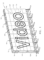
- FIG. 1 is a perspective view of an exemplary video display system according to the present disclosure.
- FIG. 2A is an exploded view of a video support structure according to the present disclosure.
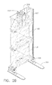
- FIG. 2B is an assembled view of a video support structure according to the present disclosure.
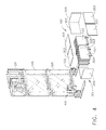
- FIG. 3 is a winch cart according to the present disclosure.
- FIG. 4 is a video support structure illustrating a method according to the present disclosure.
- FIG. 5 is a video support structure illustrating a method according to the present disclosure.
- FIG. 6A is a video support structure illustrating a method according to the present disclosure.
- FIG. 6B is an enlarged view of a portion of FIG. 6A .
- FIG. 7A is a video support structure illustrating a method according to the present disclosure.
- FIG. 7B is an enlarged view of a portion of FIG. 7A .
- FIG. 8A is a video support structure illustrating a method according to the present disclosure.
- FIG. 8B is an enlarged view of a portion of FIG. 8A .
- FIG. 9 is a video support structure illustrating a method according to the present disclosure.
- FIG. 10 is a video support structure illustrating a method according to the present disclosure.
- FIG. 11 is a video support structure illustrating a method according to the present disclosure.
- FIG. 12 is a video support structure illustrating a method according to the present disclosure.
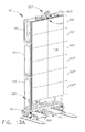
- FIG. 13A is a video support structure illustrating a method according to the present disclosure.
- FIG. 13B is an enlarged view of a portion of FIG. 13A .
- FIG. 14A is a video support structure illustrating a method according to the present disclosure.
- FIG. 14B is an enlarged view of a portion of FIG. 14A .
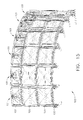
- FIG. 15 is an arrangement of video support structures forming a support system for a video display system having an arced geometry according to the present disclosure.
- FIG. 16 is an arrangement of video support structures forming a support system for a video display system having a non-symmetrical geometry according to the present disclosure.
- FIG. 17 illustrates a method for servicing a video display system with a video support structure according to the present disclosure.
- FIG. 18 is an enlarged view of a portion of the video display system of FIG. 17 .
- FIGS. 19A and 19B are enlarged views of the lifting device and the retention device of the video display system of FIG. 17 .
- FIG. 20 illustrates a method for servicing a video display system with a video support structure according to the present disclosure.
- FIG. 21 illustrates a method for servicing a video display system with a video support structure according to the present disclosure.
- FIG. 22 illustrates a method for servicing a video display system with a video support structure according to the present disclosure.
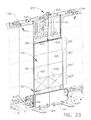
- FIG. 23 illustrates a method for servicing a video display system with a video support structure according to the present disclosure.
- FIG. 24 illustrates a method for servicing a video display system with a video support structure according to the present disclosure.
- FIG. 25 illustrates a method for servicing a video display system with a video support structure according to the present disclosure.
- FIG. 26 illustrates a method for servicing a video display system with a video support structure according to the present disclosure.
- FIG. 27 illustrates a method for servicing a video display system with a video support structure according to the present disclosure.
- Embodiments of the present disclosure permit the construction of a portable video support structure that is easily assembled and disassembled by hand, with little assistance of tools, by personnel having little or no technical skill, and further disassembled into relatively small units for transport and storage.
- Embodiments of the present disclosure create an illusion of a continuous image or video over a large surface.
- One embodiment includes a video display system having a plurality of high resolution and low resolution video display units, where one or more video display units are removed, serviced or replaced without disassembly of the video support structure.
- FIG. 1 shows a portable video display system 100 , according to an embodiment of the disclosure.
- the video display system 100 is made up of a plurality of video support structures 101 supporting a plurality of video display subcomponents 103 .
- the video support structures 101 are made up of base support assemblies 105 and a lift support assembly 107 that support and retain the plurality of video display subcomponents 103 .
- the video display subcomponents 103 are detachably engaged to one another via any latch or other suitable fastener known in the art for detachably engaging mechanical components.
- the latches do not require the assistance of tools to attach or detach the components from one another. Suitable latches may include draw latches.
- Portable video display system 100 of the present disclosure is portable, allowing easy assembly and disassembly, preferably with little or no assistance from tools.
- video display subcomponents 103 are made up of or contain one or more light emitting devices.
- Suitable light emitting devices include light emitting diodes (LEDs), for example, or any suitable light emitting elements such as video strips, organic light emitting diodes (OLEDs), fiber-optic lights, fluorescent lights, incandescent lights, neon lights, polymer light emitting diodes, electroluminescent lights, or combinations thereof.
- the light emitting devices may be a system of light emitting diodes (LEDs) housed within a housing that may be transparent, translucent, semi-transparent, semi-translucent, or a combination thereof.
- the LEDs may be configured to emit colored light based upon a signal from a controller.
- the light emitting devices may emit multiple colors of light simultaneously or at different times.
- multiple LEDs may be housed within the same housing. LEDs are configured to emit multiple colors such that the different colors are mixed within the housing thereby permitting additional control of the image or series of images displayed.
- the video display subcomponents 103 may be connected to each other in a grid pattern of wires.
- Wires may be connected to the light emitting devices by any suitable technique or connector. Wires can provide support for adjacent light emitting devices within the display device.
- the light emitting devices may be connected with wires that are fiber-optic cables permitting the light to be emitted from various sources.
- wires may be translucent, transparent, semi-transparent, semi-translucent, semi-opaque, opaque, or combinations thereof.
- the video display subcomponents 103 may utilize wireless control and/or wireless power to provide control and power from a remote location.
- the video display subcomponent 103 is a low resolution or a high resolution video panel configured to display lighting and/or video presentations. For example, a large number of closely spaced LEDs may be included thereby creating the effect that LEDs are of high resolution.
- the panels additionally or alternatively include OLEDs or other light sources capable of displaying images, video, or other visual displays.
- the video display subcomponents 103 may be transparent, translucent, semi-transparent, semi-translucent, opaque, semi-opaque, or combinations thereof.
- LEDs may be connected by electrical and/or control wires of other connectors with or without additional structural support.
- LED panels may permit high resolution including a large number of colored, closely spaced pixels permitting a clear, high resolution image, series of images, and/or video.
- the video display system 100 is configured, such that, the video display subcomponent 103 abuts directly to the adjacent video display subcomponent 103 , thus displaying an image as a substantially continuous display surface 109 capable of displaying a continuous image 111 .
- substantially continuous display surface 109 and continuous image 111 it is meant that the surface and image have the appearance of being continuous when being observed by a viewer with few or no gaps being visible between the video display subcomponents 103 . Minor gaps, seams or other discontinuities between the video display subcomponents 103 may be present, provided the visual appearance by an observer is continuous.
- the continuous image 111 may be any suitable display, including video, images or lighting effects.
- “video” includes moving or still images displayed on an electronic media interface, such as the plurality of video display subcomponents 103 , and may be provided in any known format for providing moving or still images.
- FIG. 2A shows an exploded view of the video support structure 101 , including the base support assemblies 105 and the lift support assembly 107 .
- FIG. 2B shows the video support structure 101 of FIG. 2A in an assembled configuration.
- the base support assemblies 105 include a footer structure 201 that provides stability and rests upon the ground or desired surface to receive the video display system 100 .
- the base support assembly 105 includes tapered connectors 203 that are received by receiving member 205 in the lift support assembly 107 and the base support assemblies 105 to provide a multi-level structure. The number of levels are not limited to the number of levels shown in FIGS.
- the tapered connectors 203 include a frusto-conical geometry having a tapered surface that frictionally engages a corresponding tapered surface in the receiving member 205 in the adjacent base support assembly 105 or the lift support assembly 107 .
- the engaged tapered surfaces provide assistance in alignment and provide stability for the assembled video support structure 101 .
- the tapered connectors 203 and the receiving members 205 are positioned at the four corners of the structure, but any number of tapered connectors 203 at any suitable position may be used.
- the video support structure 101 is not limited to the use of tapered connectors 203 and receiving members 205 and may use any suitable connection system known in the art for providing stacked structural components.
- the base support assemblies 105 and lift support assembly 107 may include additional features, such as ladders, hatches, walkways, conduit, cable runs, or any other features useful for providing functionality and increased serviceability to the video display system 100 .
- a base support assembly 105 including footer structure 201 , is positioned on a surface, such as the floor, of a venue. Additional base support assemblies 105 are provided and directed onto the base support assembly 105 having the footer structure 201 . Engagement between tapered connectors 203 and receiving members 205 provides support and alignment of the base support assemblies 105 . Additional base support assemblies 105 are directed onto the positioned base support assemblies and a multi-level structure is formed. Once a desired height is achieved, a lift support assembly 107 is directed onto the base support assembly 105 .
- the assembled video support structure is shown in FIG. 2B .
- the lift support assembly 107 includes a lifting device 207 and a retention device 209 .
- the lifting device 207 includes a series of sheaves, pulleys or other structures for receiving and guiding a cable, rope, wire, chain or other flexible member suitable for lifting (see expanded view in FIG. 7B ).
- the lifting device 207 is retractable between a first deployed position (see FIG. 2A ) and a second retracted position (see FIG. 2B ).
- the lifting device 207 is movable in a lateral direction along axis 211 .
- the lateral movement of lifting device 207 may be provided by any suitable method, including sliding or rolling of the lifting device 207 along a cylinder or bearing structure (see also FIGS.
- the retention device 209 includes clips, fasteners, features or other components for engaging and supporting a plurality of video display subcomponents 103 .
- the retention device 209 is movable along axis 211 and is movable by any suitable method, including sliding or rolling of the retention device 209 along a cylinder or bearing structure. While FIGS. 2A and 2B show a video support, a lift support assembly 107 wherein both the lifting device 207 and the retention device 209 are movable in a lateral direction of axis 211 , alternatively, one of the lifting device 207 or the retention device 209 may be fixed in the direction of axis 211 .
- the various components of the video support structure 101 are constructed of any suitable durable material.
- the components may be fabricated from metal, such as steel, galvanized steel, stainless steel, aluminum, their alloys or combinations therefore.
- a lightweight material such as aluminum or low gauge steel, is provided to provide a lighter weight component for handling, transportation and storage.
- support component surfaces are plated, painted, anodized, power coated or otherwise treated to resist corrosion, afford protection against the rigors of construction, storage and transportation, and to provide aesthetic appeal, for example, a flat or low gloss coating to conceal the video support structure 101 during the concert, performance, or stage production.
- the assembled video support structure 101 may include the base support assemblies 105 and lift support assemblies latched or detachably engaged with one another.
- the latching or detachable engagement may be provided by any suitable method, including hand actuated latches.
- Suitable latches include an adjustable latch or draw latch fastening device having a U-shaped yoke or hook, with a bracket and yoke interconnected to a handle that pivots from a hinge on a mounting bracket.
- coffin locks or similar flat surface connectors may be utilized to attach the base support assemblies 105 and the lift support assemblies 107 together.
- the latches are not limited to the above and may include any suitable fasteners for assembling/disassembling support structures. Preferably the latches allow engagement and disengagement without the assistance of tools.
- a winch dolly 401 is provided to provide lifting.
- the winch dolly includes a motorized winch 403 or similar device configured to retract or deploy a flexible lift member 701 , such as a cable, rope, wire, or chain about a wheel or drum (see for example, FIGS. 7A and 7B ).
- the flexible lift member 701 is directed over the lifting device 207 to lift the video display subcomponents 103 .
- the winch dolly 401 includes a storage hook 405 to support equipment, such as caster assembly 305 from transportation carts 301 (see example FIG. 4 ).
- FIGS. 4-14B illustrate the process of assembling the video display system 100 using a video support structure 101 .
- FIG. 4 also shows positioning of video display subcomponents 103 for assembly into the video display system 100 (see for example, FIG. 1 ).
- the video display subcomponents 103 are provided on transportation carts 301 shown with protective panels 303 partially removed. During transportation and/or storage protective panels 303 are secured around video display subcomponents 103 using any suitable latching or securing technique.
- the transportation carts 301 include caster assemblies 305 or other movement facilitating structures to permit positioning of the video display subcomponents 103 .
- the protective panels 303 protect the video display subcomponents 103 during transportation and storage and are removed prior to assembly of the video display system.
- the protective panels 303 are latched or fastened together and are preferably disengaged and removable without the assistance of tools.
- the plurality of video display subcomponents 103 are exposed in preparation for lifting and engaging.
- video display subcomponents 103 on caster assemblies 305 are conveyed and positioned in close proximity to the video support structure 101 .
- the video display subcomponents 103 are directed toward each other in direction 501 and latched together using latches or other suitable fasteners known in the art for detachably engaging mechanical components.
- the latches do not require the assistance of tools to attach or detach the components from one another.
- Suitable latches may include draw latches.
- FIG. 6A a first display tier 601 made up of engaged video display subcomponents 103 are detachably engaged to a hang bracket 603 .
- FIG. 6B shows an expanded view of area 602 of FIG. 6A .
- the detachable engagement between the hang bracket 603 and the video display subcomponents 103 can be accomplished with clips 605 or other suitable fastening devices.
- FIG. 7A a winch dolly 401 is positioned in close proximity to the video support structure 101 and a flexible lift member 701 is directed over the lifting device 207 .
- FIG. 7B shows an expanded view of area 702 of FIG. 7A .
- lifting device 207 includes at least one sheave 703 or pulley to support and guide the flexible lift member 701 . Any arrangement of sheaves 703 on the lifting device 207 that provides support and guidance of the flexible lift member 701 may be utilized. Also, as visible in FIG.
- the lifting device 207 and retention device 209 are mounted on positioning cylinders 705 that support the lifting device 207 and retention device 209 and also permit lateral motion of the lifting device 207 and retention device with respect to the lift support assembly 107 .
- the movement is permitted by rolling of other suitable bearing arrangements that allow lateral movement of the lifting device 207 and the retention device 209 , while the lift support assembly 107 remains fixed (see also FIG. 2A ).
- FIG. 8A shows an expanded view of area 802 of FIG. 8A .
- a lift bracket 801 attached to the flexible lift member 701 is detachably engaged to the hang bracket 603 .
- the lift bracket 801 and hang bracket 603 are detachably engaged using suitable fasteners.
- the lift bracket 801 and the hang bracket 603 are engaged using one or more lift locking pins 803 (as shown in FIG. 8B ), latches or similar fasteners that can be disengaged without the assistance of tools.
- Suitable locking pins include, for example, but are not limited to, adjustable expanding pins, positive locking quick-release pins, double-ball self-locking pins, clevis pins having one or more holes to receive a cotter pin or hairpin, clevis pins having a machined grove to receive a snap ring, swivel-clip locking clevis pins, hitch pins, linch pins, or lock pins.
- the first display tier 601 is lifted using the winch dolly 401 and flexible lift member 701 .
- the first display tier 601 is lifted above a second display tier 601 ′ and the caster assemblies 305 are directed toward the video support structure 101 in direction 901 such that the first display tier 601 aligns vertically with second display tier 601 ′ (as shown in FIG. 10 ).
- FIG. 10 shows the caster assemblies 305 with video display subcomponents 103 in first display tier 601 in vertical alignment with video display subcomponents 103 in second display tier 601 ′.
- the alignment of the first display tier 601 and the second display tier 601 ′ is such that the first display tier 601 can be lowered directly onto the second display tier 601 ′.
- the first display tier 601 is lowered onto second display tier 601 ′ and the first display tier 601 and the second display tier 601 ′ are latched together using latches or other suitable fasteners known in the art for detachably engaging mechanical components.
- the latches do not require the assistance of tools to attach or detach the components from one another. Suitable latches may include draw latches.
- the video display subcomponents 103 automatically latch together when the first display tier 601 contacts the second display tier 601 ′ wherein the weight of the first display tier 601 actuates the latches.
- the first tier 601 and the second tier 601 ′ are lifted together with the winch dolly 401 and the flexible lift member 701 .
- a third display tier 601 ′′ is positioned in alignment with the second display tier 601 ′ and the process is repeated until a desired height is achieved (see FIG. 13A ).
- FIG. 13A shows an expanded view of area 1302 of FIG. 13A .
- the hang bracket is engaged with retention device with a retention locking pin 1301 .
- Latches or similar fasteners may also be used that, in one embodiment, can be disengaged without the assistance of tools.
- the built-up continuous display surface 109 made up of display tiers 601 , 601 ′, 601 ′′, 601 ′′′, 601 ′′′′, and 601 is not limited to the number of tiers or the specific configuration of video display subcomponents 103 shown in FIG. 13A . Any number of display tiers 601 and any suitable configuration of video display subcomponents 103 may be utilized.
- FIG. 14A includes an additional method step wherein the lifting device 207 is retracted to a position within the lift support assembly to minimize its visibility during operation of the video display system 100 (see for example, FIG. 1 ).
- FIG. 14B shows an expanded view of area 1402 of FIG. 14A .
- FIG. 14B shows detail of the lifting device 207 in the retracted position.
- additional video support structures 101 may be positioned next to each other and the process of FIGS. 4-14B is repeated until the desired lateral size of the system is provided.
- FIG. 15 An alternate embodiment of the video display system 100 is shown in FIG. 15 with the video display subcomponents 103 removed, wherein the video support structures 101 are assembled in an arc-like geometry to form a curved continuous display surface. Still another alternate embodiment of the video display system 100 is shown in FIG. 16 , wherein a discontinuous structure is shown to allow bridging over doorways or other features.
- the video display system 100 of the present disclosure permits serviceability without disassembly of the entire or significant portions of the video display system 100 .
- section 1700 and repair section 1701 are detached from each other, by disengaging the latches or other fasteners holding the video display subcomponents 103 together in the lateral direction.
- the display surface 109 is separated by moving sections 1700 of video display subcomponents 103 in directions 1705 to isolate a repair section 1701 including one or more video display subcomponents 103 ′ requiring replacement or repair.
- the retention devices 209 in section 1700 are moved in direction 1703 to permit movement of the video display subcomponents 103 with respect to the video support structure 101 .
- This movement is shown in greater detail in the expanded view 1707 , shown in FIG. 18 , wherein the movement in direction 1703 is of the retention device, the hang bracket 603 and the video display subcomponents 103 with respect to a fixed lift support assembly 107 .
- FIGS. 19A and 19B show the retention device 209 and the lifting device 207 with the hang bracket 603 and the video display subcomponents 103 removed.
- the retention device 209 and lifting device 207 are mounted on positioning cylinders 705 that are fixedly mounted in the lift support assembly 107 that permit lateral motion within the lift support assembly 107 .
- the motion is permitted by use of bearings or other similar structures that reduce friction and allow relative motion between retention device 209 /lifting device 207 and the positioning cylinders.
- the movement along the positioning cylinders 705 allows the screen to be separated at any desirable location along the display surface 109 .
- the display surface can be separated into section 1700 and repair section 1701 by moving of each of the retention members in their respective lift support assemblies 107 .
- the lifting device 207 may be deployed to assist in the disassembly of the repair section 1700 .
- the repair section 1700 is lowered to caster assemblies 305 and the display tiers 601 are separated from one another.
- the remaining display tiers 601 are lifted from the tier stowed on caster assembly 305 .
- the caster assembly 305 is moved in direction 2201 to align the caster assembly 305 with the next display tier 601 and the process is repeated (see FIGS. 23-24 ) until video display subcomponents 103 ′ requiring replacement or repair are disengaged from the isolated section 1701 (see FIGS. 24-25 ).
- the video display subcomponents 103 ′ requiring replacement or repair can be removed and replacement video display subcomponents 103 ” may be positioned as a replacement.
- the video display subcomponents 103 ′ requiring replacement or repair may be removed and serviced and returned to service once servicing is complete.
- the process of FIGS. 17-24 are reversed.
- the video display subcomponents 103 ′′ are latched or fastened to the adjacent video display subcomponents 103 .
- the sections 1700 are moved in direction 1905 , with the retention device 209 moving in direction 1903 to form continuous display surface 109 .
- the video display subcomponents 103 are all latched or fastened together and the display system 100 is in a suitable condition to return to service.
Landscapes
- Engineering & Computer Science (AREA)
- Physics & Mathematics (AREA)
- General Physics & Mathematics (AREA)
- Theoretical Computer Science (AREA)
- General Engineering & Computer Science (AREA)
- Microelectronics & Electronic Packaging (AREA)
- Optics & Photonics (AREA)
- Mechanical Engineering (AREA)
- Devices For Indicating Variable Information By Combining Individual Elements (AREA)
Abstract
A video display system having a plurality of portable video support structures. Each of the portable video support structures includes at least one base support assembly and at least one lift support assembly having a lifting device configured to lift a plurality of video display subcomponents and a retention device receiving and supporting the plurality of video display subcomponents. One or both of the lifting device and the retention device is capable of movement to position the plurality of video display subcomponents and the video display subcomponents detachably engaged with one another to form a substantially continuous display surface. A method of assembling a video display system and a video support structure are also disclosed.
Description
- The present invention is directed to a video support structure and a video support system. More specifically, the present invention is directed to a support structure having lifting and support members capable of positioning and servicing individual video display subcomponents.
- In the performance industry, video display systems operate in conjunction with other multi-media systems, for example, lighting and sound, as part of a concert, performance, or stage production. Support structures for the video display systems typically include complicated and/or large individual components that require assembly of the components. Use of conventional connectors, such as threaded bolts or screws, increases the complexity of assembly and further increases the time and labor required for assembly and disassembly. When being part of a touring production, the video support structures must be sturdy to withstand the rigors of outdoor use, yet portable and capable of being broken down into relatively smaller units that can be loaded into trucks or other vehicles for transport. In addition, the portable structures must be capable of assembly and disassembly, by personnel having little or no technical skill. The above benefits must be accounted for while providing a video support structure and a video display system in conjunction with multi-media productions.
- Video support structures as part of a concert, performance, or stage production are typically of custom design requiring on-site fabrication and alterations, often resulting in the added expense of additional time and labor to complete the construction. Structural components that permit the option of alterations, for example, a curved backdrop or a bridge, while maintaining ease of assembly and disassembly, would be desirable.
- Video display systems also include a plurality of illumination panels or video display units, including low resolution illumination panels, high resolution illumination panels, or a combination thereof. Illumination panels are part of a video display system and interconnected so that individual illumination panels project an image as a portion of a larger video display. When a defective video display unit is observed, it detracts from the multi-media presentation, and therefore, must be replaced. Removing and replacing one or more video display units within the video support structure is a difficult task due to the complexity of the video support structure. Typically, in the current system, entire sections or the entire displays must be fully disassembled to remove or service an individual video display unit. This extensive disassembly increases the cost and time associated with servicing and maintaining display systems.
- What is needed is a portable video support structure and a video display system incorporating low and/or high resolution video display units, capable of custom installation, easily assembled and disassembled with little or no technical skill, disassembled into smaller components for transportation and storage, having replaceable video display units, where the structure does not suffer from the drawbacks of the prior art.
- One aspect of the disclosure refers to a portable video support structure having at least one base support assembly and at least one lift support assembly. The lift support assembly includes a lifting device configured to lift a plurality of video display subcomponents and a retention device configured to receive and support the plurality of video display subcomponents. One or both of the lifting device and the retention device are capable of movement to position the plurality of video display subcomponents.
- Another aspect of the disclosure refers to a method of assembling a video display system. The method includes providing a video support structure having at least one base support assembly and at least one lift support assembly. The lift support assembly includes a lifting device and a retention device. A video display subcomponent is provided and the video display subcomponent is lifted with the lifting device. An additional video display subcomponent is provided and detachably engaged with the video display subcomponent. The video display subcomponent and the additional video display subcomponent are lifted with the lifting device. Additional video display subcomponents are provided, detachably engaged and lifted until a predetermined number of video display subcomponents are engaged with one another. One of the video display subcomponents or the additional video display subcomponents are detachably engaged to the retention member to form a substantially continuous display surface.
- Still another aspect of the disclosure refers to a video display system having a plurality of portable video support structures. Each of the portable video support structures include at least one base support assembly and at least one lift support assembly having a lifting device configured to lift a plurality of video display subcomponents and a retention device receiving and supporting the plurality of video display subcomponents. One or both of the lifting device and the retention device is capable of movement to position the plurality of video display subcomponents and the video display subcomponents detachably engaged with one another to form a substantially continuous display surface.
- Other features and advantages of the present invention will be apparent from the following more detailed description of the preferred embodiment, taken in conjunction with the accompanying drawings which illustrate, by way of example, the principles of the invention.
-
FIG. 1 is a perspective view of an exemplary video display system according to the present disclosure. -
FIG. 2A is an exploded view of a video support structure according to the present disclosure. -
FIG. 2B is an assembled view of a video support structure according to the present disclosure. -
FIG. 3 is a winch cart according to the present disclosure. -
FIG. 4 is a video support structure illustrating a method according to the present disclosure. -
FIG. 5 is a video support structure illustrating a method according to the present disclosure. -
FIG. 6A is a video support structure illustrating a method according to the present disclosure. -
FIG. 6B is an enlarged view of a portion ofFIG. 6A . -
FIG. 7A is a video support structure illustrating a method according to the present disclosure. -
FIG. 7B is an enlarged view of a portion ofFIG. 7A . -
FIG. 8A is a video support structure illustrating a method according to the present disclosure. -
FIG. 8B is an enlarged view of a portion ofFIG. 8A . -
FIG. 9 is a video support structure illustrating a method according to the present disclosure. -
FIG. 10 is a video support structure illustrating a method according to the present disclosure. -
FIG. 11 is a video support structure illustrating a method according to the present disclosure. -
FIG. 12 is a video support structure illustrating a method according to the present disclosure. -
FIG. 13A is a video support structure illustrating a method according to the present disclosure. -
FIG. 13B is an enlarged view of a portion ofFIG. 13A . -
FIG. 14A is a video support structure illustrating a method according to the present disclosure. -
FIG. 14B is an enlarged view of a portion ofFIG. 14A . -
FIG. 15 is an arrangement of video support structures forming a support system for a video display system having an arced geometry according to the present disclosure. -
FIG. 16 is an arrangement of video support structures forming a support system for a video display system having a non-symmetrical geometry according to the present disclosure. -
FIG. 17 illustrates a method for servicing a video display system with a video support structure according to the present disclosure. -
FIG. 18 is an enlarged view of a portion of the video display system ofFIG. 17 . -
FIGS. 19A and 19B are enlarged views of the lifting device and the retention device of the video display system ofFIG. 17 . -
FIG. 20 illustrates a method for servicing a video display system with a video support structure according to the present disclosure. -
FIG. 21 illustrates a method for servicing a video display system with a video support structure according to the present disclosure. -
FIG. 22 illustrates a method for servicing a video display system with a video support structure according to the present disclosure. -
FIG. 23 illustrates a method for servicing a video display system with a video support structure according to the present disclosure. -
FIG. 24 illustrates a method for servicing a video display system with a video support structure according to the present disclosure. -
FIG. 25 illustrates a method for servicing a video display system with a video support structure according to the present disclosure. -
FIG. 26 illustrates a method for servicing a video display system with a video support structure according to the present disclosure. -
FIG. 27 illustrates a method for servicing a video display system with a video support structure according to the present disclosure. - Wherever possible, the same reference numbers will be used throughout the drawings to represent the same parts.
- Provided is an exemplary portable video support structure and a video display system. Embodiments of the present disclosure permit the construction of a portable video support structure that is easily assembled and disassembled by hand, with little assistance of tools, by personnel having little or no technical skill, and further disassembled into relatively small units for transport and storage. Embodiments of the present disclosure create an illusion of a continuous image or video over a large surface.
- One embodiment includes a video display system having a plurality of high resolution and low resolution video display units, where one or more video display units are removed, serviced or replaced without disassembly of the video support structure.
-
FIG. 1 shows a portablevideo display system 100, according to an embodiment of the disclosure. Thevideo display system 100 is made up of a plurality ofvideo support structures 101 supporting a plurality ofvideo display subcomponents 103. Thevideo support structures 101 are made up ofbase support assemblies 105 and alift support assembly 107 that support and retain the plurality ofvideo display subcomponents 103. Thevideo display subcomponents 103 are detachably engaged to one another via any latch or other suitable fastener known in the art for detachably engaging mechanical components. Preferably, the latches do not require the assistance of tools to attach or detach the components from one another. Suitable latches may include draw latches. Portablevideo display system 100 of the present disclosure is portable, allowing easy assembly and disassembly, preferably with little or no assistance from tools. - In one embodiment,
video display subcomponents 103 are made up of or contain one or more light emitting devices. Suitable light emitting devices include light emitting diodes (LEDs), for example, or any suitable light emitting elements such as video strips, organic light emitting diodes (OLEDs), fiber-optic lights, fluorescent lights, incandescent lights, neon lights, polymer light emitting diodes, electroluminescent lights, or combinations thereof. For example, the light emitting devices may be a system of light emitting diodes (LEDs) housed within a housing that may be transparent, translucent, semi-transparent, semi-translucent, or a combination thereof. In one embodiment, the LEDs may be configured to emit colored light based upon a signal from a controller. In another embodiment, the light emitting devices may emit multiple colors of light simultaneously or at different times. In yet another embodiment, multiple LEDs may be housed within the same housing. LEDs are configured to emit multiple colors such that the different colors are mixed within the housing thereby permitting additional control of the image or series of images displayed. - In another embodiment, the
video display subcomponents 103 may be connected to each other in a grid pattern of wires. Wires may be connected to the light emitting devices by any suitable technique or connector. Wires can provide support for adjacent light emitting devices within the display device. In another embodiment, the light emitting devices may be connected with wires that are fiber-optic cables permitting the light to be emitted from various sources. In yet another embodiment, wires may be translucent, transparent, semi-transparent, semi-translucent, semi-opaque, opaque, or combinations thereof. In another embodiment, thevideo display subcomponents 103 may utilize wireless control and/or wireless power to provide control and power from a remote location. - In yet another embodiment, the
video display subcomponent 103 is a low resolution or a high resolution video panel configured to display lighting and/or video presentations. For example, a large number of closely spaced LEDs may be included thereby creating the effect that LEDs are of high resolution. In another embodiment, the panels additionally or alternatively include OLEDs or other light sources capable of displaying images, video, or other visual displays. Thevideo display subcomponents 103 may be transparent, translucent, semi-transparent, semi-translucent, opaque, semi-opaque, or combinations thereof. In addition, LEDs may be connected by electrical and/or control wires of other connectors with or without additional structural support. In one embodiment, LED panels may permit high resolution including a large number of colored, closely spaced pixels permitting a clear, high resolution image, series of images, and/or video. - The
video display system 100 is configured, such that, thevideo display subcomponent 103 abuts directly to the adjacentvideo display subcomponent 103, thus displaying an image as a substantiallycontinuous display surface 109 capable of displaying acontinuous image 111. By substantiallycontinuous display surface 109 andcontinuous image 111, it is meant that the surface and image have the appearance of being continuous when being observed by a viewer with few or no gaps being visible between thevideo display subcomponents 103. Minor gaps, seams or other discontinuities between thevideo display subcomponents 103 may be present, provided the visual appearance by an observer is continuous. Thecontinuous image 111 may be any suitable display, including video, images or lighting effects. As utilized herein, “video” includes moving or still images displayed on an electronic media interface, such as the plurality ofvideo display subcomponents 103, and may be provided in any known format for providing moving or still images. -
FIG. 2A shows an exploded view of thevideo support structure 101, including thebase support assemblies 105 and thelift support assembly 107.FIG. 2B shows thevideo support structure 101 ofFIG. 2A in an assembled configuration. As illustrated inFIGS. 2A and 2B , thebase support assemblies 105 include afooter structure 201 that provides stability and rests upon the ground or desired surface to receive thevideo display system 100. As is visible inFIG. 2A , thebase support assembly 105 includes taperedconnectors 203 that are received by receivingmember 205 in thelift support assembly 107 and thebase support assemblies 105 to provide a multi-level structure. The number of levels are not limited to the number of levels shown inFIGS. 2A and 2B , but may include any number of levels desired to provide the height and portability of the desiredvideo display system 100. The taperedconnectors 203 include a frusto-conical geometry having a tapered surface that frictionally engages a corresponding tapered surface in the receivingmember 205 in the adjacentbase support assembly 105 or thelift support assembly 107. The engaged tapered surfaces provide assistance in alignment and provide stability for the assembledvideo support structure 101. As shown inFIG. 2A , the taperedconnectors 203 and the receivingmembers 205 are positioned at the four corners of the structure, but any number of taperedconnectors 203 at any suitable position may be used. Thevideo support structure 101 is not limited to the use of taperedconnectors 203 and receivingmembers 205 and may use any suitable connection system known in the art for providing stacked structural components. Thebase support assemblies 105 and liftsupport assembly 107 may include additional features, such as ladders, hatches, walkways, conduit, cable runs, or any other features useful for providing functionality and increased serviceability to thevideo display system 100. - To assemble the
video support structure 101, abase support assembly 105, includingfooter structure 201, is positioned on a surface, such as the floor, of a venue. Additionalbase support assemblies 105 are provided and directed onto thebase support assembly 105 having thefooter structure 201. Engagement betweentapered connectors 203 and receivingmembers 205 provides support and alignment of thebase support assemblies 105. Additionalbase support assemblies 105 are directed onto the positioned base support assemblies and a multi-level structure is formed. Once a desired height is achieved, alift support assembly 107 is directed onto thebase support assembly 105. The assembled video support structure is shown inFIG. 2B . - As shown in
FIGS. 2A and 2B , thelift support assembly 107 includes alifting device 207 and aretention device 209. Thelifting device 207 includes a series of sheaves, pulleys or other structures for receiving and guiding a cable, rope, wire, chain or other flexible member suitable for lifting (see expanded view inFIG. 7B ). Thelifting device 207 is retractable between a first deployed position (seeFIG. 2A ) and a second retracted position (seeFIG. 2B ). In addition, thelifting device 207 is movable in a lateral direction alongaxis 211. The lateral movement of liftingdevice 207 may be provided by any suitable method, including sliding or rolling of thelifting device 207 along a cylinder or bearing structure (see alsoFIGS. 19A and 19B ). Theretention device 209 includes clips, fasteners, features or other components for engaging and supporting a plurality ofvideo display subcomponents 103. Like thelifting device 207, theretention device 209 is movable alongaxis 211 and is movable by any suitable method, including sliding or rolling of theretention device 209 along a cylinder or bearing structure. WhileFIGS. 2A and 2B show a video support, alift support assembly 107 wherein both thelifting device 207 and theretention device 209 are movable in a lateral direction ofaxis 211, alternatively, one of thelifting device 207 or theretention device 209 may be fixed in the direction ofaxis 211. - The various components of the
video support structure 101 are constructed of any suitable durable material. For example, the components may be fabricated from metal, such as steel, galvanized steel, stainless steel, aluminum, their alloys or combinations therefore. In one embodiment, a lightweight material, such as aluminum or low gauge steel, is provided to provide a lighter weight component for handling, transportation and storage. In another embodiment, support component surfaces are plated, painted, anodized, power coated or otherwise treated to resist corrosion, afford protection against the rigors of construction, storage and transportation, and to provide aesthetic appeal, for example, a flat or low gloss coating to conceal thevideo support structure 101 during the concert, performance, or stage production. - As shown in
FIG. 2B , the assembledvideo support structure 101 may include thebase support assemblies 105 and lift support assemblies latched or detachably engaged with one another. The latching or detachable engagement may be provided by any suitable method, including hand actuated latches. Suitable latches include an adjustable latch or draw latch fastening device having a U-shaped yoke or hook, with a bracket and yoke interconnected to a handle that pivots from a hinge on a mounting bracket. Alternatively, coffin locks or similar flat surface connectors may be utilized to attach thebase support assemblies 105 and thelift support assemblies 107 together. The latches are not limited to the above and may include any suitable fasteners for assembling/disassembling support structures. Preferably the latches allow engagement and disengagement without the assistance of tools. - As shown in
FIG. 3 , awinch dolly 401 is provided to provide lifting. The winch dolly includes amotorized winch 403 or similar device configured to retract or deploy aflexible lift member 701, such as a cable, rope, wire, or chain about a wheel or drum (see for example,FIGS. 7A and 7B ). Theflexible lift member 701 is directed over thelifting device 207 to lift thevideo display subcomponents 103. In one embodiment, as shown inFIG. 4 , thewinch dolly 401 includes astorage hook 405 to support equipment, such ascaster assembly 305 from transportation carts 301 (see exampleFIG. 4 ). -
FIGS. 4-14B illustrate the process of assembling thevideo display system 100 using avideo support structure 101. -
FIG. 4 also shows positioning ofvideo display subcomponents 103 for assembly into the video display system 100 (see for example,FIG. 1 ). Thevideo display subcomponents 103 are provided ontransportation carts 301 shown withprotective panels 303 partially removed. During transportation and/or storageprotective panels 303 are secured aroundvideo display subcomponents 103 using any suitable latching or securing technique. Thetransportation carts 301 includecaster assemblies 305 or other movement facilitating structures to permit positioning of thevideo display subcomponents 103. Theprotective panels 303 protect thevideo display subcomponents 103 during transportation and storage and are removed prior to assembly of the video display system. Theprotective panels 303 are latched or fastened together and are preferably disengaged and removable without the assistance of tools. The plurality ofvideo display subcomponents 103 are exposed in preparation for lifting and engaging. - Referring to
FIG. 5 ,video display subcomponents 103 oncaster assemblies 305 are conveyed and positioned in close proximity to thevideo support structure 101. Thevideo display subcomponents 103 are directed toward each other indirection 501 and latched together using latches or other suitable fasteners known in the art for detachably engaging mechanical components. Preferably, the latches do not require the assistance of tools to attach or detach the components from one another. Suitable latches may include draw latches. - As shown in
FIG. 6A , afirst display tier 601 made up of engagedvideo display subcomponents 103 are detachably engaged to ahang bracket 603.FIG. 6B shows an expanded view ofarea 602 ofFIG. 6A . The detachable engagement between thehang bracket 603 and thevideo display subcomponents 103 can be accomplished withclips 605 or other suitable fastening devices. - As shown in
FIG. 7A , awinch dolly 401 is positioned in close proximity to thevideo support structure 101 and aflexible lift member 701 is directed over thelifting device 207.FIG. 7B shows an expanded view ofarea 702 ofFIG. 7A . As is visible inFIG. 7B , liftingdevice 207 includes at least onesheave 703 or pulley to support and guide theflexible lift member 701. Any arrangement ofsheaves 703 on thelifting device 207 that provides support and guidance of theflexible lift member 701 may be utilized. Also, as visible inFIG. 7B , thelifting device 207 andretention device 209 are mounted on positioningcylinders 705 that support thelifting device 207 andretention device 209 and also permit lateral motion of thelifting device 207 and retention device with respect to thelift support assembly 107. The movement is permitted by rolling of other suitable bearing arrangements that allow lateral movement of thelifting device 207 and theretention device 209, while thelift support assembly 107 remains fixed (see alsoFIG. 2A ). - As shown in
FIG. 8A , theflexible lift member 701 is attached to thehang bracket 603 to facilitate lifting with thewinch dolly 401.FIG. 8B shows an expanded view ofarea 802 ofFIG. 8A . As is visible inFIG. 8B , alift bracket 801 attached to theflexible lift member 701 is detachably engaged to thehang bracket 603. Thelift bracket 801 and hangbracket 603 are detachably engaged using suitable fasteners. In one embodiment, thelift bracket 801 and thehang bracket 603 are engaged using one or more lift locking pins 803 (as shown inFIG. 8B ), latches or similar fasteners that can be disengaged without the assistance of tools. Suitable locking pins include, for example, but are not limited to, adjustable expanding pins, positive locking quick-release pins, double-ball self-locking pins, clevis pins having one or more holes to receive a cotter pin or hairpin, clevis pins having a machined grove to receive a snap ring, swivel-clip locking clevis pins, hitch pins, linch pins, or lock pins. - As shown in
FIG. 9 , thefirst display tier 601 is lifted using thewinch dolly 401 andflexible lift member 701. Thefirst display tier 601 is lifted above asecond display tier 601′ and thecaster assemblies 305 are directed toward thevideo support structure 101 indirection 901 such that thefirst display tier 601 aligns vertically withsecond display tier 601′ (as shown inFIG. 10 ). -
FIG. 10 shows thecaster assemblies 305 withvideo display subcomponents 103 infirst display tier 601 in vertical alignment withvideo display subcomponents 103 insecond display tier 601′. The alignment of thefirst display tier 601 and thesecond display tier 601′ is such that thefirst display tier 601 can be lowered directly onto thesecond display tier 601′. - As shown in
FIG. 11 , thefirst display tier 601 is lowered ontosecond display tier 601′ and thefirst display tier 601 and thesecond display tier 601′ are latched together using latches or other suitable fasteners known in the art for detachably engaging mechanical components. Preferably, the latches do not require the assistance of tools to attach or detach the components from one another. Suitable latches may include draw latches. In another embodiment, thevideo display subcomponents 103 automatically latch together when thefirst display tier 601 contacts thesecond display tier 601′ wherein the weight of thefirst display tier 601 actuates the latches. - As shown in
FIG. 12 , thefirst tier 601 and thesecond tier 601′ are lifted together with thewinch dolly 401 and theflexible lift member 701. Similar to the step shown inFIGS. 9 and 10, athird display tier 601″ is positioned in alignment with thesecond display tier 601′ and the process is repeated until a desired height is achieved (seeFIG. 13A ). - As is shown in
FIG. 13A , thelift bracket 801 is disengaged from thehang bracket 603 and thehang bracket 603 is engaged to theretention device 209.FIG. 13B shows an expanded view ofarea 1302 ofFIG. 13A . As is best visible inFIG. 13B , the hang bracket is engaged with retention device with aretention locking pin 1301. Latches or similar fasteners may also be used that, in one embodiment, can be disengaged without the assistance of tools. - The built-up
continuous display surface 109 made up ofdisplay tiers video display subcomponents 103 shown inFIG. 13A . Any number ofdisplay tiers 601 and any suitable configuration ofvideo display subcomponents 103 may be utilized.FIG. 14A includes an additional method step wherein thelifting device 207 is retracted to a position within the lift support assembly to minimize its visibility during operation of the video display system 100 (see for example,FIG. 1 ).FIG. 14B shows an expanded view ofarea 1402 ofFIG. 14A .FIG. 14B shows detail of thelifting device 207 in the retracted position. In addition, to continue expanding laterally the size of thevideo display system 100, additionalvideo support structures 101 may be positioned next to each other and the process ofFIGS. 4-14B is repeated until the desired lateral size of the system is provided. - An alternate embodiment of the
video display system 100 is shown inFIG. 15 with thevideo display subcomponents 103 removed, wherein thevideo support structures 101 are assembled in an arc-like geometry to form a curved continuous display surface. Still another alternate embodiment of thevideo display system 100 is shown inFIG. 16 , wherein a discontinuous structure is shown to allow bridging over doorways or other features. - As shown in
FIGS. 17-27 , thevideo display system 100 of the present disclosure permits serviceability without disassembly of the entire or significant portions of thevideo display system 100. To provide a repair or replacement of individual or groups ofvideo display subcomponents 103,section 1700 andrepair section 1701 are detached from each other, by disengaging the latches or other fasteners holding thevideo display subcomponents 103 together in the lateral direction. As shown inFIG. 17 , thedisplay surface 109 is separated by movingsections 1700 ofvideo display subcomponents 103 indirections 1705 to isolate arepair section 1701 including one or morevideo display subcomponents 103′ requiring replacement or repair. To provide the isolation, theretention devices 209 insection 1700 are moved indirection 1703 to permit movement of thevideo display subcomponents 103 with respect to thevideo support structure 101. This movement is shown in greater detail in the expandedview 1707, shown inFIG. 18 , wherein the movement indirection 1703 is of the retention device, thehang bracket 603 and thevideo display subcomponents 103 with respect to a fixedlift support assembly 107. -
FIGS. 19A and 19B show theretention device 209 and thelifting device 207 with thehang bracket 603 and thevideo display subcomponents 103 removed. As described above with respect toFIG. 7 , theretention device 209 and liftingdevice 207 are mounted on positioningcylinders 705 that are fixedly mounted in thelift support assembly 107 that permit lateral motion within thelift support assembly 107. The motion is permitted by use of bearings or other similar structures that reduce friction and allow relative motion betweenretention device 209/lifting device 207 and the positioning cylinders. When a plurality of video support structures are assembled together, the movement along the positioningcylinders 705 allows the screen to be separated at any desirable location along thedisplay surface 109. As described above inFIG. 17 , the display surface can be separated intosection 1700 andrepair section 1701 by moving of each of the retention members in their respectivelift support assemblies 107. - As shown in
FIG. 20 , in one embodiment, thelifting device 207 may be deployed to assist in the disassembly of therepair section 1700. As shown, therepair section 1700 is lowered tocaster assemblies 305 and thedisplay tiers 601 are separated from one another. As shown inFIG. 21 , the remainingdisplay tiers 601 are lifted from the tier stowed oncaster assembly 305. As shown inFIG. 22 , thecaster assembly 305 is moved in direction 2201 to align thecaster assembly 305 with thenext display tier 601 and the process is repeated (seeFIGS. 23-24 ) untilvideo display subcomponents 103′ requiring replacement or repair are disengaged from the isolated section 1701 (seeFIGS. 24-25 ). As shown inFIG. 25 , thevideo display subcomponents 103′ requiring replacement or repair can be removed and replacementvideo display subcomponents 103” may be positioned as a replacement. Alternatively, thevideo display subcomponents 103′ requiring replacement or repair may be removed and serviced and returned to service once servicing is complete. Once the replacementvideo display subcomponents 103″ are in position, the process ofFIGS. 17-24 are reversed. Thevideo display subcomponents 103″ are latched or fastened to the adjacentvideo display subcomponents 103. Thereafter, as shown inFIG. 27 , thesections 1700 are moved indirection 1905, with theretention device 209 moving indirection 1903 to formcontinuous display surface 109. Thevideo display subcomponents 103 are all latched or fastened together and thedisplay system 100 is in a suitable condition to return to service. - While the invention has been described with reference to a preferred embodiment, it will be understood by those skilled in the art that various changes may be made and equivalents may be substituted for elements thereof without departing from the scope of the invention. In addition, many modifications may be made to adapt a particular situation or material to the teachings of the invention without departing from the essential scope thereof. Therefore, it is intended that the invention not be limited to the particular embodiment disclosed as the best mode contemplated for carrying out this invention, but that the invention will include all embodiments falling within the scope of the appended claims.
Claims (20)
1. A portable video support structure comprising:
at least one base support assembly; and
at least one lift support assembly having:
a lifting device configured to lift a plurality of video display subcomponents; and
a retention device configured to receive and support the plurality of video display subcomponents;
wherein one or both of the lifting device and the retention device is capable of movement to position the plurality of video display subcomponents.
2. The portable video support structure of claim 1 , wherein the plurality of video display subcomponents include low resolution video panels, high resolution video panels or combinations thereof.
3. The portable video support structure of claim 1 , wherein the lifting device includes a flexible lift member and a winch.
4. The portable video support structure of claim 1 , wherein the at least one base support assembly includes tapered connectors.
5. The portable video support structure of claim 1 , wherein the lifting device is configurable into a retracted position and a deployed position.
6. A method of assembling a video display system comprising:
providing a video support structure having at least one base support assembly and at least one lift support assembly, the lift support assembly having a lifting device; and a retention device;
providing a video display subcomponent;
lifting the video display subcomponent with the lifting device;
providing an additional video display subcomponent;
detachably engaging the additional video display subcomponent with the video display subcomponent;
lifting the video display subcomponent and the additional video display subcomponent with the lifting device;
providing, lifting and detachably engaging additional video display subcomponents until a predetermined number of video display subcomponents are engaged with one another; and
detachably engaging one of the video display subcomponents or the additional video display subcomponents to the retention member to form a substantially continuous display surface.
7. The method of claim 6 , wherein the plurality of video display subcomponents include low resolution video panels, a high resolution video panel or combinations thereof.
8. The method of claim 6 , further comprising providing an additional video support structure.
9. The method of claim 6 , further comprising detaching a section of video display subcomponents.
10. The method of claim 9 , further comprising moving the retention device to separate the section of video display components.
11. The method of claim 10 , further comprising removing and replacing at least one video display subcomponent.
12. The method of claim 10 , further comprising moving the lifting device to separate the section of video display components.
13. The method of claim 12 , further comprising removing and replacing at least one video display subcomponent.
14. The method of claim 6 , further comprising directing the lifting device into a retracted position after detachably engaging the one of the video display subcomponents or the additional video display subcomponents to the retention member.
15. A video display system comprising:
a plurality of portable video support structures each comprising:
at least one base support assembly; and
at least one lift support assembly having:
a lifting device configured to lift a plurality of video display subcomponents; and
a retention device receiving and supporting the plurality of video display subcomponents;
wherein one or both of the lifting device and the retention device is capable of movement to position the plurality of video display subcomponents and the video display subcomponents being detachably engaged with one another to form a substantially continuous display surface.
16. The video display system of claim 15 , wherein the plurality of video display subcomponents include low resolution video panels, a high resolution video panel or combinations thereof.
17. The video display system of claim 15 , wherein the video display system includes greater than two video display subcomponents.
18. The video display system of claim 15 , wherein the retention device is movable to separate the section of video display components.
19. The video display system of claim 15 , wherein the lifting device is movable to separate the section of video display components.
20. The video display system of claim 15 , wherein the lifting device is configurable into a retracted position and a deployed position.
Applications Claiming Priority (2)
| Application Number | Priority Date | Filing Date | Title |
|---|---|---|---|
| BE201300129 | 2013-02-28 | ||
| BE2013/0129 | 2013-02-28 |
Publications (1)
| Publication Number | Publication Date |
|---|---|
| US20140239139A1 true US20140239139A1 (en) | 2014-08-28 |
Family
ID=48482844
Family Applications (1)
| Application Number | Title | Priority Date | Filing Date |
|---|---|---|---|
| US13/895,792 Abandoned US20140239139A1 (en) | 2013-02-28 | 2013-05-16 | Video display system and method for assembling |
Country Status (1)
| Country | Link |
|---|---|
| US (1) | US20140239139A1 (en) |
Cited By (12)
| Publication number | Priority date | Publication date | Assignee | Title |
|---|---|---|---|---|
| WO2016128474A1 (en) * | 2015-02-10 | 2016-08-18 | Barco N.V. | Load leveling apparatus for tiled displays and related methods |
| EP3236457A1 (en) * | 2016-04-18 | 2017-10-25 | LG Electronics Inc. | Display device |
| EP3236453A1 (en) * | 2016-04-18 | 2017-10-25 | LG Electronics Inc. | Display device |
| US9924613B2 (en) | 2015-05-07 | 2018-03-20 | Revolution Display, Llc | Modular electronic production equipment support structures, module connectors and modules therefor, and related installations and methods |
| US20190182978A1 (en) * | 2017-12-13 | 2019-06-13 | Ovh | Method for positioning a rack onto a base structure |
| US10366637B2 (en) * | 2015-03-18 | 2019-07-30 | Anders Rensmo | Modular illuminated sign, illuminated panel or illuminated wall |
| USD857015S1 (en) * | 2015-12-31 | 2019-08-20 | vStream Digital Media, Ltd. | Electronic display device |
| WO2020025959A1 (en) * | 2018-08-02 | 2020-02-06 | Brilliant Stages Limited | Display support |
| US10635381B2 (en) * | 2017-05-10 | 2020-04-28 | Mitsubishi Electric Corporation | Multi-display system, video display device, and pull-out mechanism |
| US11380227B2 (en) * | 2020-06-30 | 2022-07-05 | Christie Digital Systems Usa, Inc. | Truss system for video displays |
| US20220346549A1 (en) * | 2021-04-30 | 2022-11-03 | Advanced Navigation and Positioning Corp. | Rack for transportable aircraft landing system |
| BE1030171A1 (en) | 2022-01-11 | 2023-08-03 | Twenty Three Bvba | TRANSPORT MODULE FOR HANDLING LED MODULES FOR BUILDING A LED WALL |
Citations (39)
| Publication number | Priority date | Publication date | Assignee | Title |
|---|---|---|---|---|
| US4512097A (en) * | 1982-07-30 | 1985-04-23 | Zeigler Theodore Richard | Display panel mounting clip |
| US4684029A (en) * | 1985-11-01 | 1987-08-04 | Roy Righini | Display stand |
| US6073892A (en) * | 1996-06-11 | 2000-06-13 | Chief Manufacturing, Inc. | Modular projector lift |
| US20010037591A1 (en) * | 1996-04-15 | 2001-11-08 | Nicholson Timothy J. | Outdoor sign with sealed sign module |
| US6314669B1 (en) * | 1999-02-09 | 2001-11-13 | Daktronics, Inc. | Sectional display system |
| US20030058191A1 (en) * | 2001-09-21 | 2003-03-27 | Yuji Yuhara | Light emitting diode display system |
| US20030133037A1 (en) * | 2002-01-15 | 2003-07-17 | Hung-Lung Lee | TV wall for liquid crystal displays |
| US6704989B1 (en) * | 2001-12-19 | 2004-03-16 | Daktronics, Inc. | Process for assembling and transporting an electronic sign display system |
| US6813853B1 (en) * | 2002-02-25 | 2004-11-09 | Daktronics, Inc. | Sectional display system |
| US20050109892A1 (en) * | 2003-11-25 | 2005-05-26 | Wieslaw Bober | Compound lift device |
| US20050223608A1 (en) * | 2004-04-13 | 2005-10-13 | Noble Myron C | Sliding sign |
| US20060238967A1 (en) * | 2005-03-29 | 2006-10-26 | Xybix Systems, Inc. | Apparatus for mounting a plurality of monitors having adjustable distance to a viewer |
| US20070000849A1 (en) * | 2005-01-25 | 2007-01-04 | Daktronics, Inc. | Modular display system |
| US20080263924A1 (en) * | 2007-04-27 | 2008-10-30 | Daktronics, Inc. | Transportable electronic sign display system |
| US20080266206A1 (en) * | 2005-03-11 | 2008-10-30 | Adaptive Mocro Systems Llc | Modular System for a Display Panel Assembly |
| US20090015997A1 (en) * | 2007-07-12 | 2009-01-15 | Gm Global Technology Operations, Inc. | Modular and Configurable Display Device |
| US20090076986A1 (en) * | 2006-02-10 | 2009-03-19 | Kevin Cronin | Advertising System |
| US20090128461A1 (en) * | 2005-09-28 | 2009-05-21 | William Scott Geldard | Large scale display system |
| US20090146918A1 (en) * | 2007-12-11 | 2009-06-11 | Kline Daniel S | Large scale LED display |
| US20090146910A1 (en) * | 2007-11-13 | 2009-06-11 | Brett Aric Gardner | Modular lighting and video apparatus |
| US20090206228A1 (en) * | 2008-02-19 | 2009-08-20 | Agripa Holdings Limited | Method and apparatus for installing an advertising sign |
| US20090290076A1 (en) * | 2008-05-20 | 2009-11-26 | Tait Towers Inc. | Flexibly supported video display |
| US20090289160A1 (en) * | 2008-05-23 | 2009-11-26 | Kludt Kory D | Support assembly |
| US20100006717A1 (en) * | 2008-07-14 | 2010-01-14 | Vs Vereinigte Spezialmobelfabriken Gmbh & Co. Kg | Height Positioning Device for a Presentation Device |
| US20100043264A1 (en) * | 2008-08-21 | 2010-02-25 | Johnson Jr Theodore C | Portable advertising platform |
| US20100090934A1 (en) * | 2008-04-15 | 2010-04-15 | Element Labs, Inc. | Isolating alignment and structural strength in led display systems |
| US20100135032A1 (en) * | 2007-01-12 | 2010-06-03 | Element Labs, Inc. | Rod Assembly Connector for Mounting Light Emitting Display Apparatuses |
| US20100251583A1 (en) * | 2009-04-01 | 2010-10-07 | Young Electric Sign Company | Incident light management devices and related methods and systems |
| US20110116232A1 (en) * | 2009-11-17 | 2011-05-19 | Young Electric Sign Company | Mobile displays and related methods |
| US20110188981A1 (en) * | 2010-01-29 | 2011-08-04 | Brian Bonn | System for Removing a Display Unit From a Multi Panel Display |
| US8042698B2 (en) * | 2007-05-22 | 2011-10-25 | Samsung Electronics Co., Ltd. | Flat display and flat display apparatus having the same |
| US20130086797A1 (en) * | 2009-03-26 | 2013-04-11 | Tait Towers, Inc. | Method of assembly of a video display system |
| US20130232835A1 (en) * | 2012-03-08 | 2013-09-12 | Tait Technologies, Inc. | Display system, display process and engagement feature |
| US20130235282A1 (en) * | 2012-03-08 | 2013-09-12 | Tait Technologies, Inc. | Platform system, video module assembly, and process of assembling platform system |
| US20130232833A1 (en) * | 2012-03-09 | 2013-09-12 | Tait Technologies, Inc. | Flexible screen deployment system |
| US20130271940A1 (en) * | 2008-01-04 | 2013-10-17 | Nanolumens Acquisition, Inc. | Retractable display system and method of use |
| US20140168983A1 (en) * | 2012-12-18 | 2014-06-19 | Tait Technologies Bvba | Visual display device |
| US20140168527A1 (en) * | 2012-12-19 | 2014-06-19 | Shenzhen China Star Optoelectronics Technology Co., Ltd. | Liquid crystal television and corresponding moving device thereof |
| US20140232947A1 (en) * | 2013-02-20 | 2014-08-21 | Trailex, Inc. | Trailer with display screen storage and support |
-
2013
- 2013-05-16 US US13/895,792 patent/US20140239139A1/en not_active Abandoned
Patent Citations (39)
| Publication number | Priority date | Publication date | Assignee | Title |
|---|---|---|---|---|
| US4512097A (en) * | 1982-07-30 | 1985-04-23 | Zeigler Theodore Richard | Display panel mounting clip |
| US4684029A (en) * | 1985-11-01 | 1987-08-04 | Roy Righini | Display stand |
| US20010037591A1 (en) * | 1996-04-15 | 2001-11-08 | Nicholson Timothy J. | Outdoor sign with sealed sign module |
| US6073892A (en) * | 1996-06-11 | 2000-06-13 | Chief Manufacturing, Inc. | Modular projector lift |
| US6314669B1 (en) * | 1999-02-09 | 2001-11-13 | Daktronics, Inc. | Sectional display system |
| US20030058191A1 (en) * | 2001-09-21 | 2003-03-27 | Yuji Yuhara | Light emitting diode display system |
| US6704989B1 (en) * | 2001-12-19 | 2004-03-16 | Daktronics, Inc. | Process for assembling and transporting an electronic sign display system |
| US20030133037A1 (en) * | 2002-01-15 | 2003-07-17 | Hung-Lung Lee | TV wall for liquid crystal displays |
| US6813853B1 (en) * | 2002-02-25 | 2004-11-09 | Daktronics, Inc. | Sectional display system |
| US20050109892A1 (en) * | 2003-11-25 | 2005-05-26 | Wieslaw Bober | Compound lift device |
| US20050223608A1 (en) * | 2004-04-13 | 2005-10-13 | Noble Myron C | Sliding sign |
| US20070000849A1 (en) * | 2005-01-25 | 2007-01-04 | Daktronics, Inc. | Modular display system |
| US20080266206A1 (en) * | 2005-03-11 | 2008-10-30 | Adaptive Mocro Systems Llc | Modular System for a Display Panel Assembly |
| US20060238967A1 (en) * | 2005-03-29 | 2006-10-26 | Xybix Systems, Inc. | Apparatus for mounting a plurality of monitors having adjustable distance to a viewer |
| US20090128461A1 (en) * | 2005-09-28 | 2009-05-21 | William Scott Geldard | Large scale display system |
| US20090076986A1 (en) * | 2006-02-10 | 2009-03-19 | Kevin Cronin | Advertising System |
| US20100135032A1 (en) * | 2007-01-12 | 2010-06-03 | Element Labs, Inc. | Rod Assembly Connector for Mounting Light Emitting Display Apparatuses |
| US20080263924A1 (en) * | 2007-04-27 | 2008-10-30 | Daktronics, Inc. | Transportable electronic sign display system |
| US8042698B2 (en) * | 2007-05-22 | 2011-10-25 | Samsung Electronics Co., Ltd. | Flat display and flat display apparatus having the same |
| US20090015997A1 (en) * | 2007-07-12 | 2009-01-15 | Gm Global Technology Operations, Inc. | Modular and Configurable Display Device |
| US20090146910A1 (en) * | 2007-11-13 | 2009-06-11 | Brett Aric Gardner | Modular lighting and video apparatus |
| US20090146918A1 (en) * | 2007-12-11 | 2009-06-11 | Kline Daniel S | Large scale LED display |
| US20130271940A1 (en) * | 2008-01-04 | 2013-10-17 | Nanolumens Acquisition, Inc. | Retractable display system and method of use |
| US20090206228A1 (en) * | 2008-02-19 | 2009-08-20 | Agripa Holdings Limited | Method and apparatus for installing an advertising sign |
| US20100090934A1 (en) * | 2008-04-15 | 2010-04-15 | Element Labs, Inc. | Isolating alignment and structural strength in led display systems |
| US20090290076A1 (en) * | 2008-05-20 | 2009-11-26 | Tait Towers Inc. | Flexibly supported video display |
| US20090289160A1 (en) * | 2008-05-23 | 2009-11-26 | Kludt Kory D | Support assembly |
| US20100006717A1 (en) * | 2008-07-14 | 2010-01-14 | Vs Vereinigte Spezialmobelfabriken Gmbh & Co. Kg | Height Positioning Device for a Presentation Device |
| US20100043264A1 (en) * | 2008-08-21 | 2010-02-25 | Johnson Jr Theodore C | Portable advertising platform |
| US20130086797A1 (en) * | 2009-03-26 | 2013-04-11 | Tait Towers, Inc. | Method of assembly of a video display system |
| US20100251583A1 (en) * | 2009-04-01 | 2010-10-07 | Young Electric Sign Company | Incident light management devices and related methods and systems |
| US20110116232A1 (en) * | 2009-11-17 | 2011-05-19 | Young Electric Sign Company | Mobile displays and related methods |
| US20110188981A1 (en) * | 2010-01-29 | 2011-08-04 | Brian Bonn | System for Removing a Display Unit From a Multi Panel Display |
| US20130235282A1 (en) * | 2012-03-08 | 2013-09-12 | Tait Technologies, Inc. | Platform system, video module assembly, and process of assembling platform system |
| US20130232835A1 (en) * | 2012-03-08 | 2013-09-12 | Tait Technologies, Inc. | Display system, display process and engagement feature |
| US20130232833A1 (en) * | 2012-03-09 | 2013-09-12 | Tait Technologies, Inc. | Flexible screen deployment system |
| US20140168983A1 (en) * | 2012-12-18 | 2014-06-19 | Tait Technologies Bvba | Visual display device |
| US20140168527A1 (en) * | 2012-12-19 | 2014-06-19 | Shenzhen China Star Optoelectronics Technology Co., Ltd. | Liquid crystal television and corresponding moving device thereof |
| US20140232947A1 (en) * | 2013-02-20 | 2014-08-21 | Trailex, Inc. | Trailer with display screen storage and support |
Cited By (18)
| Publication number | Priority date | Publication date | Assignee | Title |
|---|---|---|---|---|
| CN107210014A (en) * | 2015-02-10 | 2017-09-26 | 巴科股份有限公司 | Load levelling device and correlation technique for tiled display |
| US10438520B2 (en) | 2015-02-10 | 2019-10-08 | Barco N.V. | Load leveling apparatus for tiled displays and related methods |
| WO2016128474A1 (en) * | 2015-02-10 | 2016-08-18 | Barco N.V. | Load leveling apparatus for tiled displays and related methods |
| US10366637B2 (en) * | 2015-03-18 | 2019-07-30 | Anders Rensmo | Modular illuminated sign, illuminated panel or illuminated wall |
| US9924613B2 (en) | 2015-05-07 | 2018-03-20 | Revolution Display, Llc | Modular electronic production equipment support structures, module connectors and modules therefor, and related installations and methods |
| USD857015S1 (en) * | 2015-12-31 | 2019-08-20 | vStream Digital Media, Ltd. | Electronic display device |
| US10390446B2 (en) | 2016-04-18 | 2019-08-20 | Lg Electronics Inc. | Display device |
| US10327349B2 (en) | 2016-04-18 | 2019-06-18 | Lg Electronics Inc. | Display device |
| EP3236453A1 (en) * | 2016-04-18 | 2017-10-25 | LG Electronics Inc. | Display device |
| EP3236457A1 (en) * | 2016-04-18 | 2017-10-25 | LG Electronics Inc. | Display device |
| US10635381B2 (en) * | 2017-05-10 | 2020-04-28 | Mitsubishi Electric Corporation | Multi-display system, video display device, and pull-out mechanism |
| US20190182978A1 (en) * | 2017-12-13 | 2019-06-13 | Ovh | Method for positioning a rack onto a base structure |
| US10765029B2 (en) * | 2017-12-13 | 2020-09-01 | Ovh | Method for positioning a rack onto a base structure |
| WO2020025959A1 (en) * | 2018-08-02 | 2020-02-06 | Brilliant Stages Limited | Display support |
| US11380227B2 (en) * | 2020-06-30 | 2022-07-05 | Christie Digital Systems Usa, Inc. | Truss system for video displays |
| US20220346549A1 (en) * | 2021-04-30 | 2022-11-03 | Advanced Navigation and Positioning Corp. | Rack for transportable aircraft landing system |
| US12178320B2 (en) * | 2021-04-30 | 2024-12-31 | Advanced Navigation and Positioning Corp. | Rack for transportable aircraft landing system |
| BE1030171A1 (en) | 2022-01-11 | 2023-08-03 | Twenty Three Bvba | TRANSPORT MODULE FOR HANDLING LED MODULES FOR BUILDING A LED WALL |
Similar Documents
| Publication | Publication Date | Title |
|---|---|---|
| US9741271B2 (en) | Flexibly supported video display | |
| US7877950B2 (en) | Portable light emitting stage | |
| US20180211573A1 (en) | Preassembled Display Systems and Methods of Installation Thereof | |
| US9449538B2 (en) | Display system, display process and engagement feature | |
| US11293625B2 (en) | Removable mounting device and packaging system for lighting product | |
| US11725790B2 (en) | Elevated structure-mounted lighting system | |
| CN1889868A (en) | Modular color pallet display system | |
| US9247683B2 (en) | Method of assembly of a video display system | |
| US20110314715A1 (en) | Supporting pole for advertising strips, panels, flags or banners | |
| US20080304253A1 (en) | Lighted handrail | |
| AU2023226713B2 (en) | Improved elevated structure-mounted lighting system | |
| US10976016B2 (en) | Elevated structure-mounted lighting system | |
| US10373531B2 (en) | Signage system for structural poles | |
| US20070204520A1 (en) | Self-elevating staging with rack-and-pinion posts | |
| US20230220963A1 (en) | Elevated structure-mounted lighting system | |
| CN204164983U (en) | A kind of Novel hand-power lamp bracket | |
| CA3092801C (en) | Elevated structure-mounted lighting system | |
| CN105110201A (en) | Attached type light cable crane | |
| KR20160048402A (en) | integral lifting apparatus having two lines type of two durms |
Legal Events
| Date | Code | Title | Description |
|---|---|---|---|
| AS | Assignment |
Owner name: TAIT TECHNOLOGIES BVBA, BELGIUM Free format text: ASSIGNMENT OF ASSIGNORS INTEREST;ASSIGNOR:OPSOMER, FREDERIC FRANK;REEL/FRAME:030429/0879 Effective date: 20130516 |
|
| STCB | Information on status: application discontinuation |
Free format text: ABANDONED -- FAILURE TO RESPOND TO AN OFFICE ACTION |