US20140062907A1 - Display Device with an Integrated Touch Screen and Method of Driving the Same - Google Patents
Display Device with an Integrated Touch Screen and Method of Driving the Same Download PDFInfo
- Publication number
- US20140062907A1 US20140062907A1 US13/710,685 US201213710685A US2014062907A1 US 20140062907 A1 US20140062907 A1 US 20140062907A1 US 201213710685 A US201213710685 A US 201213710685A US 2014062907 A1 US2014062907 A1 US 2014062907A1
- Authority
- US
- United States
- Prior art keywords
- during
- low logic
- touch
- scan signal
- period
- Prior art date
- Legal status (The legal status is an assumption and is not a legal conclusion. Google has not performed a legal analysis and makes no representation as to the accuracy of the status listed.)
- Granted
Links
Images


Classifications
-
- G—PHYSICS
- G06—COMPUTING OR CALCULATING; COUNTING
- G06F—ELECTRIC DIGITAL DATA PROCESSING
- G06F3/00—Input arrangements for transferring data to be processed into a form capable of being handled by the computer; Output arrangements for transferring data from processing unit to output unit, e.g. interface arrangements
- G06F3/01—Input arrangements or combined input and output arrangements for interaction between user and computer
- G06F3/03—Arrangements for converting the position or the displacement of a member into a coded form
- G06F3/041—Digitisers, e.g. for touch screens or touch pads, characterised by the transducing means
- G06F3/0412—Digitisers structurally integrated in a display
-
- G—PHYSICS
- G02—OPTICS
- G02F—OPTICAL DEVICES OR ARRANGEMENTS FOR THE CONTROL OF LIGHT BY MODIFICATION OF THE OPTICAL PROPERTIES OF THE MEDIA OF THE ELEMENTS INVOLVED THEREIN; NON-LINEAR OPTICS; FREQUENCY-CHANGING OF LIGHT; OPTICAL LOGIC ELEMENTS; OPTICAL ANALOGUE/DIGITAL CONVERTERS
- G02F1/00—Devices or arrangements for the control of the intensity, colour, phase, polarisation or direction of light arriving from an independent light source, e.g. switching, gating or modulating; Non-linear optics
- G02F1/01—Devices or arrangements for the control of the intensity, colour, phase, polarisation or direction of light arriving from an independent light source, e.g. switching, gating or modulating; Non-linear optics for the control of the intensity, phase, polarisation or colour
- G02F1/13—Devices or arrangements for the control of the intensity, colour, phase, polarisation or direction of light arriving from an independent light source, e.g. switching, gating or modulating; Non-linear optics for the control of the intensity, phase, polarisation or colour based on liquid crystals, e.g. single liquid crystal display cells
- G02F1/133—Constructional arrangements; Operation of liquid crystal cells; Circuit arrangements
- G02F1/1333—Constructional arrangements; Manufacturing methods
- G02F1/13338—Input devices, e.g. touch panels
-
- G—PHYSICS
- G02—OPTICS
- G02F—OPTICAL DEVICES OR ARRANGEMENTS FOR THE CONTROL OF LIGHT BY MODIFICATION OF THE OPTICAL PROPERTIES OF THE MEDIA OF THE ELEMENTS INVOLVED THEREIN; NON-LINEAR OPTICS; FREQUENCY-CHANGING OF LIGHT; OPTICAL LOGIC ELEMENTS; OPTICAL ANALOGUE/DIGITAL CONVERTERS
- G02F1/00—Devices or arrangements for the control of the intensity, colour, phase, polarisation or direction of light arriving from an independent light source, e.g. switching, gating or modulating; Non-linear optics
- G02F1/01—Devices or arrangements for the control of the intensity, colour, phase, polarisation or direction of light arriving from an independent light source, e.g. switching, gating or modulating; Non-linear optics for the control of the intensity, phase, polarisation or colour
- G02F1/13—Devices or arrangements for the control of the intensity, colour, phase, polarisation or direction of light arriving from an independent light source, e.g. switching, gating or modulating; Non-linear optics for the control of the intensity, phase, polarisation or colour based on liquid crystals, e.g. single liquid crystal display cells
- G02F1/133—Constructional arrangements; Operation of liquid crystal cells; Circuit arrangements
- G02F1/1333—Constructional arrangements; Manufacturing methods
- G02F1/1343—Electrodes
- G02F1/134309—Electrodes characterised by their geometrical arrangement
- G02F1/134336—Matrix
-
- G—PHYSICS
- G02—OPTICS
- G02F—OPTICAL DEVICES OR ARRANGEMENTS FOR THE CONTROL OF LIGHT BY MODIFICATION OF THE OPTICAL PROPERTIES OF THE MEDIA OF THE ELEMENTS INVOLVED THEREIN; NON-LINEAR OPTICS; FREQUENCY-CHANGING OF LIGHT; OPTICAL LOGIC ELEMENTS; OPTICAL ANALOGUE/DIGITAL CONVERTERS
- G02F1/00—Devices or arrangements for the control of the intensity, colour, phase, polarisation or direction of light arriving from an independent light source, e.g. switching, gating or modulating; Non-linear optics
- G02F1/01—Devices or arrangements for the control of the intensity, colour, phase, polarisation or direction of light arriving from an independent light source, e.g. switching, gating or modulating; Non-linear optics for the control of the intensity, phase, polarisation or colour
- G02F1/13—Devices or arrangements for the control of the intensity, colour, phase, polarisation or direction of light arriving from an independent light source, e.g. switching, gating or modulating; Non-linear optics for the control of the intensity, phase, polarisation or colour based on liquid crystals, e.g. single liquid crystal display cells
- G02F1/133—Constructional arrangements; Operation of liquid crystal cells; Circuit arrangements
- G02F1/136—Liquid crystal cells structurally associated with a semi-conducting layer or substrate, e.g. cells forming part of an integrated circuit
- G02F1/1362—Active matrix addressed cells
- G02F1/136286—Wiring, e.g. gate line, drain line
-
- G—PHYSICS
- G02—OPTICS
- G02F—OPTICAL DEVICES OR ARRANGEMENTS FOR THE CONTROL OF LIGHT BY MODIFICATION OF THE OPTICAL PROPERTIES OF THE MEDIA OF THE ELEMENTS INVOLVED THEREIN; NON-LINEAR OPTICS; FREQUENCY-CHANGING OF LIGHT; OPTICAL LOGIC ELEMENTS; OPTICAL ANALOGUE/DIGITAL CONVERTERS
- G02F1/00—Devices or arrangements for the control of the intensity, colour, phase, polarisation or direction of light arriving from an independent light source, e.g. switching, gating or modulating; Non-linear optics
- G02F1/01—Devices or arrangements for the control of the intensity, colour, phase, polarisation or direction of light arriving from an independent light source, e.g. switching, gating or modulating; Non-linear optics for the control of the intensity, phase, polarisation or colour
- G02F1/13—Devices or arrangements for the control of the intensity, colour, phase, polarisation or direction of light arriving from an independent light source, e.g. switching, gating or modulating; Non-linear optics for the control of the intensity, phase, polarisation or colour based on liquid crystals, e.g. single liquid crystal display cells
- G02F1/133—Constructional arrangements; Operation of liquid crystal cells; Circuit arrangements
- G02F1/136—Liquid crystal cells structurally associated with a semi-conducting layer or substrate, e.g. cells forming part of an integrated circuit
- G02F1/1362—Active matrix addressed cells
- G02F1/1368—Active matrix addressed cells in which the switching element is a three-electrode device
-
- G—PHYSICS
- G06—COMPUTING OR CALCULATING; COUNTING
- G06F—ELECTRIC DIGITAL DATA PROCESSING
- G06F3/00—Input arrangements for transferring data to be processed into a form capable of being handled by the computer; Output arrangements for transferring data from processing unit to output unit, e.g. interface arrangements
- G06F3/01—Input arrangements or combined input and output arrangements for interaction between user and computer
- G06F3/03—Arrangements for converting the position or the displacement of a member into a coded form
- G06F3/033—Pointing devices displaced or positioned by the user, e.g. mice, trackballs, pens or joysticks; Accessories therefor
- G06F3/038—Control and interface arrangements therefor, e.g. drivers or device-embedded control circuitry
-
- G—PHYSICS
- G06—COMPUTING OR CALCULATING; COUNTING
- G06F—ELECTRIC DIGITAL DATA PROCESSING
- G06F3/00—Input arrangements for transferring data to be processed into a form capable of being handled by the computer; Output arrangements for transferring data from processing unit to output unit, e.g. interface arrangements
- G06F3/01—Input arrangements or combined input and output arrangements for interaction between user and computer
- G06F3/03—Arrangements for converting the position or the displacement of a member into a coded form
- G06F3/041—Digitisers, e.g. for touch screens or touch pads, characterised by the transducing means
- G06F3/0416—Control or interface arrangements specially adapted for digitisers
- G06F3/04166—Details of scanning methods, e.g. sampling time, grouping of sub areas or time sharing with display driving
-
- G—PHYSICS
- G06—COMPUTING OR CALCULATING; COUNTING
- G06F—ELECTRIC DIGITAL DATA PROCESSING
- G06F3/00—Input arrangements for transferring data to be processed into a form capable of being handled by the computer; Output arrangements for transferring data from processing unit to output unit, e.g. interface arrangements
- G06F3/01—Input arrangements or combined input and output arrangements for interaction between user and computer
- G06F3/03—Arrangements for converting the position or the displacement of a member into a coded form
- G06F3/041—Digitisers, e.g. for touch screens or touch pads, characterised by the transducing means
- G06F3/0416—Control or interface arrangements specially adapted for digitisers
- G06F3/0418—Control or interface arrangements specially adapted for digitisers for error correction or compensation, e.g. based on parallax, calibration or alignment
- G06F3/04184—Synchronisation with the driving of the display or the backlighting unit to avoid interferences generated internally
-
- G—PHYSICS
- G06—COMPUTING OR CALCULATING; COUNTING
- G06F—ELECTRIC DIGITAL DATA PROCESSING
- G06F3/00—Input arrangements for transferring data to be processed into a form capable of being handled by the computer; Output arrangements for transferring data from processing unit to output unit, e.g. interface arrangements
- G06F3/01—Input arrangements or combined input and output arrangements for interaction between user and computer
- G06F3/03—Arrangements for converting the position or the displacement of a member into a coded form
- G06F3/041—Digitisers, e.g. for touch screens or touch pads, characterised by the transducing means
- G06F3/044—Digitisers, e.g. for touch screens or touch pads, characterised by the transducing means by capacitive means
- G06F3/0443—Digitisers, e.g. for touch screens or touch pads, characterised by the transducing means by capacitive means using a single layer of sensing electrodes
-
- G—PHYSICS
- G09—EDUCATION; CRYPTOGRAPHY; DISPLAY; ADVERTISING; SEALS
- G09G—ARRANGEMENTS OR CIRCUITS FOR CONTROL OF INDICATING DEVICES USING STATIC MEANS TO PRESENT VARIABLE INFORMATION
- G09G3/00—Control arrangements or circuits, of interest only in connection with visual indicators other than cathode-ray tubes
- G09G3/20—Control arrangements or circuits, of interest only in connection with visual indicators other than cathode-ray tubes for presentation of an assembly of a number of characters, e.g. a page, by composing the assembly by combination of individual elements arranged in a matrix no fixed position being assigned to or needed to be assigned to the individual characters or partial characters
- G09G3/2003—Display of colours
-
- G—PHYSICS
- G09—EDUCATION; CRYPTOGRAPHY; DISPLAY; ADVERTISING; SEALS
- G09G—ARRANGEMENTS OR CIRCUITS FOR CONTROL OF INDICATING DEVICES USING STATIC MEANS TO PRESENT VARIABLE INFORMATION
- G09G3/00—Control arrangements or circuits, of interest only in connection with visual indicators other than cathode-ray tubes
- G09G3/20—Control arrangements or circuits, of interest only in connection with visual indicators other than cathode-ray tubes for presentation of an assembly of a number of characters, e.g. a page, by composing the assembly by combination of individual elements arranged in a matrix no fixed position being assigned to or needed to be assigned to the individual characters or partial characters
- G09G3/34—Control arrangements or circuits, of interest only in connection with visual indicators other than cathode-ray tubes for presentation of an assembly of a number of characters, e.g. a page, by composing the assembly by combination of individual elements arranged in a matrix no fixed position being assigned to or needed to be assigned to the individual characters or partial characters by control of light from an independent source
- G09G3/36—Control arrangements or circuits, of interest only in connection with visual indicators other than cathode-ray tubes for presentation of an assembly of a number of characters, e.g. a page, by composing the assembly by combination of individual elements arranged in a matrix no fixed position being assigned to or needed to be assigned to the individual characters or partial characters by control of light from an independent source using liquid crystals
- G09G3/3611—Control of matrices with row and column drivers
- G09G3/3674—Details of drivers for scan electrodes
- G09G3/3677—Details of drivers for scan electrodes suitable for active matrices only
-
- G—PHYSICS
- G09—EDUCATION; CRYPTOGRAPHY; DISPLAY; ADVERTISING; SEALS
- G09G—ARRANGEMENTS OR CIRCUITS FOR CONTROL OF INDICATING DEVICES USING STATIC MEANS TO PRESENT VARIABLE INFORMATION
- G09G3/00—Control arrangements or circuits, of interest only in connection with visual indicators other than cathode-ray tubes
- G09G3/20—Control arrangements or circuits, of interest only in connection with visual indicators other than cathode-ray tubes for presentation of an assembly of a number of characters, e.g. a page, by composing the assembly by combination of individual elements arranged in a matrix no fixed position being assigned to or needed to be assigned to the individual characters or partial characters
- G09G3/34—Control arrangements or circuits, of interest only in connection with visual indicators other than cathode-ray tubes for presentation of an assembly of a number of characters, e.g. a page, by composing the assembly by combination of individual elements arranged in a matrix no fixed position being assigned to or needed to be assigned to the individual characters or partial characters by control of light from an independent source
- G09G3/36—Control arrangements or circuits, of interest only in connection with visual indicators other than cathode-ray tubes for presentation of an assembly of a number of characters, e.g. a page, by composing the assembly by combination of individual elements arranged in a matrix no fixed position being assigned to or needed to be assigned to the individual characters or partial characters by control of light from an independent source using liquid crystals
- G09G3/3611—Control of matrices with row and column drivers
- G09G3/3685—Details of drivers for data electrodes
- G09G3/3688—Details of drivers for data electrodes suitable for active matrices only
-
- G—PHYSICS
- G09—EDUCATION; CRYPTOGRAPHY; DISPLAY; ADVERTISING; SEALS
- G09G—ARRANGEMENTS OR CIRCUITS FOR CONTROL OF INDICATING DEVICES USING STATIC MEANS TO PRESENT VARIABLE INFORMATION
- G09G3/00—Control arrangements or circuits, of interest only in connection with visual indicators other than cathode-ray tubes
- G09G3/20—Control arrangements or circuits, of interest only in connection with visual indicators other than cathode-ray tubes for presentation of an assembly of a number of characters, e.g. a page, by composing the assembly by combination of individual elements arranged in a matrix no fixed position being assigned to or needed to be assigned to the individual characters or partial characters
- G09G3/34—Control arrangements or circuits, of interest only in connection with visual indicators other than cathode-ray tubes for presentation of an assembly of a number of characters, e.g. a page, by composing the assembly by combination of individual elements arranged in a matrix no fixed position being assigned to or needed to be assigned to the individual characters or partial characters by control of light from an independent source
- G09G3/36—Control arrangements or circuits, of interest only in connection with visual indicators other than cathode-ray tubes for presentation of an assembly of a number of characters, e.g. a page, by composing the assembly by combination of individual elements arranged in a matrix no fixed position being assigned to or needed to be assigned to the individual characters or partial characters by control of light from an independent source using liquid crystals
- G09G3/3611—Control of matrices with row and column drivers
- G09G3/3696—Generation of voltages supplied to electrode drivers
-
- B—PERFORMING OPERATIONS; TRANSPORTING
- B32—LAYERED PRODUCTS
- B32B—LAYERED PRODUCTS, i.e. PRODUCTS BUILT-UP OF STRATA OF FLAT OR NON-FLAT, e.g. CELLULAR OR HONEYCOMB, FORM
- B32B2457/00—Electrical equipment
- B32B2457/20—Displays, e.g. liquid crystal displays, plasma displays
- B32B2457/208—Touch screens
-
- G—PHYSICS
- G02—OPTICS
- G02F—OPTICAL DEVICES OR ARRANGEMENTS FOR THE CONTROL OF LIGHT BY MODIFICATION OF THE OPTICAL PROPERTIES OF THE MEDIA OF THE ELEMENTS INVOLVED THEREIN; NON-LINEAR OPTICS; FREQUENCY-CHANGING OF LIGHT; OPTICAL LOGIC ELEMENTS; OPTICAL ANALOGUE/DIGITAL CONVERTERS
- G02F2201/00—Constructional arrangements not provided for in groups G02F1/00 - G02F7/00
- G02F2201/12—Constructional arrangements not provided for in groups G02F1/00 - G02F7/00 electrode
- G02F2201/121—Constructional arrangements not provided for in groups G02F1/00 - G02F7/00 electrode common or background
-
- G—PHYSICS
- G06—COMPUTING OR CALCULATING; COUNTING
- G06F—ELECTRIC DIGITAL DATA PROCESSING
- G06F2203/00—Indexing scheme relating to G06F3/00 - G06F3/048
- G06F2203/041—Indexing scheme relating to G06F3/041 - G06F3/045
- G06F2203/04103—Manufacturing, i.e. details related to manufacturing processes specially suited for touch sensitive devices
-
- G—PHYSICS
- G06—COMPUTING OR CALCULATING; COUNTING
- G06F—ELECTRIC DIGITAL DATA PROCESSING
- G06F3/00—Input arrangements for transferring data to be processed into a form capable of being handled by the computer; Output arrangements for transferring data from processing unit to output unit, e.g. interface arrangements
- G06F3/01—Input arrangements or combined input and output arrangements for interaction between user and computer
- G06F3/03—Arrangements for converting the position or the displacement of a member into a coded form
- G06F3/041—Digitisers, e.g. for touch screens or touch pads, characterised by the transducing means
- G06F3/0416—Control or interface arrangements specially adapted for digitisers
- G06F3/04164—Connections between sensors and controllers, e.g. routing lines between electrodes and connection pads
-
- G—PHYSICS
- G09—EDUCATION; CRYPTOGRAPHY; DISPLAY; ADVERTISING; SEALS
- G09G—ARRANGEMENTS OR CIRCUITS FOR CONTROL OF INDICATING DEVICES USING STATIC MEANS TO PRESENT VARIABLE INFORMATION
- G09G2300/00—Aspects of the constitution of display devices
- G09G2300/08—Active matrix structure, i.e. with use of active elements, inclusive of non-linear two terminal elements, in the pixels together with light emitting or modulating elements
- G09G2300/0809—Several active elements per pixel in active matrix panels
-
- G—PHYSICS
- G09—EDUCATION; CRYPTOGRAPHY; DISPLAY; ADVERTISING; SEALS
- G09G—ARRANGEMENTS OR CIRCUITS FOR CONTROL OF INDICATING DEVICES USING STATIC MEANS TO PRESENT VARIABLE INFORMATION
- G09G2310/00—Command of the display device
- G09G2310/02—Addressing, scanning or driving the display screen or processing steps related thereto
- G09G2310/0264—Details of driving circuits
- G09G2310/027—Details of drivers for data electrodes, the drivers handling digital grey scale data, e.g. use of D/A converters
-
- G—PHYSICS
- G09—EDUCATION; CRYPTOGRAPHY; DISPLAY; ADVERTISING; SEALS
- G09G—ARRANGEMENTS OR CIRCUITS FOR CONTROL OF INDICATING DEVICES USING STATIC MEANS TO PRESENT VARIABLE INFORMATION
- G09G2310/00—Command of the display device
- G09G2310/02—Addressing, scanning or driving the display screen or processing steps related thereto
- G09G2310/0264—Details of driving circuits
- G09G2310/0291—Details of output amplifiers or buffers arranged for use in a driving circuit
-
- G—PHYSICS
- G09—EDUCATION; CRYPTOGRAPHY; DISPLAY; ADVERTISING; SEALS
- G09G—ARRANGEMENTS OR CIRCUITS FOR CONTROL OF INDICATING DEVICES USING STATIC MEANS TO PRESENT VARIABLE INFORMATION
- G09G2310/00—Command of the display device
- G09G2310/08—Details of timing specific for flat panels, other than clock recovery
Definitions
- the following description relates to a display device, and more particularly, to a display device with an integrated touch screen and a method of driving the same.
- Touch screens are a type of input device that is included in image display devices such as Liquid Crystal Displays (LCDs), Field Emission Displays (FEDs), Plasma Display Panels (PDPs), Electroluminescent Displays (ELDs), and Electrophoretic Displays (EPDs), and allows a user to input predetermined information by applying a pressure (i.e., pressing or touching) to a touch sensor of a touch screen while looking at the image display device.
- LCDs Liquid Crystal Displays
- FEDs Field Emission Displays
- PDPs Plasma Display Panels
- ELDs Electroluminescent Displays
- EPDs Electrophoretic Displays
- General display devices with integrated in-cell type touch screen transmit touch data to a system once every one vertical sync signal (Vsync) that defines one frame period.
- Vsync vertical sync signal
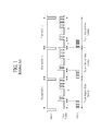
- FIG. 1 is a timing chart showing signals during a display period and a touch period based on one vertical sync signal, in a general display device with an integrated touch screen.
- a display period D and a touch period T are time-divided and driven according to a data enable signal during one frame based on one vertical sync signal.
- Embodiments of the present invention relate to a display device with input system and method for driving the same. Accordingly, embodiments of the present invention are directed to a display device with an integrated touch screen and a method of driving the same that substantially obviate one or more problems due to limitations and disadvantages of the related art.
- An aspect of embodiments is to provide a display device with an integrated touch screen that performs display driving and touch driving according to a horizontal sync signal.
- a display device including an integrated touch screen, including: a panel including a plurality of electrodes, the electrodes being divided into n number of groups, where n is an integer greater than or equal to two, a data driver configured to: convert data, inputted from a timing controller, into data voltages, and supply the data voltages to a plurality of data lines, respectively, a gate driver configured to sequentially supply a gate signal to a plurality of gate lines, allowing the data voltages to be respectively applied to a plurality of pixels of the panel, during a high logic period of a horizontal sync signal, and a touch sensing unit configured to apply a touch scan signal to one of the n groups every n or more low logic periods of the horizontal sync signal, the touch scan signal being applied to each of the n groups at least one time, during one frame.
- a method of driving a display device including an integrated touch screen including: converting, by a data driver, data inputted from a timing controller into data voltages, supplying, by the data driver, the data voltages to a plurality of data lines, respectively, sequentially supplying, by a gate driver, a gate signal to a plurality of gate lines, allowing the data voltages to be respectively applied to a plurality of pixels of a panel, during a high logic period of a horizontal sync signal, the panel including a plurality of electrodes, the electrodes being divided into n number of groups, where n is an integer greater than or equal to two, and applying, by a touch sensing unit, a touch scan signal to one of the n groups every n or more low logic periods of the horizontal sync signal, the touch scan signal being applied to each of the n groups at least one time, during one frame.
- a method of driving a display device including an integrated touch screen, including a panel including a plurality of electrodes that are divided into n number of groups, where n is an integer greater than or equal to two, and a touch sensing unit, the method including: applying data voltages to a plurality of pixels of the panel, during a high logic period of a horizontal sync signal, and applying, by the touch sensing unit, a touch scan signal to one of the n groups every n or more low logic periods of the horizontal sync signal, the touch scan signal being applied to each of the n groups at least one time, during one frame.
- FIG. 1 is a timing chart showing signals in a display driving method and a touch driving method based on one vertical sync signal in a related art display device with an integrated touch screen.
- FIG. 2 is a block diagram illustrating a configuration of a display device with an integrated touch screen according to an embodiment.
- FIG. 3 is a schematic diagram illustrating a panel and touch sensing unit of a display device with an integrated touch screen according to an embodiment.
- FIG. 4 is a timing chart showing signals in a driving method based on one horizontal sync signal of a display device with an integrated touch screen according to an embodiment.
- FIGS. 5 and 6 are timing charts showing signals in another driving method based on one horizontal sync signal of the display device with an integrated touch screen according to an embodiment.
- a plurality of electrodes may be divided into n number of groups, and a touch scan signal may be sequentially applied to the n groups.
- a method in which the electrodes are divided into three groups the below description will be made for a method in which the electrodes are divided into three groups. Therefore, embodiments are not limited to the method where the electrodes are divided into the three groups, and the electrodes may be divided into two groups or four or more groups.
- FIG. 2 is a block diagram illustrating a configuration of a display device with an integrated touch screen according to an embodiment.
- FIG. 3 is a schematic diagram illustrating a panel and touch sensing unit of a display device with an integrated touch screen according to an embodiment.
- the display device with an integrated touch screen may include a panel 100 , a touch sensing unit 200 , a gate driver 300 , a data driver 400 , a timing controller 500 , and a system 600 .
- the panel 100 may include a built-in touch screen (not shown), which may sense a user's touch position.
- the touch screen may be an in-cell type touch screen using a self-capacitive type.
- the panel 100 may be configured in a structure in which a liquid crystal layer is formed between two substrates.
- a plurality of gate lines, a plurality of data lines intersecting the gate lines, a plurality of thin film transistors (TFTs) formed in respective intersection portions between the data lines and the gate lines, and a plurality of pixels formed in a matrix type by an intersection structure between the data lines and the gate lines may be disposed in a lower substrate of the panel 100 .
- the panel 100 may include a plurality of electrodes 120 and a plurality of lines 130 .
- the electrodes may operate as pixel electrodes formed in the respective pixels and common electrodes for driving liquid crystal.
- the electrodes 120 may operate as touch electrodes for sensing a touch position.
- the electrodes 120 may be divided into a total of three groups 110 , including first to third groups 111 to 113 , in the panel 100 .
- the electrodes 120 may be formed in a block type of groups 110 , and, in one example, may be divided and formed in a gate-line direction.
- the plurality of lines 130 may connect the electrodes 120 and the touch sensing unit 200 .
- the lines 130 may transfer a touch scan signal applied from the touch sensing unit 200 to the electrodes 120 of the panel 100 , respectively.
- the lines 130 may transfer the capacitive changes received from the electrodes 120 of the panel 100 to the touch sensing unit 200 , respectively.
- the touch sensing unit 200 may apply the touch scan signal to one of the three groups every three or more low logic periods of a horizontal sync signal, in which case the touch sensing unit 200 may apply the touch scan signal to the three groups at least one time.
- the touch sensing unit 200 may apply the touch scan signal to one of the three groups.
- the touch sensing unit 200 may apply the touch scan signal to another group (to which the touch scan signal is not applied) of the three groups.
- the touch sensing unit 200 may apply the touch scan signal to the other group (to which the touch scan signal is not applied) of the three groups.
- the touch sensing unit 200 of the display device with an integrated touch screen may apply the touch scan signal to the group (which has received the touch scan signal for the first time) of the three groups, during a selected fourth low logic period.
- the touch sensing unit 200 may allow the touch scan signal to be applied to the three divided groups at least one time.
- the touch scan signal is applied to the three groups during the three or more low logic periods.
- the touch scan signal may be applied to the two or more groups during the two low logic periods, or the touch scan signal may be applied to the four or more groups during the four or more low logic periods.
- display driving and touch driving may not be divided and performed according to a data enable signal during one frame based on one vertical sync signal, and may be temporally divided and performed in units of one line based on one horizontal sync signal.
- a touch report rate may become higher by increasing the number of times the touch scan signal is applied to the electrodes 120 of the panel 100 during one frame, and thus touch input or dragging may be more accurately sensed.
- the touch sensing unit 200 may include a touch scan signal generator that may generate the touch scan signal to be supplied to the plurality of electrodes of the panel 100 for touch sensing.
- the touch sensing unit 200 may be implemented as a plurality of touch sensing units, in which case each of the touch sensing units may include the touch scan signal generator.
- the touch scan signal may be a touch driving voltage, which may have a level higher than that of a common voltage that is applied to the plurality of electrodes of the panel 100 for display driving.
- the touch driving voltage may have a low level equal to that of the common voltage, and a high level higher than that of the common voltage.
- the touch sensing unit 200 may receive touch sensing signals from the plurality of electrodes 120 to calculate touch coordinates between low logic periods in which the touch scan signal is applied, sensing a user's touch.
- the touch sensing unit 200 may calculate touch coordinates in a section from a time (for which the touch scan signal is applied to one group during a selected low logic period) to a time for which the touch scan signal is applied to another group during a next-selected low logic period, sensing a touch.
- the calculated touch coordinates may be transferred to the system 600 , and may enable the panel 100 to detect a user's touch coordinates.
- the display device with an integrated touch screen may further include a plurality of switching units 210 .
- Each of the switching units 210 may perform switching in order for the touch scan signal (which is outputted from the touch sensing unit 200 ) to be applied to one of the three groups.
- each of the switching units 210 may perform a switching function that allows the touch scan signal, generated by the touch sensing unit 200 , to be applied to one of the first to third groups 111 to 113 into which the plurality of electrodes 120 are divided.
- each of the switching units 210 may perform switching in order for the touch scan signal to be applied to one of the three groups 111 to 113 of the panel 100 .
- the switching unit 210 may perform switching in order for the touch scan signal to be applied to another group (to which the touch scan signal is not applied) of the three groups 111 to 113 of the panel 100 .
- the switching unit 210 may perform switching in order for the touch scan signal to be applied to the other group (to which the touch scan signal is not applied) of the three groups 111 to 113 of the panel 100 .
- Each of the switching units 210 of the display device with an integrated touch screen may apply the touch scan signal to the group (which has received the touch scan signal for the first time) of the three groups, during a selected fourth low logic period.
- each of the switching units 210 may be connected to one electrode for each group.
- each of the switching units 210 may be a signal distributor, such as a 1:3 demultiplexer.
- the plurality of switching units 210 may be included in the touch sensing unit 200 , and may perform switching in order for the touch scan signal, outputted from the touch sensing unit 200 , to be applied to one of the three groups.
- the gate driver 300 may apply a gate signal to a pixel of the panel 100 during a high logic period of the horizontal sync signal.
- the gate driver 300 may sequentially apply the gate signal to a plurality of gate lines GL 1 to GLm, and may select the respective lines of the panel 100 which receive data voltages.
- the pixels of the panel 100 may be charged with respective data voltages inputted from the data driver 400 during the high logic period of the horizontal sync signal Hsync in response to the gate signal, and may hold the respective data voltages during the low logic period of the horizontal sync signal Hsync.
- the gate driver 300 may shift a gate start pulse GSP transferred from the timing controller 500 according to a gate shift clock GSC, may sequentially supply the gate signal having a gate-on voltage (Von), and may supply a gate-off voltage (Voff) to the gate lines GL 1 to GLm during the other period for which the gate signal having the gate-on voltage is not supplied.
- the gate signal may include a gate scan signal.
- the gate driver 300 may be provided independently from the panel 100 , and may be electrically connected to the panel 100 in various types. However, the gate driver 300 may be provided in a gate-in panel type in which the gate driver 300 is disposed inside the panel 100 , in which case a start signal VST and a gate clock GCLK may be used as gate control signals for controlling the gate driver 300 .
- the data driver 400 may convert data, e.g., red, green, and blue (RGB) data, inputted from the timing controller 500 , into data voltages and may output the data voltages.
- the data voltages outputted from the data driver 400 may be supplied to a plurality of data lines DL 1 to DLn, respectively.
- the data driver 400 may shift a source start pulse SSP from the timing controller 500 to generate a sampling signal according to a source shift clock SSC.
- the data driver 400 may latch pixel data, e.g., RGB data (e.g., image data) according to the sampling signal, and may convert the latched pixel data into data signals, and then may supply the data signals to the data lines in units of a horizontal line in response to a source output enable signal SOE, respectively.
- Each of the data signals may include a data voltage.
- the data driver 400 may include a sampling signal generating unit, a latch unit, a digital-to-analog (D/A) converter, and an output buffer.
- D/A digital-to-analog
- the timing controller 500 may receive timing signals, such as the vertical sync signal Vsync, the horizontal sync signal Hsync, the data enable signal DE, and a main clock CLK, from the system 600 to generate control signals GCS and DCS for controlling the respective operational timings of the gate driver 300 and data driver 400 . Also, the timing controller 500 may realign data, e.g., RGB data, inputted from the system 600 to output the realigned data, e.g., RGB data, to the data driver 400 .
- timing signals such as the vertical sync signal Vsync, the horizontal sync signal Hsync, the data enable signal DE, and a main clock CLK
- the timing controller 500 may realign data, e.g., RGB data, inputted from the system 600 to output the realigned data, e.g., RGB data, to the data driver 400 .
- the vertical sync signal Vsync may be a signal that defines one frame period. Therefore, one period of the vertical sync signal may be set as one frame period.
- the horizontal sync signal Hsync may be a signal that defines one horizontal period for applying data to pixels corresponding to one line in a pixel array of the panel 100 . Accordingly, one period of the horizontal sync signal may be set as one horizontal period, and one horizontal period may be calculated by dividing one frame period by the number of lines formed in the panel 100 .
- the data enable signal DE may be a signal that defines a period for which valid data are inputted, and one period may be set as one horizontal period identically to the horizontal sync signal.
- the main clock CLK may be synchronized with the bits of data, e.g., RGB data.
- the system 600 may transmit data, e.g., RGB data, and the timing signals Vsync, Hsync, DE, and MCLK to the timing controller 500 .
- data e.g., RGB data
- the data, e.g., RGB data, for one line may be transmitted to the timing controller 500 in synchronization with the high logic period of the horizontal sync signal, but may not be transmitted to the timing controller 500 during the low logic period of the horizontal sync signal.
- the timing signal Vsync may be the vertical sync signal
- the timing signal Hsync may be the horizontal sync signal.
- system 600 may execute a program associated with touch coordinate values such that the panel 100 recognizes the touch coordinates transferred from the touch sensing unit 200 .
- the display device with an integrated touch screen may sequentially drive a plurality of electrodes for touch sensing in units of a group, and may supply the touch scan signal for touch sensing to a plurality of electrodes by group according to the horizontal sync signal. This will be described in more detail with reference to FIGS. 2 and 4 .
- FIG. 4 is a timing chart showing signals in a driving method based on one horizontal sync signal of a display device with an integrated touch screen according to an embodiment.
- the gate driver 300 may apply data voltages to the pixels of the panel 100 during the high logic period of the horizontal sync signal.
- the gate drive 300 may sequentially supply the gate signal to the gate lines GL 1 to GLm, and may select the respective lines of the panel 100 which receive data voltages.
- the pixels of the panel 100 may be charged with respective data voltages inputted from the data driver 400 during the high logic period of the horizontal sync signal Hsync in response to the gate signal, and may hold the respective data voltages during the low logic period of the horizontal sync signal Hsync.
- the touch sensing unit 200 may apply the touch scan signal to one of the three groups during the three low logic periods of the horizontal sync signal Hsync, in which case the touch sensing unit 200 may apply the touch scan signal to the three groups at least one time.
- the touch sensing unit 200 may apply the touch scan signal to a plurality of electrodes included in the first group during the selected first low logic period of the horizontal sync signal, and may apply the touch scan signal to a plurality of electrodes included in the second group during the selected second low logic period of the horizontal sync signal. Also, the touch sensing unit 200 may apply the touch scan signal to a plurality of electrodes included in the third group during the selected third low logic period of the horizontal sync signal.
- the touch sensing unit 200 may receive respective touch sensing signals from the plurality of electrodes to calculate touch coordinates between low logic periods for which the touch scan signal is applied.
- the touch sensing unit 200 may calculate sensed touch coordinates of the first group with the touch scan signal that is applied thereto during a selected first low logic period, in a section t 1 from a time (for which the touch scan signal is applied to the first group during the selected first low logic period) to a time for which the touch scan signal is applied during a selected second low logic period.
- the touch sensing unit 200 may calculate sensed touch coordinates of the second group with the touch scan signal that is applied thereto during the selected second low logic period, in a section t 2 from a time (for which the touch scan signal is applied to the second group during the selected second low logic period) to a time for which the touch scan signal is applied during a selected third low logic period.
- the touch sensing unit 200 may calculate sensed touch coordinates of the third group with the touch scan signal that is applied thereto during the selected third low logic period, in a section t 3 from a time (for which the touch scan signal is applied to the third group during the selected third low logic period) to a time for which the touch scan signal is applied during a selected first low logic period of a next frame.
- a display period and a touch period may be divided with the horizontal sync signal Hsync instead of the data enable signal DE, during one frame.
- a frequency at which new data are transferred to all pixels of a panel is called a “display frame rate,” and a frequency at which touch data obtained in a touch screen are transferred to a system is called a “touch frame rate.” That is, as the touch report rate becomes higher than the display frame rate, a speed at which coordinates inputted to a touch panel are transmitted may become faster, and thus touch sensitivity a user feels may increase, and a touch input can be more accurately expressed.
- the above-described features will be described with reference to FIGS. 5 and 6 .
- FIGS. 5 and 6 are timing charts showing signals in a driving method based on one horizontal sync signal of the display device with an integrated touch screen according to an embodiment.
- the gate driver 300 may apply gate signals to the pixels of the panel 100 during the high logic period of the horizontal sync signal.
- the gate drive 300 may sequentially supply the gate signal to the gate lines GL 1 to GLm, and may select the respective lines of the panel 100 which receive data voltages.
- the pixels of the panel 100 may be charged with respective data voltages inputted from the data driver 400 during the high logic period of the horizontal sync signal Hsync in response to the gate signal, and may hold the respective data voltages during the low logic period of the horizontal sync signal Hsync.
- the touch sensing unit 200 may apply the touch scan signal to one of the three groups during the four low logic periods of the horizontal sync signal Hsync, in which case the touch sensing unit 200 may apply the touch scan signal to the three groups at least one time.
- the touch sensing unit 200 may apply the touch scan signal to a plurality of electrodes included in the first group during the selected first low logic period of the horizontal sync signal, and may apply the touch scan signal to a plurality of electrodes included in the second group during the selected second low logic period of the horizontal sync signal. Also, the touch sensing unit 200 may apply the touch scan signal to a plurality of electrodes included in the third group during the selected third low logic period of the horizontal sync signal, and again may apply the touch scan signal to the plurality of electrodes included in the first group during the selected fourth low logic period of the horizontal sync signal.
- the touch sensing unit 200 may receive respective touch sensing signals from the plurality of electrodes to calculate touch coordinates between low logic periods for which the touch scan signal is applied.
- the touch sensing unit 200 may calculate sensed touch coordinates of the first group with the touch scan signal that is applied thereto during a selected first low logic period, in a section t 1 from a time (for which the touch scan signal is applied to the first group during the selected first low logic period) to a time for which touch scan signal is applied during a selected second low logic period.
- the touch sensing unit 200 may calculate sensed touch coordinates of the second group with the touch scan signal that is applied thereto during the selected second low logic period, in a section t 2 from a time (for which the touch scan signal is applied to the second group during the selected second low logic period) to a time for which touch scan signal is applied during a selected third low logic period.
- the touch sensing unit 200 may calculate sensed touch coordinates of the third group with the touch scan signal that is applied thereto during the selected third low logic period, in a section t 3 from a time (for which the touch scan signal is applied to the third group during the selected third low logic period) to a time for which the touch scan signal is applied during a selected fourth low logic period.
- the touch sensing unit 200 may calculate sensed touch coordinates of the first group with the touch scan signal that is applied thereto during the selected fourth low logic period, in a section t 4 from a time (for which the touch scan signal is applied to the fourth group during the selected fourth low logic period) to a time for which the touch scan signal is applied during a selected first low logic period of a next frame.
- the display frame rate of the display device with an integrated touch screen may be, e.g., 60 Hz.
- a driving method based on one horizontal sync signal may transmit touch sensing data (which are obtained in the touch screen) to the system 600 four times, thus securing the touch report rate of, e.g., 80 Hz.
- a speed at which coordinates inputted to a touch panel are transmitted may become faster, and thus touch sensitivity a user feels may increase, and a touch input can be more accurately expressed.
- the gate driver 300 applies gate signals to the pixels of the panel 100 during the high logic period of the horizontal sync signal.
- the gate drive 300 may sequentially supply the gate signal to the gate lines GL 1 to GLm, and may select the respective lines of the panel 100 which receive data voltages.
- the pixels of the panel 100 may be charged with respective data voltages inputted from the data driver 400 during the high logic period of the horizontal sync signal Hsync in response to the gate signal, and may hold the respective data voltages during the low logic period of the horizontal sync signal Hsync.
- the touch sensing unit 200 may apply the touch scan signal to one of the three groups during the six low logic periods of the horizontal sync signal Hsync, in which case the touch sensing unit 200 may apply the touch scan signal to the three groups at least one time.
- the touch sensing unit 200 may apply the touch scan signal to a plurality of electrodes included in the first group during the selected first low logic period of the horizontal sync signal, may apply the touch scan signal to a plurality of electrodes included in the second group during the selected second low logic period of the horizontal sync signal, may apply the touch scan signal to a plurality of electrodes included in the third group during the selected third low logic period of the horizontal sync signal, and may again apply the touch scan signal to the plurality of electrodes included in the first group during the selected fourth low logic period of the horizontal sync signal.
- the touch sensing unit 200 may again apply the touch scan signal to the plurality of electrodes included in the second group during the selected fifth low logic period of the horizontal sync signal, and may again apply the touch scan signal to the plurality of electrodes included in the third group during the selected sixth low logic period of the horizontal sync signal.
- the touch sensing unit 200 may receive respective touch sensing signals from the plurality of electrodes to calculate touch coordinates between low logic periods for which the touch scan signal is applied.
- the touch sensing unit 200 may calculate touch coordinates of the first group in a section t 1 , and may calculate touch coordinates of the second group in a section t 2 .
- the touch sensing unit 200 may calculate touch coordinates of the third group in a section t 3 , and may calculate touch coordinates of the first group in a section t 4 .
- the touch sensing unit 200 may calculate touch coordinates of the second group in a section t 5 , and may calculate touch coordinates of the third group in a section t 6 .
- the display frame rate of the display device with an integrated touch screen may be, e.g., 60 Hz.
- another driving method based on one horizontal sync signal may transmit touch sensing data (which are obtained in the touch screen) to the system 600 six times, thus securing the touch report rate of, e.g., 120 Hz.
- the display driving and touch driving of the in-cell type self-capacitive touch screen may not be divided in units of one frame based on one vertical sync signal but may be divided and performed in units of one line based on one horizontal sync signal.
- touch input or dragging can be more accurately detected by increasing a touch report rate.
Landscapes
- Engineering & Computer Science (AREA)
- Physics & Mathematics (AREA)
- Theoretical Computer Science (AREA)
- General Engineering & Computer Science (AREA)
- General Physics & Mathematics (AREA)
- Human Computer Interaction (AREA)
- Nonlinear Science (AREA)
- Chemical & Material Sciences (AREA)
- Crystallography & Structural Chemistry (AREA)
- Optics & Photonics (AREA)
- Mathematical Physics (AREA)
- Computer Hardware Design (AREA)
- Microelectronics & Electronic Packaging (AREA)
- Geometry (AREA)
- Control Of Indicators Other Than Cathode Ray Tubes (AREA)
- Liquid Crystal Display Device Control (AREA)
Abstract
Description
- This application claims the benefit under 35 U.S.C. §119(a) of Korean Patent Application No. 10-2012-0095535, filed on Aug. 30, 2012, in the Korean Intellectual Property Office, the entire disclosure of which is incorporated by reference herein for all purposes.
- 1. Technical Field
- The following description relates to a display device, and more particularly, to a display device with an integrated touch screen and a method of driving the same.
- 2. Discussion of the Related Art
- Touch screens are a type of input device that is included in image display devices such as Liquid Crystal Displays (LCDs), Field Emission Displays (FEDs), Plasma Display Panels (PDPs), Electroluminescent Displays (ELDs), and Electrophoretic Displays (EPDs), and allows a user to input predetermined information by applying a pressure (i.e., pressing or touching) to a touch sensor of a touch screen while looking at the image display device.
- Particularly, the demand of display devices with integrated in-cell type touch screen, which include a plurality of built-in elements configuring the touch screen for slimming portable terminals such as smart phones and tablet Personal Computers (PCs), is recently increasing.
- General display devices with integrated in-cell type touch screen transmit touch data to a system once every one vertical sync signal (Vsync) that defines one frame period.
- Hereinafter, the driving of a related art display device with integrated in-cell type touch screen will be described with reference to
FIG. 1 . -
FIG. 1 is a timing chart showing signals during a display period and a touch period based on one vertical sync signal, in a general display device with an integrated touch screen. - In a general display device with integrated in-cell type self-capacitive touch screen, as shown in
FIG. 1 , a display period D and a touch period T are time-divided and driven according to a data enable signal during one frame based on one vertical sync signal. - Embodiments of the present invention relate to a display device with input system and method for driving the same. Accordingly, embodiments of the present invention are directed to a display device with an integrated touch screen and a method of driving the same that substantially obviate one or more problems due to limitations and disadvantages of the related art.
- An aspect of embodiments is to provide a display device with an integrated touch screen that performs display driving and touch driving according to a horizontal sync signal.
- Advantages, objects, and features of the disclosure will be set forth in part in the description which follows and in part will become apparent to those having ordinary skill in the art upon examination of the following or may be learned from practice of the invention. The objectives and other advantages of the invention may be realized and attained by the structure particularly pointed out in the written description and claims hereof as well as the appended drawings.
- To achieve these objects and other advantages and in accordance with the purpose according to one aspect of the invention, there is provided a display device including an integrated touch screen, including: a panel including a plurality of electrodes, the electrodes being divided into n number of groups, where n is an integer greater than or equal to two, a data driver configured to: convert data, inputted from a timing controller, into data voltages, and supply the data voltages to a plurality of data lines, respectively, a gate driver configured to sequentially supply a gate signal to a plurality of gate lines, allowing the data voltages to be respectively applied to a plurality of pixels of the panel, during a high logic period of a horizontal sync signal, and a touch sensing unit configured to apply a touch scan signal to one of the n groups every n or more low logic periods of the horizontal sync signal, the touch scan signal being applied to each of the n groups at least one time, during one frame.
- In another aspect, there is provided a method of driving a display device including an integrated touch screen, the method including: converting, by a data driver, data inputted from a timing controller into data voltages, supplying, by the data driver, the data voltages to a plurality of data lines, respectively, sequentially supplying, by a gate driver, a gate signal to a plurality of gate lines, allowing the data voltages to be respectively applied to a plurality of pixels of a panel, during a high logic period of a horizontal sync signal, the panel including a plurality of electrodes, the electrodes being divided into n number of groups, where n is an integer greater than or equal to two, and applying, by a touch sensing unit, a touch scan signal to one of the n groups every n or more low logic periods of the horizontal sync signal, the touch scan signal being applied to each of the n groups at least one time, during one frame.
- In another aspect, there is provided a method of driving a display device including an integrated touch screen, including a panel including a plurality of electrodes that are divided into n number of groups, where n is an integer greater than or equal to two, and a touch sensing unit, the method including: applying data voltages to a plurality of pixels of the panel, during a high logic period of a horizontal sync signal, and applying, by the touch sensing unit, a touch scan signal to one of the n groups every n or more low logic periods of the horizontal sync signal, the touch scan signal being applied to each of the n groups at least one time, during one frame.
- It is to be understood that both the foregoing general description and the following detailed description are examples and explanatory and are intended to provide further explanation of embodiments of the invention as claimed.
- The accompanying drawings, which are included to provide a further understanding of the invention and are incorporated in and constitute a part of this specification, illustrate implementations of the invention and together with the description serve to explain the principles of the invention.
-
FIG. 1 is a timing chart showing signals in a display driving method and a touch driving method based on one vertical sync signal in a related art display device with an integrated touch screen. -
FIG. 2 is a block diagram illustrating a configuration of a display device with an integrated touch screen according to an embodiment. -
FIG. 3 is a schematic diagram illustrating a panel and touch sensing unit of a display device with an integrated touch screen according to an embodiment. -
FIG. 4 is a timing chart showing signals in a driving method based on one horizontal sync signal of a display device with an integrated touch screen according to an embodiment. -
FIGS. 5 and 6 are timing charts showing signals in another driving method based on one horizontal sync signal of the display device with an integrated touch screen according to an embodiment. - Throughout the drawings and the detailed description, unless otherwise described, the same drawing reference numerals should be understood to refer to the same elements, features, and structures. The relative size and depiction of these elements may be exaggerated for clarity, illustration, and convenience.
- Reference will now be made in detail to embodiments of the present invention, examples of which are illustrated in the accompanying drawings. In the following description, when a detailed description of well-known functions or configurations related to this document is determined to unnecessarily cloud a gist of the invention, the detailed description thereof will be omitted. The progression of processing steps and/or operations described is an example; however, the sequence of steps and/or operations is not limited to that set forth herein and may be changed as is known in the art, with the exception of steps and/or operations necessarily occurring in a certain order. Like reference numerals designate like elements throughout. Names of the respective elements used in the following explanations are selected only for convenience of writing the specification and may be thus different from those used in actual products.
- In a display device with an integrated touch screen according to an embodiment, a plurality of electrodes may be divided into n number of groups, and a touch scan signal may be sequentially applied to the n groups. However, for convenience of a description, the below description will be made for a method in which the electrodes are divided into three groups. Therefore, embodiments are not limited to the method where the electrodes are divided into the three groups, and the electrodes may be divided into two groups or four or more groups.
-
FIG. 2 is a block diagram illustrating a configuration of a display device with an integrated touch screen according to an embodiment.FIG. 3 is a schematic diagram illustrating a panel and touch sensing unit of a display device with an integrated touch screen according to an embodiment. - As illustrated in
FIG. 2 , the display device with an integrated touch screen according to an embodiment may include apanel 100, atouch sensing unit 200, agate driver 300, adata driver 400, atiming controller 500, and asystem 600. - The
panel 100 may include a built-in touch screen (not shown), which may sense a user's touch position. In one example, the touch screen may be an in-cell type touch screen using a self-capacitive type. - The
panel 100 may be configured in a structure in which a liquid crystal layer is formed between two substrates. In one example, a plurality of gate lines, a plurality of data lines intersecting the gate lines, a plurality of thin film transistors (TFTs) formed in respective intersection portions between the data lines and the gate lines, and a plurality of pixels formed in a matrix type by an intersection structure between the data lines and the gate lines may be disposed in a lower substrate of thepanel 100. - The
panel 100, as illustrated inFIG. 3 , may include a plurality ofelectrodes 120 and a plurality oflines 130. - In response to a common voltage being applied for display driving of the
panel 100, the electrodes may operate as pixel electrodes formed in the respective pixels and common electrodes for driving liquid crystal. In response to a touch scan signal being applied for touch sensing, theelectrodes 120 may operate as touch electrodes for sensing a touch position. - The
electrodes 120 may be divided into a total of threegroups 110, including first tothird groups 111 to 113, in thepanel 100. Theelectrodes 120 may be formed in a block type ofgroups 110, and, in one example, may be divided and formed in a gate-line direction. - The plurality of
lines 130 may connect theelectrodes 120 and thetouch sensing unit 200. For example, thelines 130 may transfer a touch scan signal applied from thetouch sensing unit 200 to theelectrodes 120 of thepanel 100, respectively. Thelines 130 may transfer the capacitive changes received from theelectrodes 120 of thepanel 100 to thetouch sensing unit 200, respectively. - As illustrated in
FIG. 3 , thetouch sensing unit 200 may apply the touch scan signal to one of the three groups every three or more low logic periods of a horizontal sync signal, in which case thetouch sensing unit 200 may apply the touch scan signal to the three groups at least one time. - For example, during a first low logic period selected from among the three or more low logic periods of the horizontal sync signal, the
touch sensing unit 200 may apply the touch scan signal to one of the three groups. During a second low logic period selected from among the three or more low logic periods of the horizontal sync signal, thetouch sensing unit 200 may apply the touch scan signal to another group (to which the touch scan signal is not applied) of the three groups. During a third low logic period selected from among the three or more low logic periods of the horizontal sync signal, thetouch sensing unit 200 may apply the touch scan signal to the other group (to which the touch scan signal is not applied) of the three groups. - The
touch sensing unit 200 of the display device with an integrated touch screen according to an embodiment may apply the touch scan signal to the group (which has received the touch scan signal for the first time) of the three groups, during a selected fourth low logic period. In other words, by repeatedly performing the above-described operation during each of low logic periods after the selected fourth low logic period, thetouch sensing unit 200 may allow the touch scan signal to be applied to the three divided groups at least one time. - In the display device with an integrated touch screen according to an embodiment, a case in which the touch scan signal is applied to the three groups during the three or more low logic periods has been described above as an example, but embodiments are not limited thereto. As another example, the touch scan signal may be applied to the two or more groups during the two low logic periods, or the touch scan signal may be applied to the four or more groups during the four or more low logic periods.
- As described above, display driving and touch driving may not be divided and performed according to a data enable signal during one frame based on one vertical sync signal, and may be temporally divided and performed in units of one line based on one horizontal sync signal. Also, a touch report rate may become higher by increasing the number of times the touch scan signal is applied to the
electrodes 120 of thepanel 100 during one frame, and thus touch input or dragging may be more accurately sensed. - The
touch sensing unit 200 according to an embodiment may include a touch scan signal generator that may generate the touch scan signal to be supplied to the plurality of electrodes of thepanel 100 for touch sensing. - Alternatively, the
touch sensing unit 200 may be implemented as a plurality of touch sensing units, in which case each of the touch sensing units may include the touch scan signal generator. The touch scan signal may be a touch driving voltage, which may have a level higher than that of a common voltage that is applied to the plurality of electrodes of thepanel 100 for display driving. In one example, the touch driving voltage may have a low level equal to that of the common voltage, and a high level higher than that of the common voltage. - Moreover, the
touch sensing unit 200 according to an embodiment may receive touch sensing signals from the plurality ofelectrodes 120 to calculate touch coordinates between low logic periods in which the touch scan signal is applied, sensing a user's touch. - For example, the
touch sensing unit 200 may calculate touch coordinates in a section from a time (for which the touch scan signal is applied to one group during a selected low logic period) to a time for which the touch scan signal is applied to another group during a next-selected low logic period, sensing a touch. For example, the calculated touch coordinates may be transferred to thesystem 600, and may enable thepanel 100 to detect a user's touch coordinates. - The display device with an integrated touch screen according to an embodiment, as illustrated in
FIG. 3 , may further include a plurality of switchingunits 210. - Each of the switching
units 210 may perform switching in order for the touch scan signal (which is outputted from the touch sensing unit 200) to be applied to one of the three groups. - For example, each of the switching
units 210 may perform a switching function that allows the touch scan signal, generated by thetouch sensing unit 200, to be applied to one of the first tothird groups 111 to 113 into which the plurality ofelectrodes 120 are divided. - In other words, during the selected first low logic period of the horizontal sync signal, each of the switching
units 210 may perform switching in order for the touch scan signal to be applied to one of the threegroups 111 to 113 of thepanel 100. During the selected second low logic period of the horizontal sync signal, theswitching unit 210 may perform switching in order for the touch scan signal to be applied to another group (to which the touch scan signal is not applied) of the threegroups 111 to 113 of thepanel 100. During the selected third low logic period of the horizontal sync signal, theswitching unit 210 may perform switching in order for the touch scan signal to be applied to the other group (to which the touch scan signal is not applied) of the threegroups 111 to 113 of thepanel 100. - Each of the switching
units 210 of the display device with an integrated touch screen according to an embodiment may apply the touch scan signal to the group (which has received the touch scan signal for the first time) of the three groups, during a selected fourth low logic period. - For example, each of the switching
units 210 may be connected to one electrode for each group. In one example, each of the switchingunits 210 according to an embodiment may be a signal distributor, such as a 1:3 demultiplexer. - Moreover, the plurality of switching
units 210 may be included in thetouch sensing unit 200, and may perform switching in order for the touch scan signal, outputted from thetouch sensing unit 200, to be applied to one of the three groups. - With reference again to
FIG. 2 , thegate driver 300 may apply a gate signal to a pixel of thepanel 100 during a high logic period of the horizontal sync signal. - For example, the
gate driver 300 may sequentially apply the gate signal to a plurality of gate lines GL1 to GLm, and may select the respective lines of thepanel 100 which receive data voltages. The pixels of thepanel 100 may be charged with respective data voltages inputted from thedata driver 400 during the high logic period of the horizontal sync signal Hsync in response to the gate signal, and may hold the respective data voltages during the low logic period of the horizontal sync signal Hsync. - For example, the
gate driver 300 may shift a gate start pulse GSP transferred from thetiming controller 500 according to a gate shift clock GSC, may sequentially supply the gate signal having a gate-on voltage (Von), and may supply a gate-off voltage (Voff) to the gate lines GL1 to GLm during the other period for which the gate signal having the gate-on voltage is not supplied. In one example, the gate signal may include a gate scan signal. - The
gate driver 300 may be provided independently from thepanel 100, and may be electrically connected to thepanel 100 in various types. However, thegate driver 300 may be provided in a gate-in panel type in which thegate driver 300 is disposed inside thepanel 100, in which case a start signal VST and a gate clock GCLK may be used as gate control signals for controlling thegate driver 300. - The
data driver 400 may convert data, e.g., red, green, and blue (RGB) data, inputted from thetiming controller 500, into data voltages and may output the data voltages. The data voltages outputted from thedata driver 400 may be supplied to a plurality of data lines DL1 to DLn, respectively. - In other words, the
data driver 400 may shift a source start pulse SSP from thetiming controller 500 to generate a sampling signal according to a source shift clock SSC. Thedata driver 400 may latch pixel data, e.g., RGB data (e.g., image data) according to the sampling signal, and may convert the latched pixel data into data signals, and then may supply the data signals to the data lines in units of a horizontal line in response to a source output enable signal SOE, respectively. Each of the data signals may include a data voltage. - The
data driver 400 may include a sampling signal generating unit, a latch unit, a digital-to-analog (D/A) converter, and an output buffer. - The
timing controller 500 may receive timing signals, such as the vertical sync signal Vsync, the horizontal sync signal Hsync, the data enable signal DE, and a main clock CLK, from thesystem 600 to generate control signals GCS and DCS for controlling the respective operational timings of thegate driver 300 anddata driver 400. Also, thetiming controller 500 may realign data, e.g., RGB data, inputted from thesystem 600 to output the realigned data, e.g., RGB data, to thedata driver 400. - For example, the vertical sync signal Vsync may be a signal that defines one frame period. Therefore, one period of the vertical sync signal may be set as one frame period. Also, the horizontal sync signal Hsync may be a signal that defines one horizontal period for applying data to pixels corresponding to one line in a pixel array of the
panel 100. Accordingly, one period of the horizontal sync signal may be set as one horizontal period, and one horizontal period may be calculated by dividing one frame period by the number of lines formed in thepanel 100. The data enable signal DE may be a signal that defines a period for which valid data are inputted, and one period may be set as one horizontal period identically to the horizontal sync signal. The main clock CLK may be synchronized with the bits of data, e.g., RGB data. - The
system 600 may transmit data, e.g., RGB data, and the timing signals Vsync, Hsync, DE, and MCLK to thetiming controller 500. For example, the data, e.g., RGB data, for one line may be transmitted to thetiming controller 500 in synchronization with the high logic period of the horizontal sync signal, but may not be transmitted to thetiming controller 500 during the low logic period of the horizontal sync signal. The timing signal Vsync may be the vertical sync signal, and the timing signal Hsync may be the horizontal sync signal. - Moreover, the
system 600 may execute a program associated with touch coordinate values such that thepanel 100 recognizes the touch coordinates transferred from thetouch sensing unit 200. - The display device with an integrated touch screen according to an embodiment may sequentially drive a plurality of electrodes for touch sensing in units of a group, and may supply the touch scan signal for touch sensing to a plurality of electrodes by group according to the horizontal sync signal. This will be described in more detail with reference to
FIGS. 2 and 4 . -
FIG. 4 is a timing chart showing signals in a driving method based on one horizontal sync signal of a display device with an integrated touch screen according to an embodiment. - In the method of driving the display device with an integrated touch screen according to an embodiment, as shown in
FIG. 4 , thegate driver 300 may apply data voltages to the pixels of thepanel 100 during the high logic period of the horizontal sync signal. - For example, the
gate drive 300 may sequentially supply the gate signal to the gate lines GL1 to GLm, and may select the respective lines of thepanel 100 which receive data voltages. The pixels of thepanel 100 may be charged with respective data voltages inputted from thedata driver 400 during the high logic period of the horizontal sync signal Hsync in response to the gate signal, and may hold the respective data voltages during the low logic period of the horizontal sync signal Hsync. - Subsequently, the
touch sensing unit 200 may apply the touch scan signal to one of the three groups during the three low logic periods of the horizontal sync signal Hsync, in which case thetouch sensing unit 200 may apply the touch scan signal to the three groups at least one time. - For example, the
touch sensing unit 200 may apply the touch scan signal to a plurality of electrodes included in the first group during the selected first low logic period of the horizontal sync signal, and may apply the touch scan signal to a plurality of electrodes included in the second group during the selected second low logic period of the horizontal sync signal. Also, thetouch sensing unit 200 may apply the touch scan signal to a plurality of electrodes included in the third group during the selected third low logic period of the horizontal sync signal. - Subsequently, the
touch sensing unit 200 may receive respective touch sensing signals from the plurality of electrodes to calculate touch coordinates between low logic periods for which the touch scan signal is applied. - For example, the
touch sensing unit 200 may calculate sensed touch coordinates of the first group with the touch scan signal that is applied thereto during a selected first low logic period, in a section t1 from a time (for which the touch scan signal is applied to the first group during the selected first low logic period) to a time for which the touch scan signal is applied during a selected second low logic period. Thetouch sensing unit 200 may calculate sensed touch coordinates of the second group with the touch scan signal that is applied thereto during the selected second low logic period, in a section t2 from a time (for which the touch scan signal is applied to the second group during the selected second low logic period) to a time for which the touch scan signal is applied during a selected third low logic period. Thetouch sensing unit 200 may calculate sensed touch coordinates of the third group with the touch scan signal that is applied thereto during the selected third low logic period, in a section t3 from a time (for which the touch scan signal is applied to the third group during the selected third low logic period) to a time for which the touch scan signal is applied during a selected first low logic period of a next frame. - As described above, in the method of driving the display device with an integrated touch screen according to an embodiment, a display period and a touch period may be divided with the horizontal sync signal Hsync instead of the data enable signal DE, during one frame.
- Hereinafter, another driving method based on one horizontal sync signal of the display device with an integrated touch screen according to an embodiment will be described.
- In a general display device with integrated in-cell type touch screen, a frequency at which new data are transferred to all pixels of a panel is called a “display frame rate,” and a frequency at which touch data obtained in a touch screen are transferred to a system is called a “touch frame rate.” That is, as the touch report rate becomes higher than the display frame rate, a speed at which coordinates inputted to a touch panel are transmitted may become faster, and thus touch sensitivity a user feels may increase, and a touch input can be more accurately expressed. Hereinafter, the above-described features will be described with reference to
FIGS. 5 and 6 . -
FIGS. 5 and 6 are timing charts showing signals in a driving method based on one horizontal sync signal of the display device with an integrated touch screen according to an embodiment. - In a method of driving the display device with an integrated touch screen according to an embodiment, as shown in
FIG. 5 , thegate driver 300 may apply gate signals to the pixels of thepanel 100 during the high logic period of the horizontal sync signal. - For example, the
gate drive 300 may sequentially supply the gate signal to the gate lines GL1 to GLm, and may select the respective lines of thepanel 100 which receive data voltages. The pixels of thepanel 100 may be charged with respective data voltages inputted from thedata driver 400 during the high logic period of the horizontal sync signal Hsync in response to the gate signal, and may hold the respective data voltages during the low logic period of the horizontal sync signal Hsync. - Subsequently, the
touch sensing unit 200 may apply the touch scan signal to one of the three groups during the four low logic periods of the horizontal sync signal Hsync, in which case thetouch sensing unit 200 may apply the touch scan signal to the three groups at least one time. - For example, the
touch sensing unit 200 may apply the touch scan signal to a plurality of electrodes included in the first group during the selected first low logic period of the horizontal sync signal, and may apply the touch scan signal to a plurality of electrodes included in the second group during the selected second low logic period of the horizontal sync signal. Also, thetouch sensing unit 200 may apply the touch scan signal to a plurality of electrodes included in the third group during the selected third low logic period of the horizontal sync signal, and again may apply the touch scan signal to the plurality of electrodes included in the first group during the selected fourth low logic period of the horizontal sync signal. - Subsequently, the
touch sensing unit 200 may receive respective touch sensing signals from the plurality of electrodes to calculate touch coordinates between low logic periods for which the touch scan signal is applied. - For example, the
touch sensing unit 200 may calculate sensed touch coordinates of the first group with the touch scan signal that is applied thereto during a selected first low logic period, in a section t1 from a time (for which the touch scan signal is applied to the first group during the selected first low logic period) to a time for which touch scan signal is applied during a selected second low logic period. Thetouch sensing unit 200 may calculate sensed touch coordinates of the second group with the touch scan signal that is applied thereto during the selected second low logic period, in a section t2 from a time (for which the touch scan signal is applied to the second group during the selected second low logic period) to a time for which touch scan signal is applied during a selected third low logic period. - Likewise, the
touch sensing unit 200 may calculate sensed touch coordinates of the third group with the touch scan signal that is applied thereto during the selected third low logic period, in a section t3 from a time (for which the touch scan signal is applied to the third group during the selected third low logic period) to a time for which the touch scan signal is applied during a selected fourth low logic period. Thetouch sensing unit 200 may calculate sensed touch coordinates of the first group with the touch scan signal that is applied thereto during the selected fourth low logic period, in a section t4 from a time (for which the touch scan signal is applied to the fourth group during the selected fourth low logic period) to a time for which the touch scan signal is applied during a selected first low logic period of a next frame. - The display frame rate of the display device with an integrated touch screen according to an embodiment may be, e.g., 60 Hz. In one example, as in the above-described embodiment, by applying the touch scan signal to a total of three groups a total of, e.g., four times during one frame, a driving method based on one horizontal sync signal may transmit touch sensing data (which are obtained in the touch screen) to the
system 600 four times, thus securing the touch report rate of, e.g., 80 Hz. - As the touch report rate of a touch sensing signal during one frame may become higher than the display frame rate during one frame, a speed at which coordinates inputted to a touch panel are transmitted may become faster, and thus touch sensitivity a user feels may increase, and a touch input can be more accurately expressed.
- In another method of driving the display device with an integrated touch screen according to an embodiment, as shown in
FIG. 6 , thegate driver 300 applies gate signals to the pixels of thepanel 100 during the high logic period of the horizontal sync signal. - For example, the
gate drive 300 may sequentially supply the gate signal to the gate lines GL1 to GLm, and may select the respective lines of thepanel 100 which receive data voltages. The pixels of thepanel 100 may be charged with respective data voltages inputted from thedata driver 400 during the high logic period of the horizontal sync signal Hsync in response to the gate signal, and may hold the respective data voltages during the low logic period of the horizontal sync signal Hsync. - Subsequently, the
touch sensing unit 200 may apply the touch scan signal to one of the three groups during the six low logic periods of the horizontal sync signal Hsync, in which case thetouch sensing unit 200 may apply the touch scan signal to the three groups at least one time. - For example, the
touch sensing unit 200 may apply the touch scan signal to a plurality of electrodes included in the first group during the selected first low logic period of the horizontal sync signal, may apply the touch scan signal to a plurality of electrodes included in the second group during the selected second low logic period of the horizontal sync signal, may apply the touch scan signal to a plurality of electrodes included in the third group during the selected third low logic period of the horizontal sync signal, and may again apply the touch scan signal to the plurality of electrodes included in the first group during the selected fourth low logic period of the horizontal sync signal. Also, thetouch sensing unit 200 may again apply the touch scan signal to the plurality of electrodes included in the second group during the selected fifth low logic period of the horizontal sync signal, and may again apply the touch scan signal to the plurality of electrodes included in the third group during the selected sixth low logic period of the horizontal sync signal. - Subsequently, the
touch sensing unit 200 may receive respective touch sensing signals from the plurality of electrodes to calculate touch coordinates between low logic periods for which the touch scan signal is applied. - For example, the
touch sensing unit 200 may calculate touch coordinates of the first group in a section t1, and may calculate touch coordinates of the second group in a section t2. Likewise, thetouch sensing unit 200 may calculate touch coordinates of the third group in a section t3, and may calculate touch coordinates of the first group in a section t4. Also, thetouch sensing unit 200 may calculate touch coordinates of the second group in a section t5, and may calculate touch coordinates of the third group in a section t6. - The display frame rate of the display device with an integrated touch screen according to an embodiment may be, e.g., 60 Hz. In one example, as in the above-described embodiment, by applying the touch scan signal to a total of three groups a total of, e.g., six times during one frame, another driving method based on one horizontal sync signal may transmit touch sensing data (which are obtained in the touch screen) to the
system 600 six times, thus securing the touch report rate of, e.g., 120 Hz. - According to embodiments, the display driving and touch driving of the in-cell type self-capacitive touch screen may not be divided in units of one frame based on one vertical sync signal but may be divided and performed in units of one line based on one horizontal sync signal.
- Moreover, according to embodiments, touch input or dragging can be more accurately detected by increasing a touch report rate.
- It will be apparent to those skilled in the art that various modifications and variations can be made in embodiments of the present invention without departing from the spirit or scope of the invention. For example, as would be understood by one skilled in the art, any of the groups or subsets of electrodes may be interchanged, as appropriate. As another example, a number other than three groups or subsets may be defined. Thus, it is intended that the present invention cover the modifications and variations of this invention provided they come within the scope of the appended claims and their equivalents.
- A number of examples have been described above. Nevertheless, it will be understood that various modifications may be made. For example, suitable results may be achieved if the described techniques are performed in a different order and/or if components in a described system, architecture, device, or circuit are combined in a different manner and/or replaced or supplemented by other components or their equivalents. Accordingly, other implementations are within the scope of the following claims.
Claims (22)
Priority Applications (2)
| Application Number | Priority Date | Filing Date | Title |
|---|---|---|---|
| US15/163,632 US9817510B2 (en) | 2012-08-30 | 2016-05-24 | Display device with an integrated touch screen and method of driving the same |
| US15/462,750 US9916035B2 (en) | 2012-08-30 | 2017-03-17 | Display device with an integrated touch screen and method of driving the same |
Applications Claiming Priority (2)
| Application Number | Priority Date | Filing Date | Title |
|---|---|---|---|
| KR1020120095535A KR101404960B1 (en) | 2012-08-30 | 2012-08-30 | Display device with integrated touch screen and method for driving the same |
| KR10-2012-0095535 | 2012-08-30 |
Related Child Applications (1)
| Application Number | Title | Priority Date | Filing Date |
|---|---|---|---|
| US15/163,632 Continuation US9817510B2 (en) | 2012-08-30 | 2016-05-24 | Display device with an integrated touch screen and method of driving the same |
Publications (2)
| Publication Number | Publication Date |
|---|---|
| US20140062907A1 true US20140062907A1 (en) | 2014-03-06 |
| US9377882B2 US9377882B2 (en) | 2016-06-28 |
Family
ID=50186857
Family Applications (3)
| Application Number | Title | Priority Date | Filing Date |
|---|---|---|---|
| US13/710,685 Active 2033-06-20 US9377882B2 (en) | 2012-08-30 | 2012-12-11 | Display device with an integrated touch screen and method of driving the same |
| US15/163,632 Active US9817510B2 (en) | 2012-08-30 | 2016-05-24 | Display device with an integrated touch screen and method of driving the same |
| US15/462,750 Active US9916035B2 (en) | 2012-08-30 | 2017-03-17 | Display device with an integrated touch screen and method of driving the same |
Family Applications After (2)
| Application Number | Title | Priority Date | Filing Date |
|---|---|---|---|
| US15/163,632 Active US9817510B2 (en) | 2012-08-30 | 2016-05-24 | Display device with an integrated touch screen and method of driving the same |
| US15/462,750 Active US9916035B2 (en) | 2012-08-30 | 2017-03-17 | Display device with an integrated touch screen and method of driving the same |
Country Status (4)
| Country | Link |
|---|---|
| US (3) | US9377882B2 (en) |
| KR (1) | KR101404960B1 (en) |
| CN (2) | CN105425999B (en) |
| TW (1) | TWI456459B (en) |
Cited By (21)
| Publication number | Priority date | Publication date | Assignee | Title |
|---|---|---|---|---|
| US20140210775A1 (en) * | 2013-01-28 | 2014-07-31 | Renesas Sp Drivers Inc. | Touch-display control device and personal data assistant |
| US20150022486A1 (en) * | 2013-07-22 | 2015-01-22 | Chunghwa Picture Tubes, Ltd. | Method of driving touch display and touch display capable of increasing signal-to-noise ratio |
| US9024913B1 (en) * | 2014-04-28 | 2015-05-05 | Lg Display Co., Ltd. | Touch sensing device and driving method thereof |
| US20150338971A1 (en) * | 2012-12-27 | 2015-11-26 | Melfas Inc. | Apparatus and Method for Sensing Touch |
| US20150378499A1 (en) * | 2014-06-30 | 2015-12-31 | Lg Display Co., Ltd. | Display device with integrated touch screen |
| US20160342276A1 (en) * | 2014-12-24 | 2016-11-24 | Shenzhen China Star Optoelectronics Technology Co., Ltd. | Display panel having touch function, display device, and control method for the same |
| US20170040001A1 (en) * | 2015-08-04 | 2017-02-09 | Mediatek Singapore Pte. Ltd. | Electronic device and method for controlling screen-refresh rate |
| EP3136208A1 (en) * | 2015-08-31 | 2017-03-01 | LG Display Co., Ltd. | Display device, method for driving the same, and driving circuit thereof |
| US20170160845A1 (en) * | 2015-12-03 | 2017-06-08 | Lg Display Co., Ltd. | Touch Sensor Integrated Type Display Device |
| US20170285865A1 (en) * | 2016-03-31 | 2017-10-05 | Japan Display Inc. | Detection device, display device, and detection method |
| US9798407B2 (en) | 2015-03-10 | 2017-10-24 | Superc-Touch Corporation | High-sensitivity in-cell touch display device |
| US20180107373A1 (en) * | 2016-09-30 | 2018-04-19 | Egalax_Empia Technology Inc. | Electronic System, Touch Sensitive Processing Apparatus and Method Thereof for Switching to Normal Operation Mode Upon Receiving Touch Gesture in Power Saving Mode |
| US20180188863A1 (en) * | 2016-12-30 | 2018-07-05 | Lg Display Co., Ltd. | Touch Screen Display Device and Driving Circuit Thereof |
| US10198130B2 (en) * | 2014-05-30 | 2019-02-05 | Boe Technology Group Co., Ltd. | In-cell touch panel and display device |
| US10248253B2 (en) * | 2015-02-27 | 2019-04-02 | Panasonic Liquid Crystal Display Co., Ltd. | Display panel with touch detection function |
| US10318059B2 (en) * | 2016-11-25 | 2019-06-11 | Lg Display Co., Ltd. | Touch sensing system and method of controlling the same |
| EP2985682B1 (en) * | 2014-08-14 | 2019-06-12 | LG Display Co., Ltd. | Touch sensor integrated type display device |
| JP2019219464A (en) * | 2018-06-18 | 2019-12-26 | 株式会社ジャパンディスプレイ | Display device |
| GB2576825A (en) * | 2018-07-19 | 2020-03-04 | Lg Display Co Ltd | Display apparatus with touch sensor |
| CN113253867A (en) * | 2020-02-10 | 2021-08-13 | 硅工厂股份有限公司 | Timing controller and electronic device comprising same |
| US11604530B1 (en) * | 2021-06-23 | 2023-03-14 | Decentralized Biotechnology Intelligence Co., Ltd. | Display with touch sensing integration |
Families Citing this family (26)
| Publication number | Priority date | Publication date | Assignee | Title |
|---|---|---|---|---|
| US8879010B2 (en) | 2010-01-24 | 2014-11-04 | Semiconductor Energy Laboratory Co., Ltd. | Display device |
| KR101404960B1 (en) | 2012-08-30 | 2014-06-12 | 엘지디스플레이 주식회사 | Display device with integrated touch screen and method for driving the same |
| CN104503641B (en) * | 2014-12-24 | 2018-07-17 | 深圳市华星光电技术有限公司 | Display panel with touch function and its control method |
| KR102298338B1 (en) * | 2014-12-30 | 2021-09-07 | 엘지디스플레이 주식회사 | Display Device and Driving Method of the Same |
| CN104484077B (en) * | 2015-01-05 | 2018-09-18 | 深圳市华星光电技术有限公司 | Display panel with touch function and its touch control detecting method |
| CN104571712B (en) * | 2015-01-26 | 2017-10-20 | 昆山龙腾光电有限公司 | Touch control display apparatus and touch-screen setting-out display methods |
| KR102326169B1 (en) * | 2015-08-14 | 2021-11-17 | 엘지디스플레이 주식회사 | Touch sensor integrated type display device and touch sensing method of the same |
| KR102485575B1 (en) * | 2015-12-03 | 2023-01-09 | 삼성디스플레이 주식회사 | Method of sensing a touch of a display device, and display device |
| KR102666273B1 (en) * | 2016-11-28 | 2024-05-17 | 엘지디스플레이 주식회사 | Display device having touch sensor using the same and driving method thereof |
| CN106527821B (en) * | 2016-12-29 | 2019-06-14 | 厦门天马微电子有限公司 | Touch-control driving method, touch-control display panel and the display device of touch-control display panel |
| CN110300950B (en) | 2017-02-06 | 2023-06-16 | 平蛙实验室股份公司 | Optical Coupling in Touch Sensing Systems |
| KR102354076B1 (en) * | 2017-09-07 | 2022-01-24 | 엘지디스플레이 주식회사 | Touch display device, gate driving circuit and method for driving thereof |
| KR102374436B1 (en) * | 2017-09-11 | 2022-03-14 | 엘지디스플레이 주식회사 | Touch Device And Method Of Driving The Same |
| CN109521903A (en) * | 2017-09-19 | 2019-03-26 | 奕力科技股份有限公司 | Touch display device and touch and display scanning method thereof |
| CN107678590B (en) * | 2017-09-29 | 2021-12-14 | 上海中航光电子有限公司 | A touch display panel and its driving method |
| KR102552355B1 (en) * | 2017-12-12 | 2023-07-05 | 엘지디스플레이 주식회사 | Display apparatus |
| CN110070835B (en) * | 2018-01-22 | 2021-05-28 | 矽创电子股份有限公司 | Electronic paper display driver circuit |
| US11567610B2 (en) | 2018-03-05 | 2023-01-31 | Flatfrog Laboratories Ab | Detection line broadening |
| TWI659351B (en) * | 2018-06-01 | 2019-05-11 | 義隆電子股份有限公司 | Touch sensing method for a touch with display device |
| US20200042134A1 (en) * | 2018-08-01 | 2020-02-06 | Novatek Microelectronics Corp. | Touch display device and controller used in the same |
| CN109271062B (en) * | 2018-09-28 | 2022-07-05 | 合肥鑫晟光电科技有限公司 | Driving circuit and driving method thereof, touch device and working method thereof |
| US10895933B2 (en) * | 2019-03-14 | 2021-01-19 | Novatek Microelectronics Corp. | Timing control circuit and operation method thereof |
| KR102763388B1 (en) * | 2019-06-11 | 2025-02-05 | 주식회사 하이딥 | Touch apparatus and driving method thereof |
| TWI712931B (en) * | 2019-08-13 | 2020-12-11 | 大陸商集創北方(深圳)科技有限公司 | Touch detection method, touch display drive integrated chip and information processing device |
| TWI740200B (en) * | 2019-09-02 | 2021-09-21 | 敦泰電子股份有限公司 | Control method for touch display device |
| EP4066089B1 (en) | 2019-11-25 | 2024-09-25 | FlatFrog Laboratories AB | A touch-sensing apparatus |
Citations (5)
| Publication number | Priority date | Publication date | Assignee | Title |
|---|---|---|---|---|
| US6323846B1 (en) * | 1998-01-26 | 2001-11-27 | University Of Delaware | Method and apparatus for integrating manual input |
| US20110048813A1 (en) * | 2009-09-03 | 2011-03-03 | Esat Yilmaz | Two-dimensional position sensor |
| US20110261006A1 (en) * | 2010-04-22 | 2011-10-27 | Maxim Integrated Products, Inc. | System for and method of transferring charge to convert capacitance to voltage for touchscreen controllers |
| US20120262390A1 (en) * | 2011-04-13 | 2012-10-18 | Sony Corporation | Display panel with touch detection function, method of driving the same, drive circuit, and electronic unit |
| US20130300953A1 (en) * | 2009-02-02 | 2013-11-14 | Apple Inc. | Integrated touch screen |
Family Cites Families (9)
| Publication number | Priority date | Publication date | Assignee | Title |
|---|---|---|---|---|
| JP5410228B2 (en) | 2009-10-01 | 2014-02-05 | 株式会社ジャパンディスプレイ | Liquid crystal display with capacitive input device |
| KR101761580B1 (en) | 2010-09-08 | 2017-07-27 | 엘지디스플레이 주식회사 | Display device having touch sensor |
| JP5424347B2 (en) | 2010-09-17 | 2014-02-26 | 株式会社ジャパンディスプレイ | Display device with touch detection function, driving method thereof, driving circuit, and electronic device |
| JP5667824B2 (en) | 2010-09-24 | 2015-02-12 | 株式会社ジャパンディスプレイ | Touch detection device and driving method thereof, display device with touch detection function, and electronic device |
| KR101731115B1 (en) * | 2010-10-01 | 2017-04-27 | 엘지디스플레이 주식회사 | Flat Panel Display With A Built-in Touch Sensor and Driving Method Thereof |
| TWI590133B (en) | 2010-12-31 | 2017-07-01 | 樂金顯示科技股份有限公司 | Apparatus and method for driving touch sensor |
| KR101747731B1 (en) * | 2010-12-31 | 2017-06-27 | 엘지디스플레이 주식회사 | Apparatus and method for driving touch sensor |
| KR101788767B1 (en) * | 2011-02-10 | 2017-10-23 | 삼성디스플레이 주식회사 | Touch Screen Panel |
| KR101404960B1 (en) * | 2012-08-30 | 2014-06-12 | 엘지디스플레이 주식회사 | Display device with integrated touch screen and method for driving the same |
-
2012
- 2012-08-30 KR KR1020120095535A patent/KR101404960B1/en active Active
- 2012-12-11 US US13/710,685 patent/US9377882B2/en active Active
- 2012-12-21 TW TW101149194A patent/TWI456459B/en active
- 2012-12-27 CN CN201510778037.1A patent/CN105425999B/en active Active
- 2012-12-27 CN CN201210579749.7A patent/CN103677381B/en active Active
-
2016
- 2016-05-24 US US15/163,632 patent/US9817510B2/en active Active
-
2017
- 2017-03-17 US US15/462,750 patent/US9916035B2/en active Active
Patent Citations (5)
| Publication number | Priority date | Publication date | Assignee | Title |
|---|---|---|---|---|
| US6323846B1 (en) * | 1998-01-26 | 2001-11-27 | University Of Delaware | Method and apparatus for integrating manual input |
| US20130300953A1 (en) * | 2009-02-02 | 2013-11-14 | Apple Inc. | Integrated touch screen |
| US20110048813A1 (en) * | 2009-09-03 | 2011-03-03 | Esat Yilmaz | Two-dimensional position sensor |
| US20110261006A1 (en) * | 2010-04-22 | 2011-10-27 | Maxim Integrated Products, Inc. | System for and method of transferring charge to convert capacitance to voltage for touchscreen controllers |
| US20120262390A1 (en) * | 2011-04-13 | 2012-10-18 | Sony Corporation | Display panel with touch detection function, method of driving the same, drive circuit, and electronic unit |
Cited By (41)
| Publication number | Priority date | Publication date | Assignee | Title |
|---|---|---|---|---|
| US9612704B2 (en) * | 2012-12-27 | 2017-04-04 | Melfas Inc. | Apparatus and method for sensing touch |
| US20150338971A1 (en) * | 2012-12-27 | 2015-11-26 | Melfas Inc. | Apparatus and Method for Sensing Touch |
| US10242640B2 (en) * | 2013-01-28 | 2019-03-26 | Synaptics Japan Gk | Touch-display control device and personal data assistant |
| US20140210775A1 (en) * | 2013-01-28 | 2014-07-31 | Renesas Sp Drivers Inc. | Touch-display control device and personal data assistant |
| US20150022486A1 (en) * | 2013-07-22 | 2015-01-22 | Chunghwa Picture Tubes, Ltd. | Method of driving touch display and touch display capable of increasing signal-to-noise ratio |
| US9019235B2 (en) * | 2013-07-22 | 2015-04-28 | Chunghwa Picture Tubes, Ltd. | Method of driving touch display and touch display capable of increasing signal-to-noise ratio |
| US9024913B1 (en) * | 2014-04-28 | 2015-05-05 | Lg Display Co., Ltd. | Touch sensing device and driving method thereof |
| US10198130B2 (en) * | 2014-05-30 | 2019-02-05 | Boe Technology Group Co., Ltd. | In-cell touch panel and display device |
| US20150378499A1 (en) * | 2014-06-30 | 2015-12-31 | Lg Display Co., Ltd. | Display device with integrated touch screen |
| US10871849B2 (en) * | 2014-06-30 | 2020-12-22 | Lg Display Co., Ltd. | Display device with integrated touch screen |
| EP2985682B1 (en) * | 2014-08-14 | 2019-06-12 | LG Display Co., Ltd. | Touch sensor integrated type display device |
| US20160342276A1 (en) * | 2014-12-24 | 2016-11-24 | Shenzhen China Star Optoelectronics Technology Co., Ltd. | Display panel having touch function, display device, and control method for the same |
| RU2680345C2 (en) * | 2014-12-24 | 2019-02-19 | Шэньчжэнь Чайна Стар Оптоэлектроникс Текнолоджи Ко., Лтд. | Having a touch function display panel, display device and their control method |
| US9563312B2 (en) * | 2014-12-24 | 2017-02-07 | Shenzhen China Star Optoelectronics Technology Co., Ltd. | Display panel having touch function, display device, and control method for the same |
| US11163391B2 (en) * | 2015-02-27 | 2021-11-02 | Panasonic Liquid Crystal Display Co., Ltd. | Display panel with touch detection function |
| US10635231B2 (en) * | 2015-02-27 | 2020-04-28 | Panasonic Liquid Crystal Display Co., Ltd. | Display panel with touch detection function |
| US10318060B2 (en) * | 2015-02-27 | 2019-06-11 | Panasonic Liquid Crystal Display Co., Ltd. | Display panel with touch detection function |
| US10248253B2 (en) * | 2015-02-27 | 2019-04-02 | Panasonic Liquid Crystal Display Co., Ltd. | Display panel with touch detection function |
| US9798407B2 (en) | 2015-03-10 | 2017-10-24 | Superc-Touch Corporation | High-sensitivity in-cell touch display device |
| US10043486B2 (en) * | 2015-08-04 | 2018-08-07 | Mediatek Singapore Pte. Ltd. | Electronic device and method for controlling screen-refresh rate |
| US20170040001A1 (en) * | 2015-08-04 | 2017-02-09 | Mediatek Singapore Pte. Ltd. | Electronic device and method for controlling screen-refresh rate |
| US9946403B2 (en) * | 2015-08-31 | 2018-04-17 | Lg Display Co., Ltd. | Display device, method for driving the same, and driving circuit thereof |
| CN106484171A (en) * | 2015-08-31 | 2017-03-08 | 乐金显示有限公司 | Display device, driving method thereof, and driving circuit thereof |
| EP3136208A1 (en) * | 2015-08-31 | 2017-03-01 | LG Display Co., Ltd. | Display device, method for driving the same, and driving circuit thereof |
| US10120473B2 (en) * | 2015-12-03 | 2018-11-06 | Lg Display Co., Ltd. | Touch sensor integrated type display device |
| US20170160845A1 (en) * | 2015-12-03 | 2017-06-08 | Lg Display Co., Ltd. | Touch Sensor Integrated Type Display Device |
| US10732767B2 (en) * | 2016-03-31 | 2020-08-04 | Japan Display Inc. | Detection device, display device, and detection method |
| US20170285865A1 (en) * | 2016-03-31 | 2017-10-05 | Japan Display Inc. | Detection device, display device, and detection method |
| CN107272938A (en) * | 2016-03-31 | 2017-10-20 | 株式会社日本显示器 | Detection means, display device and detection method |
| US10409482B2 (en) * | 2016-09-30 | 2019-09-10 | Egalax_Empia Technology Inc. | Electronic system, touch sensitive processing apparatus and method thereof for switching to normal operation mode upon receiving touch gesture in power saving mode |
| US20180107373A1 (en) * | 2016-09-30 | 2018-04-19 | Egalax_Empia Technology Inc. | Electronic System, Touch Sensitive Processing Apparatus and Method Thereof for Switching to Normal Operation Mode Upon Receiving Touch Gesture in Power Saving Mode |
| US10318059B2 (en) * | 2016-11-25 | 2019-06-11 | Lg Display Co., Ltd. | Touch sensing system and method of controlling the same |
| US20180188863A1 (en) * | 2016-12-30 | 2018-07-05 | Lg Display Co., Ltd. | Touch Screen Display Device and Driving Circuit Thereof |
| US10635210B2 (en) * | 2016-12-30 | 2020-04-28 | Lg Display Co., Ltd. | Touch screen display device and driving circuit thereof with different display period time lengths within a single frame |
| JP2019219464A (en) * | 2018-06-18 | 2019-12-26 | 株式会社ジャパンディスプレイ | Display device |
| JP7106364B2 (en) | 2018-06-18 | 2022-07-26 | 株式会社ジャパンディスプレイ | Display device |
| GB2576825A (en) * | 2018-07-19 | 2020-03-04 | Lg Display Co Ltd | Display apparatus with touch sensor |
| US10976848B2 (en) | 2018-07-19 | 2021-04-13 | Lg Display Co., Ltd. | Display apparatus with touch sensor |
| GB2576825B (en) * | 2018-07-19 | 2022-08-17 | Lg Display Co Ltd | Display apparatus with touch sensor |
| CN113253867A (en) * | 2020-02-10 | 2021-08-13 | 硅工厂股份有限公司 | Timing controller and electronic device comprising same |
| US11604530B1 (en) * | 2021-06-23 | 2023-03-14 | Decentralized Biotechnology Intelligence Co., Ltd. | Display with touch sensing integration |
Also Published As
| Publication number | Publication date |
|---|---|
| US9377882B2 (en) | 2016-06-28 |
| US9916035B2 (en) | 2018-03-13 |
| US9817510B2 (en) | 2017-11-14 |
| TW201409316A (en) | 2014-03-01 |
| CN103677381B (en) | 2017-09-12 |
| US20170192601A1 (en) | 2017-07-06 |
| CN103677381A (en) | 2014-03-26 |
| KR20140028689A (en) | 2014-03-10 |
| KR101404960B1 (en) | 2014-06-12 |
| CN105425999B (en) | 2018-09-25 |
| CN105425999A (en) | 2016-03-23 |
| US20160266715A1 (en) | 2016-09-15 |
| TWI456459B (en) | 2014-10-11 |
Similar Documents
| Publication | Publication Date | Title |
|---|---|---|
| US9817510B2 (en) | Display device with an integrated touch screen and method of driving the same | |
| US9189097B2 (en) | Display device with integrated in-cell touch screen and method of driving the same | |
| US9372583B2 (en) | Display device having a touch screen and method of driving the same | |
| US9575581B2 (en) | Display device having a touch screen and method of driving the same | |
| CN103870055B (en) | It is integrated with display device and its driving method of touch screen | |
| US9865219B2 (en) | Liquid crystal display device with an integrated touch panel and method of driving the same | |
| US9182847B2 (en) | Display device with integrated touch screen and method of driving the same | |
| US9575584B2 (en) | Display device with integrated touch screen and method of driving the same | |
| KR102020282B1 (en) | Display device with integrated touch screen and method for driving the same | |
| KR20140085995A (en) | Display device with integrated touch screen and method for driving the same | |
| KR20140085651A (en) | Display device with integrated touch screen and method for driving the same | |
| KR101717055B1 (en) | Intergrated Circuit for Display Device and Method for Driving The Same |
Legal Events
| Date | Code | Title | Description |
|---|---|---|---|
| AS | Assignment |
Owner name: LG DISPLAY CO., LTD., KOREA, REPUBLIC OF Free format text: ASSIGNMENT OF ASSIGNORS INTEREST;ASSIGNOR:KIM, SUNG CHUL;REEL/FRAME:029447/0134 Effective date: 20121203 |
|
| FEPP | Fee payment procedure |
Free format text: PAYER NUMBER DE-ASSIGNED (ORIGINAL EVENT CODE: RMPN); ENTITY STATUS OF PATENT OWNER: LARGE ENTITY Free format text: PAYOR NUMBER ASSIGNED (ORIGINAL EVENT CODE: ASPN); ENTITY STATUS OF PATENT OWNER: LARGE ENTITY |
|
| STCF | Information on status: patent grant |
Free format text: PATENTED CASE |
|
| MAFP | Maintenance fee payment |
Free format text: PAYMENT OF MAINTENANCE FEE, 4TH YEAR, LARGE ENTITY (ORIGINAL EVENT CODE: M1551); ENTITY STATUS OF PATENT OWNER: LARGE ENTITY Year of fee payment: 4 |
|
| MAFP | Maintenance fee payment |
Free format text: PAYMENT OF MAINTENANCE FEE, 8TH YEAR, LARGE ENTITY (ORIGINAL EVENT CODE: M1552); ENTITY STATUS OF PATENT OWNER: LARGE ENTITY Year of fee payment: 8 |