US20140018884A1 - Lead anchor and related methods of use - Google Patents
Lead anchor and related methods of use Download PDFInfo
- Publication number
- US20140018884A1 US20140018884A1 US13/937,937 US201313937937A US2014018884A1 US 20140018884 A1 US20140018884 A1 US 20140018884A1 US 201313937937 A US201313937937 A US 201313937937A US 2014018884 A1 US2014018884 A1 US 2014018884A1
- Authority
- US
- United States
- Prior art keywords
- lead
- anchor
- cavity
- sleeves
- disposed
- Prior art date
- Legal status (The legal status is an assumption and is not a legal conclusion. Google has not performed a legal analysis and makes no representation as to the accuracy of the status listed.)
- Granted
Links
Images




Classifications
-
- A—HUMAN NECESSITIES
- A61—MEDICAL OR VETERINARY SCIENCE; HYGIENE
- A61N—ELECTROTHERAPY; MAGNETOTHERAPY; RADIATION THERAPY; ULTRASOUND THERAPY
- A61N1/00—Electrotherapy; Circuits therefor
- A61N1/02—Details
- A61N1/04—Electrodes
- A61N1/05—Electrodes for implantation or insertion into the body, e.g. heart electrode
-
- A—HUMAN NECESSITIES
- A61—MEDICAL OR VETERINARY SCIENCE; HYGIENE
- A61N—ELECTROTHERAPY; MAGNETOTHERAPY; RADIATION THERAPY; ULTRASOUND THERAPY
- A61N1/00—Electrotherapy; Circuits therefor
- A61N1/02—Details
- A61N1/04—Electrodes
- A61N1/05—Electrodes for implantation or insertion into the body, e.g. heart electrode
- A61N1/0551—Spinal or peripheral nerve electrodes
- A61N1/0558—Anchoring or fixation means therefor
-
- A—HUMAN NECESSITIES
- A61—MEDICAL OR VETERINARY SCIENCE; HYGIENE
- A61N—ELECTROTHERAPY; MAGNETOTHERAPY; RADIATION THERAPY; ULTRASOUND THERAPY
- A61N1/00—Electrotherapy; Circuits therefor
- A61N1/02—Details
- A61N1/04—Electrodes
- A61N1/05—Electrodes for implantation or insertion into the body, e.g. heart electrode
- A61N1/056—Transvascular endocardial electrode systems
- A61N1/057—Anchoring means; Means for fixing the head inside the heart
- A61N2001/0582—Suture sleeves
Definitions
- the present invention is directed to the area of implantable stimulation systems and lead anchors for the implantable stimulation systems.
- the present invention is also directed to the method of manufacture and use of the implantable stimulation systems and the lead anchors.
- Implantable stimulation systems have proven therapeutic in a variety of diseases and disorders.
- spinal cord stimulation systems may be implanted in the spinal cord to treat chronic pain syndromes, and in the brain to treat refractory chronic pain syndromes, movement disorders, and epilepsy.
- Peripheral nerve stimulation systems may be used to treat chronic pain syndrome and incontinence.
- paralyzed extremities in spinal cord injury patients may be treated using functional electrical stimulation.
- electrical stimulation systems can be implanted subcutaneously to stimulate subcutaneous tissue, including subcutaneous nerves, such as the occipital nerve.
- a stimulator in general, includes a control module (with a pulse generator), a lead, and an array of stimulator electrodes.
- the stimulator electrodes are placed in contact with or near the nerves, muscles, or other tissue to be stimulated.
- the pulse generator in the control module generates electrical pulses that are delivered through the electrodes to body tissue.
- the lead is often anchored at one or more places to prevent or reduce the movement of the lead or stimulator electrodes which could damage tissue, move the stimulator electrodes out of the desired position, or interrupt the connection between the stimulator electrodes and the control module.
- One embodiment is a lead anchor including a core housing defining a cavity having a periphery; a swivel anchor disposed in the cavity and having a tubular portion and a locking portion with opposing ends; at least two locking members with at least a portion of each of the locking members disposed within the cavity at the periphery of the cavity; and at least two sleeves with at least a portion of each of the sleeves disposed within the cavity at the periphery of the cavity.
- the tubular portion is adapted to receive an external tool.
- the swivel anchor is configured and arranged to rotate within the cavity using the external tool.
- the lead anchor is configured and arranged to have at least an unlocked configuration, in which the swivel anchor can rotate within the cavity of the core housing without necessarily compressing the sleeves, and a locked configuration, in which the opposing ends of the locking portion of the swivel anchor each lie between one of the sleeves and one of the locking members and compress the sleeves and any lead disposed within the sleeves to hold that lead in place.
- Another embodiment is a system including the lead anchor described above and at least one lead configured and arranged for a portion of the at least one lead to be received within at least one of the sleeves of the lead anchor.
- Yet another embodiment is a method of implanting an electrical stimulation device.
- the method including implanting at least one lead near tissue to be stimulated and disposing a lead anchor around a portion of the at least one lead.
- the lead anchor includes a core housing defining a cavity having a periphery; a swivel anchor disposed in the cavity and having a tubular portion and a locking portion with opposing ends where the tubular portion is adapted to receive an external tool and the swivel anchor is configured and arranged to rotate within the cavity using the external tool; at least two locking members with at least a portion of each of the locking members is disposed within the cavity at the periphery of the cavity; and at least two sleeves carried within the channels with at least a portion of each of the sleeves is disposed within the cavity at the periphery of the cavity.
- the swivel anchor As the lead anchor is disposed around the portion of the lead one lead, the swivel anchor is disposed in an unlocked position.
- the method also includes rotating the swivel anchor to a locked position in which the opposing ends of the locking portion of the swivel anchor each lie between one of the sleeves and one of the locking members and compress the sleeves and the at least one lead disposed within the sleeves to hold the at least one lead in place of the lead anchor.
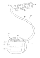
- FIG. 1 is a schematic view of one embodiment of an electrical stimulation system, according to the invention.
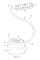
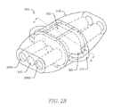
- FIGS. 2A and 2B illustrate a lead anchor that may be used to secure leads in the implantable electrical stimulation system of FIG. 1 , according to the invention
- FIG. 3A is an exploded pictorial view of the components of a lead anchor according to the invention.
- FIGS. 3B and 3C are front views of components of a lead anchor according to the invention.
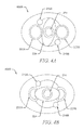
- FIGS. 4A , 4 B, and 4 C are cross-sectional views taken on plane A-A′ of FIG. 2B of the lead anchor in unlocked, intermediate, and locked configurations, respectively; according to the invention.
- FIG. 5 illustrates a method of using the lead anchor employing a tool, according to the invention.
- the present invention is directed to the area of lead anchors used with elongate implantable devices such as spinal cord leads, cardiac pacing leads or catheters, implantable devices or systems containing the lead anchors, methods of use and manufacture of lead anchors and implantable devices.
- the present invention is directed to an anchor employing a swivel anchor to secure stimulation leads, and methods of use and manufacture of the lead anchor.
- a lead as used herein is a cable including at least one electrical conductor for connecting one or more electrodes disposed on a distal end of the cable, and one or more terminals disposed on one or more proximal ends of the cable.
- Leads include, for example, percutaneous leads, paddle leads, and cuff leads.
- Examples of electrical stimulation systems with leads are present in, for example, U.S. Pat. Nos. 6,181,969; 6,516,227; 6,609,029; 6,609,032; 6,741,892; 7,244,150; 7,672,734; 7,761,165; 7,949,395; 7,974,706; 8,175,710; and 8,364,278, and U.S. Patent Application Publication Serial No. 2007/0150036, all of which are incorporated herein by reference.
- FIG. 1 is a schematic view of one embodiment of an electrical stimulation system 100 .
- the electrical stimulation system 100 includes a control module (e.g., a stimulator or pulse generator) 102 , a paddle body 104 , and at least one lead 106 , having a proximal end 105 and a distal end 107 , coupling the control module 102 to the paddle body 104 .
- the distal end 107 of the lead 106 may include an array of electrodes 134 disposed on the paddle body 104 .
- the control module 102 typically includes an electronic subassembly 110 and an optional power source 120 disposed in a sealed housing 114 .
- the control module 102 typically includes a connector 144 into which the proximal end 105 of the one or more leads 106 can be plugged to make an electrical connection via connector contacts on the control module 102 and terminals (not shown) on each of the one or more leads 106 .
- the electrical stimulation system 100 may include more, fewer, or different components and can have a variety of different configurations including those configurations disclosed in the electrical stimulation system references cited herein.
- the electrodes 134 can be disposed in an array at or near the distal end 107 of the lead 106 forming a percutaneous or isodiametric lead (not shown).
- the electrical stimulation system 100 or components of the electrical stimulation system are typically implanted into the body of a patient.
- the electrical stimulation system 100 can be used for a variety of applications including, but not limited to, brain stimulation, neural stimulation, spinal cord stimulation, muscle stimulation, and the like.
- the electrodes 134 can be formed using any conductive, biocompatible material. Examples of suitable materials include metals, alloys, conductive polymers, conductive carbon, and the like, as well as combinations thereof.
- the number of electrodes 134 in the array of electrodes 134 may vary. For example, there can be two, four, six, eight, ten, twelve, fourteen, sixteen, or more electrodes 134 . As will be recognized, other numbers of electrodes 134 may also be used.
- the electrodes of the paddle body 104 or one or more leads 106 are typically disposed in, or separated by, a non-conductive, biocompatible material including, for example, silicone, polyurethane, polyetheretherketone, epoxy, and the like, or combinations thereof.
- the paddle body 104 and one or more leads 106 may be formed in the desired shape by any suitable process including, for example, molding (including, injection molding), casting, and the like. Electrodes and connecting wires can be disposed onto or within a paddle body either prior to or subsequent to a molding or casting process.
- the non-conductive material typically extends from the distal end of the lead to the proximal end of each of the one or more leads 106 .
- the paddle body 104 and the one or more leads 106 may be a unitary structure or can be formed as separate structures, which may be permanently or detachably coupled.
- a lead anchor can be used in an implantable device, such as an implantable spinal cord stimulator, to anchor a lead connecting a control module to an electrode array.
- the lead anchor includes a fastener, which may be tightened to hold the lead.
- the lead anchor applies compression to the lead to hold the lead in place.
- FIG. 2A is a schematic view of a portion of one embodiment of a lead anchor 200 .
- Lead anchor 200 can be used to secure at least one lead 106 ( FIG. 1 ) within a patient body.
- the lead anchor 200 may be employed to secure at least two leads (or two separate elongated portions of a lead) which may provide an effective stimulation for at least two different target sites (not shown). Still further, securing the leads may reduce or avoid dislocation of the lead or leads from the target site.
- the lead anchor 200 includes an anchor housing 202 having a proximal portion 204 and a distal portion 206 .
- the anchor housing 202 may be employed to secure at least one lead 106 ( FIG. 1 ) of the electrical stimulation system 100 .
- the proximal portion 204 includes a first opening 208 A, a second opening 208 B, and a central opening 210 , such that the central opening 210 may be positioned in between the other two openings 208 A, 208 B.
- openings 208 A, 208 B, and 210 may be parallel, however, other arrangements such as triangular, irregular, or other configurations known to those skilled in the art may also be contemplated.
- the first opening 208 A and the second opening 208 B provide an entrance to sleeves 207 A, 207 B which define channels 212 A, 212 B which pass through the anchor housing 202 .
- the sleeves 207 A, 207 B are arranged to each receive a lead.
- Leads 106 ( FIG. 1 ) may pass through the channels 212 A, 212 B and thus across the anchor housing 202 .
- the central opening 210 includes a fitting, such as hex fitting 214 , adapted to accept a tool that is used to actuate the locking mechanism of the lead anchor 200 .
- Other configurations known to those skilled in the art, such as a slot or Phillips fitting, can be employed.
- one or more of the channels 212 A, 212 B may include a bend to provide a tapered form, which may facilitate insertion of the leads 106 ( FIG. 1 ) within the anchor housing 202 .
- the channels 212 A, 212 B may be formed in any other suitable configurations such as, but not limited to, straight or irregular configurations.
- the anchor housing 202 may also include one or more locking members 216 , such as pins, described in more detail below.
- the anchor housing 202 may be made of a metal, such as titanium, nickel, aluminum, stainless steel, copper, gold, silver, platinum and alloys thereof or any other biocompatible metal, or a rigid plastic or polymer material.
- the sleeves 207 A, 207 B may be made of any flexible, biocompatible material including, but not limited to, plastics or other polymer materials.
- FIG. 2B is schematic view of the lead anchor 200 with the anchor housing 202 be encapsulated in an overmold 218 .
- the overmold 218 may include a case, cover, sheath, or any other suitable structure.
- the overmold 218 may be formed of any biocompatible material such as plastics and polymers including, but not limited to, silicone, polyvinyl chloride, fluoropolymers, polyurethane, polycarbonate, acrylic compounds, thermoplastic polyesters, polypropylene, low-density polyethylenes, and other thermoplastic elastomers.
- the overmold 218 is made of silicone.
- Overmold 218 may provide strain relief to the leads 106 (FIG. a), and it also may safeguard the anchor housing 202 from an applied external force.
- the overmold 218 may include one or more suture structures 219 , such as suture tabs with openings 220 , to facilitate suturing the lead anchor 200 to patient tissue.
- FIG. 3A is an exploded pictorial view of components of one embodiment of the lead anchor 200 .
- Anchor housing 202 includes endplates 222 A, 222 B, a swivel anchor 224 , locking members 216 A, 216 B, and core housing 228 .
- the locking members 216 A, 216 B may include, for example, members such as pins, dowels, screws, bolts, or the like or any other suitable component.
- the materials employed for manufacturing the components of the anchor housing 202 may include, but are not limited to, stainless steel, titanium, cobalt-nickel alloy, other metals and alloys, rigid plastics, or other suitable biocompatible materials.
- Endplates 222 A, 222 B define the ends of anchor housing 202 .
- each endplate is generally rectangular with rounded ends although other suitable shapes can be used.
- each endplate 222 (either endplate 22 A or endplate 22 B of FIG. 3A ) includes two openings 208 A, 208 B formed lying on either side of a central opening 210 .
- the three openings 208 A, 208 B, 210 may lie generally on the vertical centerline of the element, with central opening 210 horizontally centered as well.
- Apertures 221 , 223 are formed above and below the openings 208 A, 208 B, 210 , and these apertures may be sized to accommodate locking members 216 A, 216 B.
- Core housing 228 forms the center of anchor housing 202 and provides a support structure for other components in a sandwich-shaped configuration, with endplates 222 A, 222 B lying on either side of the core housing 228 .
- Core housing 228 defines a cavity 230 to accommodate the swivel anchor 224 and locking members 216 A, 216 B, as discussed in detail below.
- the configuration of core housing 228 and cavity 230 are influenced by these elements.
- Swivel anchor 224 locks leads 106 ( FIG. 1 ) in place within core housing 228 .
- the swivel anchor 224 includes a solid, paddle-shaped locking portion 225 , with one or two tubular portions 227 A, 227 B extending longitudinally from the same.
- locking portion 225 presents a generally flattened form with curved surfaces (e.g., a form with an oval-shaped transverse cross-section) extending transversely within core housing 228 .
- the ends of locking portion 225 may form narrowed, rounded features.
- Tubular portions 227 A, 227 B extend longitudinally from the sides of the locking portion 225 , generally on the locking portion's axis of rotation.
- the tubular portion 227 A includes a fitting 214 suitable to receive a tool, such as a hex tool or a slotted or Phillips tool.
- a suitable tool such as a hex tool or a slotted or Phillips tool.
- the fitting 214 may receive a tip of a torque wrench which can then be used to rotate the swivel anchor to lock one or more leads in place.
- core housing 228 can be understood in relation to the components assembled within that element. As shown in FIG. 3B , core housing 228 defines a complex inner cavity 230 . That cavity results from a combination of a number of individual, simpler openings.
- a central bore 232 lies on the central axis of core housing 228 and is generally circular with a diameter sufficient to accommodate the locking portion 225 of the swivel anchor 224 . Overlapping the central bore are two lead bores 234 A, 234 B lying on the vertical centerline of core housing 228 and sized to receive a portion of each sleeves 207 A, 207 B, respectively (see FIG. 2A ).
- Locking member bores 236 A, 236 B also overlap central bore 232 and are located generally clockwise around the circumference of central bore 232 from the lead bores 234 A, 234 B. These bores are sized to accept a portion of each locking member 216 A, 216 B, respectively.
- FIG. 3A may be assembled by fitting an end plate 222 A over the central cavity 230 and inserting the swivel anchor 224 , sliding the tubular portion 227 A into the central opening 210 .
- the other end plate 222 B is then attached and the locking members 216 A, 216 B are inserted.
- the swivel anchor 224 have any other suitable shape, which may include an elliptical shape, an oval shape, or the like.
- the manufacturing of the anchor housing 202 may include machining processes such as, but not limited to, lathing, milling, drilling, cutting, and so forth.
- components of the anchor housing 202 may be manufactured by stamping, laser cutting, wire electromachining, sintering, or any other suitable mechanical process or combinations thereof.
- FIG. 3A Components illustrated in FIG. 3A may be combined in a number of configurations to obtain a functioning anchor housing 202 .
- one end plate 222 B and core housing 228 may be formed as a single unit.
- locking members 216 A, 216 B may be formed with the core housing 228 as a single unit.
- FIGS. 4A , 4 B, and 4 C are cross-sectional views of the lead anchor 200 in unlocked, intermediate, and locked configurations, respectively.
- the swivel anchor 224 rests within the cavity 230 .
- the swivel anchor 224 can rotate within central cavity 230 without necessarily bearing on the leads 106 or sleeves 207 A, 207 B.
- leads 106 may move freely within the sleeves 207 A, 207 B, which are not compressed by the swivel anchor 224 .
- the lead anchor 200 assumes an intermediate configuration 400 B of FIG.
- the swivel anchor 224 is urged against the locking members 216 A, 216 B by the sleeves 207 A, 207 B and the leads 106 residing in the sleeves.
- the swivel anchor 224 is thus locked in a stable configuration 400 C, which secures the leads 106 within the sleeves 207 A, 207 B.
- the leads are then anchored in position within the patient.
- FIG. 5 is a perspective view illustrating the lead anchor 200 being engaged by a tool 502 .
- Leads 106 (not shown) may be inserted through the lead anchor 200 .
- a tool 502 is employed to secure the leads 106 .
- the tool 502 may be, for example, a torque wrench 502 or other suitable tool adapted to engage the fitting 214 .
- the lead anchor 200 of FIG. 2B may receive a pair of leads 106 (not shown). Initially, leads 106 are placed in position to achieve the desired paresthesia at the chosen site of stimulation. In at least some embodiments, the leads are inserted into the sleeves 207 A, 207 B and carried in the channels 212 A, 212 B of the anchor housing 202 . The lead anchor 200 is slid along the length of the leads until it is in the desired position for anchoring to the ligament or fascia. After the leads have been positioned, the tool 502 engages the fitting 214 of the lead anchor 202 . The distal end of the tool 502 includes a head 504 shaped to engage the fitting 214 ( FIG. 4C ).
- the user inserts the distal end of the tool 502 into the central opening 210 to engage the fitting 214 (not shown) of swivel anchor 224 . Further, the user provides sufficient torque at the proximal end of the torque wrench 502 to rotate the swivel anchor 224 (see FIGS. 4A-C ). The rotation of swivel anchor 224 moves the swivel anchor to the intermediate configuration 400 B, which may provide for the maximum compression to leads 106 . Continued rotation moves the swivel anchor 224 to the stable locked configuration 400 C with the swivel anchor 224 abutting both the sleeves 207 A, 207 B and the locking members 216 A, 216 B, thus securing the leads 106 within the lead anchor 200 . In at least some embodiments, the user may rotate the fitting 214 in the opposite direction to cause the swivel anchor 224 to move to the unlocked configuration 400 A, thereby freeing the leads 106 .
- Embodiments of the present disclosure may be used in any medical or non-medical procedure, including any medical procedure where one or more body part receive electrical stimulation.
- at least certain aspects of the aforementioned embodiments may be combined with other aspects of the embodiments, or removed.
Landscapes
- Health & Medical Sciences (AREA)
- Nuclear Medicine, Radiotherapy & Molecular Imaging (AREA)
- Animal Behavior & Ethology (AREA)
- Veterinary Medicine (AREA)
- Cardiology (AREA)
- Heart & Thoracic Surgery (AREA)
- Engineering & Computer Science (AREA)
- Public Health (AREA)
- Radiology & Medical Imaging (AREA)
- Biomedical Technology (AREA)
- Life Sciences & Earth Sciences (AREA)
- General Health & Medical Sciences (AREA)
- Neurology (AREA)
- Neurosurgery (AREA)
- Orthopedic Medicine & Surgery (AREA)
- Electrotherapy Devices (AREA)
Abstract
Description
- This application claims the benefit under 35 U.S.C. §119(e) of U.S. Provisional Patent Application Ser. No. 61/670,337 filed on Jul. 11, 2012, which is incorporated herein by reference.
- The present invention is directed to the area of implantable stimulation systems and lead anchors for the implantable stimulation systems. The present invention is also directed to the method of manufacture and use of the implantable stimulation systems and the lead anchors.
- Implantable stimulation systems have proven therapeutic in a variety of diseases and disorders. For example, spinal cord stimulation systems may be implanted in the spinal cord to treat chronic pain syndromes, and in the brain to treat refractory chronic pain syndromes, movement disorders, and epilepsy. Peripheral nerve stimulation systems may be used to treat chronic pain syndrome and incontinence. In some cases, paralyzed extremities in spinal cord injury patients may be treated using functional electrical stimulation. Moreover, electrical stimulation systems can be implanted subcutaneously to stimulate subcutaneous tissue, including subcutaneous nerves, such as the occipital nerve.
- In general, a stimulator includes a control module (with a pulse generator), a lead, and an array of stimulator electrodes. The stimulator electrodes are placed in contact with or near the nerves, muscles, or other tissue to be stimulated. The pulse generator in the control module generates electrical pulses that are delivered through the electrodes to body tissue. The lead is often anchored at one or more places to prevent or reduce the movement of the lead or stimulator electrodes which could damage tissue, move the stimulator electrodes out of the desired position, or interrupt the connection between the stimulator electrodes and the control module.
- Conventionally known lead anchors have shown inadequate lead retention strength and thus result into lead migration, which may further include chances of lead breakage or loose connection. In addition, many conventional anchors provide anchorage to a single lead and thus employment of multiple lead anchors increases overall volume of the implantable stimulation system.
- Therefore, there exists a need for a robust lead anchor to secure leads efficiently during stimulation procedures.
- One embodiment is a lead anchor including a core housing defining a cavity having a periphery; a swivel anchor disposed in the cavity and having a tubular portion and a locking portion with opposing ends; at least two locking members with at least a portion of each of the locking members disposed within the cavity at the periphery of the cavity; and at least two sleeves with at least a portion of each of the sleeves disposed within the cavity at the periphery of the cavity. The tubular portion is adapted to receive an external tool. The swivel anchor is configured and arranged to rotate within the cavity using the external tool. The lead anchor is configured and arranged to have at least an unlocked configuration, in which the swivel anchor can rotate within the cavity of the core housing without necessarily compressing the sleeves, and a locked configuration, in which the opposing ends of the locking portion of the swivel anchor each lie between one of the sleeves and one of the locking members and compress the sleeves and any lead disposed within the sleeves to hold that lead in place.
- Another embodiment is a system including the lead anchor described above and at least one lead configured and arranged for a portion of the at least one lead to be received within at least one of the sleeves of the lead anchor.
- Yet another embodiment is a method of implanting an electrical stimulation device. The method including implanting at least one lead near tissue to be stimulated and disposing a lead anchor around a portion of the at least one lead. The lead anchor includes a core housing defining a cavity having a periphery; a swivel anchor disposed in the cavity and having a tubular portion and a locking portion with opposing ends where the tubular portion is adapted to receive an external tool and the swivel anchor is configured and arranged to rotate within the cavity using the external tool; at least two locking members with at least a portion of each of the locking members is disposed within the cavity at the periphery of the cavity; and at least two sleeves carried within the channels with at least a portion of each of the sleeves is disposed within the cavity at the periphery of the cavity. As the lead anchor is disposed around the portion of the lead one lead, the swivel anchor is disposed in an unlocked position. The method also includes rotating the swivel anchor to a locked position in which the opposing ends of the locking portion of the swivel anchor each lie between one of the sleeves and one of the locking members and compress the sleeves and the at least one lead disposed within the sleeves to hold the at least one lead in place of the lead anchor.
- Non-limiting and non-exhaustive embodiments of the present disclosure are described with reference to the following drawings. In the drawings, like reference numerals refer to like parts throughout the various figures unless otherwise specified.
- For a better understanding of the present disclosure, reference will be made to the following detailed description, which is to be ready in association with the accompanying drawings, wherein:
-
FIG. 1 is a schematic view of one embodiment of an electrical stimulation system, according to the invention; -
FIGS. 2A and 2B illustrate a lead anchor that may be used to secure leads in the implantable electrical stimulation system ofFIG. 1 , according to the invention; -
FIG. 3A is an exploded pictorial view of the components of a lead anchor according to the invention; -
FIGS. 3B and 3C are front views of components of a lead anchor according to the invention; -
FIGS. 4A , 4B, and 4C are cross-sectional views taken on plane A-A′ ofFIG. 2B of the lead anchor in unlocked, intermediate, and locked configurations, respectively; according to the invention; and -
FIG. 5 illustrates a method of using the lead anchor employing a tool, according to the invention. - Corresponding reference characters indicate corresponding components throughout the several views of the drawings.
- The present invention is directed to the area of lead anchors used with elongate implantable devices such as spinal cord leads, cardiac pacing leads or catheters, implantable devices or systems containing the lead anchors, methods of use and manufacture of lead anchors and implantable devices. In addition, the present invention is directed to an anchor employing a swivel anchor to secure stimulation leads, and methods of use and manufacture of the lead anchor.
- A lead as used herein is a cable including at least one electrical conductor for connecting one or more electrodes disposed on a distal end of the cable, and one or more terminals disposed on one or more proximal ends of the cable. Leads include, for example, percutaneous leads, paddle leads, and cuff leads. Examples of electrical stimulation systems with leads are present in, for example, U.S. Pat. Nos. 6,181,969; 6,516,227; 6,609,029; 6,609,032; 6,741,892; 7,244,150; 7,672,734; 7,761,165; 7,949,395; 7,974,706; 8,175,710; and 8,364,278, and U.S. Patent Application Publication Serial No. 2007/0150036, all of which are incorporated herein by reference.
- In the following sections, embodiments of the present disclosure will be described with reference to a procedure to secure a spinal cord stimulation (SCS) lead with an anchor assembly. It will be understood that this choice is merely exemplary and that the device may be utilized in any other organ, such as deep brain stimulation (DBS), peripheral nerve stimulation (PNS) or any other stimulation that requires securing the leads with the anchor assembly.
-
FIG. 1 is a schematic view of one embodiment of anelectrical stimulation system 100. Theelectrical stimulation system 100 includes a control module (e.g., a stimulator or pulse generator) 102, apaddle body 104, and at least onelead 106, having aproximal end 105 and adistal end 107, coupling thecontrol module 102 to thepaddle body 104. Thedistal end 107 of thelead 106 may include an array ofelectrodes 134 disposed on thepaddle body 104. Thecontrol module 102 typically includes anelectronic subassembly 110 and anoptional power source 120 disposed in a sealedhousing 114. Thecontrol module 102 typically includes aconnector 144 into which theproximal end 105 of the one ormore leads 106 can be plugged to make an electrical connection via connector contacts on thecontrol module 102 and terminals (not shown) on each of the one ormore leads 106. It should be understood that theelectrical stimulation system 100 may include more, fewer, or different components and can have a variety of different configurations including those configurations disclosed in the electrical stimulation system references cited herein. For example, instead of apaddle body 104, theelectrodes 134 can be disposed in an array at or near thedistal end 107 of thelead 106 forming a percutaneous or isodiametric lead (not shown). - The
electrical stimulation system 100 or components of the electrical stimulation system, including one or more of theleads 106, thepaddle body 104, and thecontrol module 102, are typically implanted into the body of a patient. Theelectrical stimulation system 100 can be used for a variety of applications including, but not limited to, brain stimulation, neural stimulation, spinal cord stimulation, muscle stimulation, and the like. - The
electrodes 134 can be formed using any conductive, biocompatible material. Examples of suitable materials include metals, alloys, conductive polymers, conductive carbon, and the like, as well as combinations thereof. The number ofelectrodes 134 in the array ofelectrodes 134 may vary. For example, there can be two, four, six, eight, ten, twelve, fourteen, sixteen, ormore electrodes 134. As will be recognized, other numbers ofelectrodes 134 may also be used. - The electrodes of the
paddle body 104 or one or more leads 106 are typically disposed in, or separated by, a non-conductive, biocompatible material including, for example, silicone, polyurethane, polyetheretherketone, epoxy, and the like, or combinations thereof. Thepaddle body 104 and one or more leads 106 may be formed in the desired shape by any suitable process including, for example, molding (including, injection molding), casting, and the like. Electrodes and connecting wires can be disposed onto or within a paddle body either prior to or subsequent to a molding or casting process. The non-conductive material typically extends from the distal end of the lead to the proximal end of each of the one or more leads 106. Thepaddle body 104 and the one or more leads 106 may be a unitary structure or can be formed as separate structures, which may be permanently or detachably coupled. - A lead anchor can be used in an implantable device, such as an implantable spinal cord stimulator, to anchor a lead connecting a control module to an electrode array. The lead anchor includes a fastener, which may be tightened to hold the lead. In at least some embodiments, the lead anchor applies compression to the lead to hold the lead in place.
-
FIG. 2A is a schematic view of a portion of one embodiment of alead anchor 200.Lead anchor 200 can be used to secure at least one lead 106 (FIG. 1 ) within a patient body. In at least some embodiments, thelead anchor 200 may be employed to secure at least two leads (or two separate elongated portions of a lead) which may provide an effective stimulation for at least two different target sites (not shown). Still further, securing the leads may reduce or avoid dislocation of the lead or leads from the target site. - The
lead anchor 200 includes ananchor housing 202 having aproximal portion 204 and adistal portion 206. In one embodiment, theanchor housing 202 may be employed to secure at least one lead 106 (FIG. 1 ) of theelectrical stimulation system 100. Theproximal portion 204 includes afirst opening 208A, asecond opening 208B, and acentral opening 210, such that thecentral opening 210 may be positioned in between the other twoopenings openings - The
first opening 208A and thesecond opening 208B provide an entrance tosleeves channels anchor housing 202. Thesleeves FIG. 1 ) may pass through thechannels anchor housing 202. Thecentral opening 210 includes a fitting, such ashex fitting 214, adapted to accept a tool that is used to actuate the locking mechanism of thelead anchor 200. Other configurations known to those skilled in the art, such as a slot or Phillips fitting, can be employed. In at least one embodiment, one or more of thechannels FIG. 1 ) within theanchor housing 202. Alternatively, thechannels anchor housing 202 may also include one ormore locking members 216, such as pins, described in more detail below. Theanchor housing 202 may be made of a metal, such as titanium, nickel, aluminum, stainless steel, copper, gold, silver, platinum and alloys thereof or any other biocompatible metal, or a rigid plastic or polymer material. Thesleeves -
FIG. 2B is schematic view of thelead anchor 200 with theanchor housing 202 be encapsulated in anovermold 218. Theovermold 218 may include a case, cover, sheath, or any other suitable structure. In one embodiment, theovermold 218 may be formed of any biocompatible material such as plastics and polymers including, but not limited to, silicone, polyvinyl chloride, fluoropolymers, polyurethane, polycarbonate, acrylic compounds, thermoplastic polyesters, polypropylene, low-density polyethylenes, and other thermoplastic elastomers. In some embodiments, theovermold 218 is made of silicone. -
Overmold 218 may provide strain relief to the leads 106 (FIG. a), and it also may safeguard theanchor housing 202 from an applied external force. Theovermold 218 may include one ormore suture structures 219, such as suture tabs withopenings 220, to facilitate suturing thelead anchor 200 to patient tissue. -
FIG. 3A is an exploded pictorial view of components of one embodiment of thelead anchor 200.Anchor housing 202 includesendplates 222A, 222B, aswivel anchor 224, lockingmembers core housing 228. The lockingmembers anchor housing 202 may include, but are not limited to, stainless steel, titanium, cobalt-nickel alloy, other metals and alloys, rigid plastics, or other suitable biocompatible materials. -
Endplates 222A, 222B define the ends ofanchor housing 202. In the illustrated embodiment, each endplate is generally rectangular with rounded ends although other suitable shapes can be used. As seen more clearly inFIG. 3C , each endplate 222 (either endplate 22A or endplate 22B ofFIG. 3A ) includes twoopenings central opening 210. The threeopenings central opening 210 horizontally centered as well.Apertures openings members -
Core housing 228 forms the center ofanchor housing 202 and provides a support structure for other components in a sandwich-shaped configuration, withendplates 222A, 222B lying on either side of thecore housing 228.Core housing 228 defines acavity 230 to accommodate theswivel anchor 224 and lockingmembers core housing 228 andcavity 230 are influenced by these elements. -
Swivel anchor 224 locks leads 106 (FIG. 1 ) in place withincore housing 228. Theswivel anchor 224 includes a solid, paddle-shapedlocking portion 225, with one or twotubular portions portion 225 presents a generally flattened form with curved surfaces (e.g., a form with an oval-shaped transverse cross-section) extending transversely withincore housing 228. The ends of lockingportion 225 may form narrowed, rounded features.Tubular portions portion 225, generally on the locking portion's axis of rotation. - In one embodiment, the
tubular portion 227A includes a fitting 214 suitable to receive a tool, such as a hex tool or a slotted or Phillips tool. With fitting 214, an operator can use a suitable tool to turn theswivel anchor 224 withincore housing 228. For example, the fitting 214 may receive a tip of a torque wrench which can then be used to rotate the swivel anchor to lock one or more leads in place. - The configuration of
core housing 228 can be understood in relation to the components assembled within that element. As shown inFIG. 3B ,core housing 228 defines a complexinner cavity 230. That cavity results from a combination of a number of individual, simpler openings. Acentral bore 232 lies on the central axis ofcore housing 228 and is generally circular with a diameter sufficient to accommodate the lockingportion 225 of theswivel anchor 224. Overlapping the central bore are twolead bores 234A, 234B lying on the vertical centerline ofcore housing 228 and sized to receive a portion of eachsleeves FIG. 2A ). Locking member bores 236A, 236B also overlapcentral bore 232 and are located generally clockwise around the circumference ofcentral bore 232 from the lead bores 234A, 234B. These bores are sized to accept a portion of each lockingmember - The components shown in
FIG. 3A may be assembled by fitting anend plate 222A over thecentral cavity 230 and inserting theswivel anchor 224, sliding thetubular portion 227A into thecentral opening 210. The other end plate 222B is then attached and thelocking members - Alternatively, the
swivel anchor 224 have any other suitable shape, which may include an elliptical shape, an oval shape, or the like. The manufacturing of theanchor housing 202 may include machining processes such as, but not limited to, lathing, milling, drilling, cutting, and so forth. In at least some embodiments, components of theanchor housing 202 may be manufactured by stamping, laser cutting, wire electromachining, sintering, or any other suitable mechanical process or combinations thereof. - Components illustrated in
FIG. 3A may be combined in a number of configurations to obtain afunctioning anchor housing 202. For instance, in an exemplary embodiment, one end plate 222B andcore housing 228 may be formed as a single unit. In yet another embodiment, lockingmembers core housing 228 as a single unit. -
FIGS. 4A , 4B, and 4C are cross-sectional views of thelead anchor 200 in unlocked, intermediate, and locked configurations, respectively. In theunlocked configuration 400A, theswivel anchor 224 rests within thecavity 230. In thisunlocked configuration 400A ofFIG. 4A , theswivel anchor 224 can rotate withincentral cavity 230 without necessarily bearing on theleads 106 orsleeves sleeves swivel anchor 224. Upon rotation of the swivel anchor 224 (in a clockwise direction for the illustrated embodiment), thelead anchor 200 assumes an intermediate configuration 400B ofFIG. 4B where theswivel anchor 224 compresses thesleeves leads 106 disposed in the sleeves. This intermediate configuration 400B lies in an unstable equilibrium. Further rotation of theswivel anchor 224 results in the stable lockedconfiguration 400C ofFIG. 4C . Prior to reaching the intermediate configuration 400B, theswivel anchor 224 will rotate toward the unlocked position. Once theswivel anchor 224 passes the point of maximum compression ofsleeves swivel anchor 224 with rotate toward the stable lockedconfiguration 400C. In the lockedconfiguration 400C, theswivel anchor 224 is urged against the lockingmembers sleeves leads 106 residing in the sleeves. Theswivel anchor 224 is thus locked in astable configuration 400C, which secures theleads 106 within thesleeves lead anchor 200 is then attached to patient tissue, the leads are then anchored in position within the patient. -
FIG. 5 is a perspective view illustrating thelead anchor 200 being engaged by atool 502. Leads 106 (not shown) may be inserted through thelead anchor 200. In one embodiment, atool 502 is employed to secure the leads 106. Thetool 502 may be, for example, atorque wrench 502 or other suitable tool adapted to engage the fitting 214. - The
lead anchor 200 ofFIG. 2B may receive a pair of leads 106 (not shown). Initially, leads 106 are placed in position to achieve the desired paresthesia at the chosen site of stimulation. In at least some embodiments, the leads are inserted into thesleeves channels anchor housing 202. Thelead anchor 200 is slid along the length of the leads until it is in the desired position for anchoring to the ligament or fascia. After the leads have been positioned, thetool 502 engages the fitting 214 of thelead anchor 202. The distal end of thetool 502 includes ahead 504 shaped to engage the fitting 214 (FIG. 4C ). The user inserts the distal end of thetool 502 into thecentral opening 210 to engage the fitting 214 (not shown) ofswivel anchor 224. Further, the user provides sufficient torque at the proximal end of thetorque wrench 502 to rotate the swivel anchor 224 (seeFIGS. 4A-C ). The rotation ofswivel anchor 224 moves the swivel anchor to the intermediate configuration 400B, which may provide for the maximum compression to leads 106. Continued rotation moves theswivel anchor 224 to the stable lockedconfiguration 400C with theswivel anchor 224 abutting both thesleeves locking members leads 106 within thelead anchor 200. In at least some embodiments, the user may rotate the fitting 214 in the opposite direction to cause theswivel anchor 224 to move to theunlocked configuration 400A, thereby freeing theleads 106. - Embodiments of the present disclosure may be used in any medical or non-medical procedure, including any medical procedure where one or more body part receive electrical stimulation. In addition, at least certain aspects of the aforementioned embodiments may be combined with other aspects of the embodiments, or removed.
- While the present disclosure has been described by means of specific embodiments and applications thereof, numerous modifications and variations could be made thereto by those skilled in the art without departing from the scope of the present disclosure set forth in the claims.
Claims (20)
Priority Applications (1)
| Application Number | Priority Date | Filing Date | Title |
|---|---|---|---|
| US13/937,937 US8892216B2 (en) | 2012-07-11 | 2013-07-09 | Lead anchor and related methods of use |
Applications Claiming Priority (2)
| Application Number | Priority Date | Filing Date | Title |
|---|---|---|---|
| US201261670337P | 2012-07-11 | 2012-07-11 | |
| US13/937,937 US8892216B2 (en) | 2012-07-11 | 2013-07-09 | Lead anchor and related methods of use |
Publications (2)
| Publication Number | Publication Date |
|---|---|
| US20140018884A1 true US20140018884A1 (en) | 2014-01-16 |
| US8892216B2 US8892216B2 (en) | 2014-11-18 |
Family
ID=49914637
Family Applications (1)
| Application Number | Title | Priority Date | Filing Date |
|---|---|---|---|
| US13/937,937 Expired - Fee Related US8892216B2 (en) | 2012-07-11 | 2013-07-09 | Lead anchor and related methods of use |
Country Status (1)
| Country | Link |
|---|---|
| US (1) | US8892216B2 (en) |
Cited By (5)
| Publication number | Priority date | Publication date | Assignee | Title |
|---|---|---|---|---|
| US20140148753A1 (en) * | 2012-11-26 | 2014-05-29 | Boston Scientific Neuromodulation Corporation | Systems and methods for making and using an electrical stimulation system with photonic stimulation capabilities |
| US20140343646A1 (en) * | 2013-05-15 | 2014-11-20 | Boston Scientific Neuromodulation Corporation | Dual side load anchor for electrode lead, systems containing the anchor, and methods of making and using |
| EP3421079A1 (en) * | 2017-06-30 | 2019-01-02 | GTX medical B.V. | A lead for neuromodulation |
| US11324944B1 (en) * | 2019-07-23 | 2022-05-10 | Verily Life Sciences Llc | Flexible cable assembly for medical implantation |
| US20230116791A1 (en) * | 2020-05-01 | 2023-04-13 | Advanced Neuromodulation Systems, Inc. | Foraminal ligament anchor for application in drg therapy |
Families Citing this family (1)
| Publication number | Priority date | Publication date | Assignee | Title |
|---|---|---|---|---|
| US9302094B2 (en) | 2013-10-25 | 2016-04-05 | Boston Scientific Neuromodulation Corporation | Lead anchor with pivotable paddles and systems and methods using the lead anchor |
Citations (1)
| Publication number | Priority date | Publication date | Assignee | Title |
|---|---|---|---|---|
| US8140172B1 (en) * | 2008-07-11 | 2012-03-20 | Advanced Neuromodulation Systems, Inc. | Implantable anchor with locking arm |
Family Cites Families (13)
| Publication number | Priority date | Publication date | Assignee | Title |
|---|---|---|---|---|
| WO2000000251A1 (en) | 1998-06-26 | 2000-01-06 | Advanced Bionics Corporation | Programmable current output stimulus stage for implantable device |
| US6393325B1 (en) | 1999-01-07 | 2002-05-21 | Advanced Bionics Corporation | Directional programming for implantable electrode arrays |
| US6516227B1 (en) | 1999-07-27 | 2003-02-04 | Advanced Bionics Corporation | Rechargeable spinal cord stimulator system |
| US7949395B2 (en) | 1999-10-01 | 2011-05-24 | Boston Scientific Neuromodulation Corporation | Implantable microdevice with extended lead and remote electrode |
| US6609029B1 (en) | 2000-02-04 | 2003-08-19 | Advanced Bionics Corporation | Clip lock mechanism for retaining lead |
| US6741892B1 (en) | 2000-03-10 | 2004-05-25 | Advanced Bionics Corporation | Movable contact locking mechanism for spinal cord stimulator lead connector |
| US8364278B2 (en) | 2002-01-29 | 2013-01-29 | Boston Scientific Neuromodulation Corporation | Lead assembly for implantable microstimulator |
| US7761165B1 (en) | 2005-09-29 | 2010-07-20 | Boston Scientific Neuromodulation Corporation | Implantable stimulator with integrated plastic housing/metal contacts and manufacture and use |
| US8700178B2 (en) | 2005-12-27 | 2014-04-15 | Boston Scientific Neuromodulation Corporation | Stimulator leads and methods for lead fabrication |
| US7672734B2 (en) | 2005-12-27 | 2010-03-02 | Boston Scientific Neuromodulation Corporation | Non-linear electrode array |
| US7244150B1 (en) | 2006-01-09 | 2007-07-17 | Advanced Bionics Corporation | Connector and methods of fabrication |
| US8175710B2 (en) | 2006-03-14 | 2012-05-08 | Boston Scientific Neuromodulation Corporation | Stimulator system with electrode array and the method of making the same |
| US7974706B2 (en) | 2006-03-30 | 2011-07-05 | Boston Scientific Neuromodulation Corporation | Electrode contact configurations for cuff leads |
-
2013
- 2013-07-09 US US13/937,937 patent/US8892216B2/en not_active Expired - Fee Related
Patent Citations (1)
| Publication number | Priority date | Publication date | Assignee | Title |
|---|---|---|---|---|
| US8140172B1 (en) * | 2008-07-11 | 2012-03-20 | Advanced Neuromodulation Systems, Inc. | Implantable anchor with locking arm |
Cited By (7)
| Publication number | Priority date | Publication date | Assignee | Title |
|---|---|---|---|---|
| US20140148753A1 (en) * | 2012-11-26 | 2014-05-29 | Boston Scientific Neuromodulation Corporation | Systems and methods for making and using an electrical stimulation system with photonic stimulation capabilities |
| US9415154B2 (en) * | 2012-11-26 | 2016-08-16 | Boston Scientific Neuromodulation Corporation | Systems and methods for making and using an electrical stimulation system with photonic stimulation capabilities |
| US20140343646A1 (en) * | 2013-05-15 | 2014-11-20 | Boston Scientific Neuromodulation Corporation | Dual side load anchor for electrode lead, systems containing the anchor, and methods of making and using |
| EP3421079A1 (en) * | 2017-06-30 | 2019-01-02 | GTX medical B.V. | A lead for neuromodulation |
| US11324944B1 (en) * | 2019-07-23 | 2022-05-10 | Verily Life Sciences Llc | Flexible cable assembly for medical implantation |
| US20230116791A1 (en) * | 2020-05-01 | 2023-04-13 | Advanced Neuromodulation Systems, Inc. | Foraminal ligament anchor for application in drg therapy |
| US12226629B2 (en) * | 2020-05-01 | 2025-02-18 | Advanced Neuromodulation Systems, Inc. | Foraminal ligament anchor for application in DRG therapy |
Also Published As
| Publication number | Publication date |
|---|---|
| US8892216B2 (en) | 2014-11-18 |
Similar Documents
| Publication | Publication Date | Title |
|---|---|---|
| EP3458154B1 (en) | Connector assembly with contact rings comprising biased ball-spring contacts | |
| US9839787B2 (en) | Systems and methods for making and using connector contact arrays for electrical stimulation systems | |
| US10603499B2 (en) | Tapered implantable lead and connector interface and methods of making and using | |
| US10307602B2 (en) | Threaded connector assembly and methods of making and using the same | |
| EP2456518B1 (en) | Multi-port modular connector for implantable electrical stimulation systems and methods of making | |
| US10493269B2 (en) | Leads for electrostimulation of peripheral nerves and other targets | |
| US11951317B2 (en) | Biased lead connector for operating room cable assembly and methods of making and using | |
| EP2429632B1 (en) | Torque lock anchor and methods and devices using the anchor | |
| US9504839B2 (en) | Tension clamp side loading lead anchor and methods and systems using the lead anchor | |
| US9242074B2 (en) | Medical device anchor and method of manufacture thereof | |
| AU2018331512B2 (en) | Actuatable lead connector for an operating room cable assembly and methods of making and using | |
| US8301255B2 (en) | Retention assemblies for implantable electric stimulation systems and methods of making and using | |
| US9517334B2 (en) | Lead anchors and systems and methods employing the lead anchors | |
| US8892216B2 (en) | Lead anchor and related methods of use | |
| US20140343645A1 (en) | Electrical stimulation leads and systems with anchoring units and methods of making and using | |
| US10071242B2 (en) | Lead anchor for an electrical stimulation system | |
| US10232169B2 (en) | Burr hole plugs for electrical stimulation systems and methods of making and using | |
| CA2825356A1 (en) | Torque lock anchor and methods and devices using the anchor | |
| US20140343646A1 (en) | Dual side load anchor for electrode lead, systems containing the anchor, and methods of making and using | |
| EP4414023A2 (en) | Screwless implantable medical lead extension |
Legal Events
| Date | Code | Title | Description |
|---|---|---|---|
| AS | Assignment |
Owner name: BOSTON SCIENTIFIC NEUROMODULATION CORPORATION, CAL Free format text: ASSIGNMENT OF ASSIGNORS INTEREST;ASSIGNOR:LEVEN, JACOB B.;REEL/FRAME:030761/0654 Effective date: 20130603 |
|
| FEPP | Fee payment procedure |
Free format text: PAYOR NUMBER ASSIGNED (ORIGINAL EVENT CODE: ASPN); ENTITY STATUS OF PATENT OWNER: LARGE ENTITY |
|
| FEPP | Fee payment procedure |
Free format text: MAINTENANCE FEE REMINDER MAILED (ORIGINAL EVENT CODE: REM.) |
|
| LAPS | Lapse for failure to pay maintenance fees |
Free format text: PATENT EXPIRED FOR FAILURE TO PAY MAINTENANCE FEES (ORIGINAL EVENT CODE: EXP.); ENTITY STATUS OF PATENT OWNER: LARGE ENTITY |
|
| STCH | Information on status: patent discontinuation |
Free format text: PATENT EXPIRED DUE TO NONPAYMENT OF MAINTENANCE FEES UNDER 37 CFR 1.362 |
|
| FP | Lapsed due to failure to pay maintenance fee |
Effective date: 20181118 |