US201331A - Improvement in dust-conveyers for thrashing-machines - Google Patents
Improvement in dust-conveyers for thrashing-machines Download PDFInfo
- Publication number
- US201331A US201331A US201331DA US201331A US 201331 A US201331 A US 201331A US 201331D A US201331D A US 201331DA US 201331 A US201331 A US 201331A
- Authority
- US
- United States
- Prior art keywords
- dust
- thrashing
- machines
- cylinder
- case
- Prior art date
- Legal status (The legal status is an assumption and is not a legal conclusion. Google has not performed a legal analysis and makes no representation as to the accuracy of the status listed.)
- Expired - Lifetime
Links
- 239000000428 dust Substances 0.000 description 16
- 238000010276 construction Methods 0.000 description 4
- 238000004140 cleaning Methods 0.000 description 2
- 230000001105 regulatory Effects 0.000 description 2
Images
Classifications
-
- A—HUMAN NECESSITIES
- A01—AGRICULTURE; FORESTRY; ANIMAL HUSBANDRY; HUNTING; TRAPPING; FISHING
- A01F—PROCESSING OF HARVESTED PRODUCE; HAY OR STRAW PRESSES; DEVICES FOR STORING AGRICULTURAL OR HORTICULTURAL PRODUCE
- A01F12/00—Parts or details of threshing apparatus
- A01F12/54—Arrangements for collecting or removing dust
Definitions
- an aperture, 0, extending the entire length from side to side, or nearly the entire length.
- a removable sieve, F On top of the case 1, is secured a box, G, containing in the center a fan-case, H, with suction-fan I therein.
- the sides of the fan-case have suitable openings 1), as shown, and a discharge-spout, J, extends upward from said fan-case.
- a door, d hinged at the top, and of such dimensions that by opening said door the screen F can be pulled out when required.
- the screen F prevents-anythin g but the dust from passing upward.
Description
eeeeeeeeeeeee 1.
f E. S. GHURGHMAN. Dust-Conveyer for Thrashing-Machine.
No. 20l,33l. Patented March 19,1878.
F'xql.
2 Sheets-Sheet 2,, E. S. CHURGHMAN.
Dust-Conveyer for Thrashing-Machine- No; 201,331. Pat d March 19, 1878.
T'ugJL A. @iitmsms: 9.
MM. FMW igmr HANM gltitmmpa N- PETERS, PHOTOMTHOGRAPHER,WASHINGTON, D C.
UNITED STATES PATENT OFFICE.
EDWARD S. GHURCHMAN, OF PLAIN CITY, OHIO.
IMPROVEMENT IN DUST-CONVEYERS FOR THRASHlNG-MACHINES.
Specification formingpart of Letters Patent No. 201,331, dated March 19, 1878; application filed September 20, 1876.
To all whom it may concern:
Be it known that I, E. S. OHURcHuAN, 0 Plain City, in the county of Madison and State of Ohio, have invented certain new and useful Improvements in Thrashing-Machines; and I do hereby declare the following to be a full, clear, and exact description thereof, reference being had to the accompanying drawings, and to the letters of reference marked thereon.
The nature of my invention consists in the construction and arrangement of an attachment for thrashing-machines, having for its object to facilitate the working of the machine, and to separate and carry off the dust from the point where it first originates, as will be hereinafter more fully set forth.
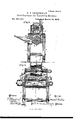
In order to enable others skilled in the art to which my invention appertains to make and use the same, I will now proceed to describe its construction and operation, referring to the annexed drawings, which form a part of this specification, and in which Figure l is a perspective View of a part of a thrashing-machine with my attachment applied thereto. Fig.2 is a transverse vertical section through the line :10 on of Fig. 3. Fig. 3 is a vertical section through the line 3 y of Fig. 2.
A represents part of the frame-work of a thrashing-machine, with feed-table or hopper B, and O is the thrashing-cylinder, constructed in any of the known and usual ways.
The cylinder 0 is inclosed at the top and sides by a case, D, and in the top of this case,
above the rear portion of the cylinder, is an aperture, 0, extending the entire length from side to side, or nearly the entire length. Over this aperture, on top of the case, is laid a removable sieve, F. On top of the case 1) is secured a box, G, containing in the center a fan-case, H, with suction-fan I therein. The sides of the fan-case have suitable openings 1), as shown, and a discharge-spout, J, extends upward from said fan-case. In the side of the box G is a door, d, hinged at the top, and of such dimensions that by opening said door the screen F can be pulled out when required.
When the thrashing-m achine is in operation, it will be seen that the fan I draws the dust from the cylinder 0 and feed-hopper B directly upward through the screen F into the box G, thence through the fan-case to and out through the discharge-spout.
It will thus be seen that the dust is taken from the inside of the cylinder-case D just at the point where it first originates, the fan drawing it through said cylinder cap or case directly in the rear of the cylinder, and in doing so it increases the draft of the machine, thereby making it take the grain more easily.
This attachment not only protects the feeder from dust, but also from flying grain and sticks from the cylinder. It makes the machine feed easier and more regularly, and takes all the dust away from the machine.
The screen F prevents-anythin g but the dust from passing upward.
The draft can easily be regulated by opening the door d more or less; and the screen may be removed from the box G through said door, when necessary, for cleaning the same, or for other purposes.
This attachment is applicable to any thrashing-machine.
I am well aware that suction-fans and dustconveyers have been arranged, in combination withthrashing-machines,in various ways; and I do, therefore, not claim such, broadly, as my invention. I take the dust from the'inside of the cylinder-cap directly over the rear .portion of the cylinder, so as to commence the suction, as it were, just at the point where the dust originates.
Having thus fully described my invention, what I claim as new, and desire to secure by Letters Patent, is
In a thrashing-machine, the combination, with the feed-hopper B and cylinder 0, of the cap D, having aperture a, the removable screen F, box G, with hinged side door 01, and the fan-case H, with fan I and discharge-spout J, all constructed and arranged to operate sub stantially as and for the purposes herein set forth.
In testimony that I claim the foregoing as my own I affix my signature in presence of two witnesses.
EDWARD S. GHURCHMAN.
I WVitnesses:
J. S. BRITTON, HENRY W. Bowsnn.
Publications (1)
| Publication Number | Publication Date |
|---|---|
| US201331A true US201331A (en) | 1878-03-19 |
Family
ID=2270736
Family Applications (1)
| Application Number | Title | Priority Date | Filing Date |
|---|---|---|---|
| US201331D Expired - Lifetime US201331A (en) | Improvement in dust-conveyers for thrashing-machines |
Country Status (1)
| Country | Link |
|---|---|
| US (1) | US201331A (en) |
-
0
- US US201331D patent/US201331A/en not_active Expired - Lifetime
Similar Documents
| Publication | Publication Date | Title |
|---|---|---|
| US201331A (en) | Improvement in dust-conveyers for thrashing-machines | |
| US1180703A (en) | Threshing-machine. | |
| US45676A (en) | Improvement in grain thrashing and separating machine | |
| US385427A (en) | Grain separator and grader | |
| US566494A (en) | bufkin | |
| US813957A (en) | Grain threshing and separating machine. | |
| US1181350A (en) | Grain-saving device for threshing-machines. | |
| US792516A (en) | Separator. | |
| US694430A (en) | Attachment for threshing-machines. | |
| US591001A (en) | Grain-separator | |
| US385590A (en) | Dust-conveyer | |
| US1502702A (en) | Grain-saving device for thrashing machines | |
| US892598A (en) | Winnowing-machine. | |
| US713229A (en) | Threshing-machine. | |
| US139355A (en) | Improvement in thrashing-machines | |
| US133228A (en) | Improvement in corn-shellers | |
| US332224A (en) | Dust-protector for thrashing-machines | |
| US551679A (en) | Separator attachment for thrashing-machines | |
| US526200A (en) | Grain-separator | |
| US353885A (en) | Corn-sheller | |
| US886872A (en) | Threshing-machine. | |
| US364184A (en) | Dust-conveyer for thrashers | |
| US212834A (en) | Improvement in middlings-purifiers | |
| US201359A (en) | Improvement in corn-shellers | |
| US168939A (en) | Improvement in separator-shoes for thrashing-machines |